EP0838736B1 - Räderwerk für eine elektronische Uhr - Google Patents
Räderwerk für eine elektronische Uhr Download PDFInfo
- Publication number
- EP0838736B1 EP0838736B1 EP97120056A EP97120056A EP0838736B1 EP 0838736 B1 EP0838736 B1 EP 0838736B1 EP 97120056 A EP97120056 A EP 97120056A EP 97120056 A EP97120056 A EP 97120056A EP 0838736 B1 EP0838736 B1 EP 0838736B1
- Authority
- EP
- European Patent Office
- Prior art keywords
- gear train
- wheel
- spring
- gear
- Prior art date
- Legal status (The legal status is an assumption and is not a legal conclusion. Google has not performed a legal analysis and makes no representation as to the accuracy of the status listed.)
- Expired - Lifetime
Links
Images




Classifications
-
- G—PHYSICS
- G04—HOROLOGY
- G04C—ELECTROMECHANICAL CLOCKS OR WATCHES
- G04C3/00—Electromechanical clocks or watches independent of other time-pieces and in which the movement is maintained by electric means
- G04C3/008—Mounting, assembling of components
-
- G—PHYSICS
- G04—HOROLOGY
- G04B—MECHANICALLY-DRIVEN CLOCKS OR WATCHES; MECHANICAL PARTS OF CLOCKS OR WATCHES IN GENERAL; TIME PIECES USING THE POSITION OF THE SUN, MOON OR STARS
- G04B19/00—Indicating the time by visual means
- G04B19/02—Back-gearing arrangements between gear train and hands
-
- G—PHYSICS
- G04—HOROLOGY
- G04B—MECHANICALLY-DRIVEN CLOCKS OR WATCHES; MECHANICAL PARTS OF CLOCKS OR WATCHES IN GENERAL; TIME PIECES USING THE POSITION OF THE SUN, MOON OR STARS
- G04B35/00—Adjusting the gear train, e.g. the backlash of the arbors, depth of meshing of the gears
Definitions
- the present invention relates to a gear train structure adapted for use in electronic watches.
- FIG. 7 of the accompanying drawings is a diagram useful for explaining the conventional indication deviation preventing method shown for example in Japanese Utility Model Registration Publication No.63-46862 .
- the conventional indication deviation preventing method is so designed that a restraining spring 55 presses the forward end of the upper tenon of a fourth wheel 53 to which a second hand 50 is attached and the resulting pressing force prevents any tottering or unsteady movement of the second hand.
- the upper tenon forward end 53a of the fourth wheel 53 is pointed to have a conical shape to improve the assembly performance of the gear train bridge thus giving rise to a problem that the restraining spring 55 is caused to wear due to its contact with the upper tenon forward end and its durability is deteriorated.
- the powder caused by the wear enters the gap between the upper tenon portion of the fourth wheel 53 and the tenon guide of the gear train bridge 57, thereby preventing the rotation of the fourth wheel 53 and hence causing the watch to stop.
- the restraining spring 55 applies an axial force to the fourth wheel 53 so that any tottering of the second hand immediately after the wheel movement is reduced somewhat by the axial load, it is impossible to control the angle of rotation of the second hand. In other words, there still exists a problem that the restraining spring 55 is not capable of going to the extent of controlling the indicating position of the second hand and the indicating position is varied thus causing a deviation in the indication of the second hand.
- the first structure is so constructed that a second wheel shaft 65 is secured to a second gear train bridge 63 and a fourth wheel 53 or a second indicating wheel and a second wheel 67 or a minute indicating wheel are respectively rotatably supported by the inner and outer peripheral surfaces of the second wheel shaft 65
- the second structure is so designed that an hour wheel 69 or an hour indicating wheel and a second wheel 67 or a minute indicating wheel are separately arranged and rotatably supported on the inner and outer peripheral surfaces of a center pipe (not shown) fixedly mounted in a base plate.
- the above-mentioned two structures respectively have the following problems. More specifically, in the case of the first structure (the one including only the second wheel shaft), while the fourth wheel 53 and the second wheel 67 are completely separated from each other in a non-contact manner by the second wheel shaft 65, the hour wheel 69 or the hour indicating wheel is supported by the outer periphery of the second wheel 67 so that variation in the plane position of the hour wheel 69 includes variation in the plane position or play of the second wheel 67 supporting the former and therefore the deviation in the plane position of the hour wheel 69 is increased.
- the first structure the one including only the second wheel shaft
- the hour wheel 69 or the hour indicating wheel is supported by the outer periphery of the second wheel 67 so that variation in the plane position of the hour wheel 69 includes variation in the plane position or play of the second wheel 67 supporting the former and therefore the deviation in the plane position of the hour wheel 69 is increased.
- the minute indicating wheel or the second wheel 67 and the second indicating wheel or the fourth wheel 53 are always in contact and therefore there is the danger of causing the minute hand to jerk in association with the movement of the second hand 50.
- the prerequisite of a highly accurate watch requires a condition that the watch is not caused to stop and it is the usually practice with the plane layout of the conventional movement parts (the component parts of the watch excluding the watch case and the battery are referred to as movement parts) to arrange no other component parts or the like between the battery pocket and the gear train pocket thereby interconnecting the battery pocket and the gear train pocket through a space.
- movement parts the component parts of the watch excluding the watch case and the battery are referred to as movement parts
- EP 0 042 079 teaches an electronic watch comprising a separate battery pocket which is separated from the gear train pocket by a wall.
- the battery pocket is formed completely from the mainplate of the watch.
- US 4,274,153 teaches a movement construction for an electronic timepiece.
- the back cover is provided with a recess which serves as a battery pocket.
- the gear train pocket and the power supply pocket are separated from each other by the movement parts and the resulting gear train structure is not only capable of preventing the dust or the like deposited on the power supply, e.g., a battery from entering into the gear train section and reducing the stoppage of the watch but also high in reliability.
- Fig. 1 is a plan view showing an example of a gear train structure according to the present invention
- Fig. 2 is a sectional view of the gear train structure of Fig.1. Details of the gear train structure which do not constitute the main aspect of the invention will now be described with reference to Figs.1 and 2.
- a time indicating gear train is moved by a stepping motor including a stator 1, a coil block 3 and a rotor 5. Then, the rotation of the rotor 5 is transmitted to a second indicating wheel or a fourth wheel 9 through a fifth wheel 7 and the rotation is also transmitted to a minute indicating wheel or a second wheel 13 through a third wheel 11.
- the braking wheel 15 includes a balance spring pinion 17 having a gear which meshes with the second wheel 13, a collet 19 attached to the lower part of the balance spring pinion 17, a balance spring 21 having its one end attached to the collet 19, and balance spring frame 23 for receiving the balance spring 21 in a condition where the free end of the balance spring 21 inscribes it.
- the balance spring pinion 17 includes upper and lower tenons which are respectively rotatably supported in a second gear train bridge 25 and a base plate 27, and the balance spring frame 23 is assembled in place by fitting its dowel 23a in a dowel hole 27b formed in the base plate 27.
- Fig. 3 is a schematic diagram useful for explaining the manner in which the balance spring 21 is received in the balance spring frame 23.
- the balance spring 21 is received in its wound-up condition within the balance spring frame 23 and the free end 21a of the balance spring 21 is in contact with the inner wall of the balance spring frame 23.
- the balance spring frame 23 is formed on its upper surface with canopy portions 23c for preventing the balance spring 21 from getting out of the balance spring frame 23.
- the balance spring pinion 17 is rotated with the balance spring 21 being kept in its wound-up condition so that the force tending to wind off the wound-up balance spring 21 applied to the balance spring pinion 17 a rotary torque of the reverse direction to the rotation due to the second wheel 13.
- This rotary torque is transmitted through a path reverse to that for the previously mentioned transmission of the rotation of the rotor 5, i.e., the path through the balance spring pinion 17, the second wheel 13, the third wheel 11, the fourth wheel 9 and the fifth wheel 7 so that each of the gears receives the rotary torque of the reverse direction to the rotation applied by the rotor 5 and the respective gears in mesh are brought into contact at one surfaces thereof.
- the gear of the second indicating wheel or the fourth wheel 9 is also brought into contact at its one surface with the gear of the fifth wheel 7 so that no play due to any backlash is caused and the second position is positively rotated in predetermined angular movements.
- the thus realized gear train structure has extremely less danger of causing any second position deviation.
- the fourth wheel 9 is always rotated under the application of the torque of the reverse direction to the rotation due to the rotor 5 and it is always rotated in angular movements under the application of a load.
- this load serves the function of preventing any tottering of the second hand caused by the inertial force immediately after angular movements and the second hand is positively rotated in angular movements without tottering or unsteadiness.
- a spring into such shape that the length of the spring becomes extremely long as compared with its section as in the case of a balance spring, it is possible to reduce the effect of a shape error on the spring force as compared with a spring of a short length and there is no danger of the rotary torque being varied by any error in the spring shape, the number of turns in the spring, the spring outer diameter or the like, thereby making it possible set a stable rotary torque.
- any spring other than the balance spring can be used provided that it has a length corresponding to the radius of the inner periphery of the balance spring frame 23.
- gear train structure shows the case in which the inner end of the balance spring 21 is fastened and its outer end serves as the free end, it is possible to construct contrariwise so that the outer end of the balance spring 21 is fastened and its inner end serves as the free end.
- the above-described gear train structure shows the case in which the balance spring pinion 17 is in mesh with the second wheel 13
- the same effect as the present embodiment can be obtained by arranging so that the balance spring pinion 17 is rotatably fitted in the second gear train bridge 25 and a gear train bridge 29 and the balance spring pinion 17 is brought into mesh with the third wheel 11 or the fourth wheel 9.
- the arrangement present allows to conceive a number of layouts to suit any desired gear train structure and therefore it can be said to have excellent general-purpose properties.
- the present gear train structure shows the case in which the method of fastening the collet 19 and the balance spring pinion 17 together consists of drive fitting the shaft of the balance spring pinion 17 into the hole of the collet 19 to fasten them together, by forming for example the hole of the collet 19 into an irregular shape (e.g., an elliptic shape) and forming the shaft of the balance spring pinion 17 into a shape that can be fitted into the hole, during the assembling the collet 19 and the balance spring pinion 17 can be simply put together without drive fitting the latter into the former. Even with this construction, the rotary torque of the balance spring 21 can be transmitted to the balance spring pinion 17 and the same effect as the present embodiment can be obtained.
- an irregular shape e.g., an elliptic shape
- this construction eliminates the need to drive fit the balance spring pinion 17 into the collet 19, the manhours for parts forming purposes, i.e., those required for drive fitting the balance spring pinion 17 into the collet 19 can be reduced and moreover a reduction in the cost of parts can be attained by using the balance spring pinion 17 made of a plastic material.
- the conventional restraining spring shown in Japanese Utility Model Registration Publication No. 63-46862 is arranged between the gear train and the screw in section so that any variation in the thickness of the restraining spring causes a variation in the amount of engagement between the shank guide bush and the screw and the thickness of the watch is affected.
- the braking wheel 15 is arranged between the second gear train bridge 25 and the base plate 27 and therefore the thickness of the watch is not affected at all. In other words, there is the effect of preventing any second position deviation and hand tottering without causing any effect on the thickness of the watch.
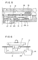
- Fig. 5 shows another modification of the present gear train structure in which the arragement of the balance spring frame 23 is upside down as compared with Fig. 2 so that the bottom portion 23b and the canopy portions 23c of the balance spring frame 23 are respectively arranged in opposition to the second gear train bridge 25 and the base plate 27.
- the balance spring 21 when the braking wheel is raised by holding the upper tenon of the balance spring pinion 17, the balance spring 21 is kept by the bottom portion 23b and therefore there is no danger of the balance spring 21 getting out of the balance spring frame 23 to cause a condition such as shown in Fig. 6 contrary to the case in which the canopy portions 23c of the balance spring frame 23 are on the upper side.
- the location projection e.g., the dowel on the balance spring frame 23 as in the previously mentioned arrangement
- the second indicating wheel or the fourth wheel 9 is rotatably supported by the stepped portion formed on the inner peripheral surface of a second wheel shaft 31 fixedly mounted in the second gear train bridge 25, and the minute indicating wheel or the second wheel 13 is rotatably supported by the stepped portion formed on the outer peripheral surface of the second wheel shaft 31.
- the hour indicating wheel or an hour wheel 33 is rotatably supported by the outer peripheral surface of a center pipe 35 fixedly mounted in the base plate 27.
- each of the hand wheels is supported by the second wheel shaft 31 or the center pipe 35 in a completely independent manner as mentioned previously, there is no possibility of a situation arising in which the second wheel is guided by the fourth wheel or the hour wheel is guided by the second wheel as in the case of the prior art. Therefore, the plane position of each hand wheel is not affected by the other hand wheels and the plane position is accurately determined for each hand wheel independently of the other hand wheels. As a result, the backlash between each of the hand wheels and the corresponding mating gear can be set to a reduced value and the indication deviation of each hand wheel due to the backlash can be reduced to a minimum.
- the space interconnecting the pocket of a battery 37 and the gear train pocket is completely divided into two parts by a wall 27a formed on the base plate 27 and a wall 25a formed on the second gear train bridge 25. Therefore, when replacing the battery 37, dust, nap or the like can be prevented from entering into the gear train.
- a hole 29a is provided to observe the manner in which the teeth 9a of the fourth wheel 9 are controlled by a control lever 39 from the upper surface of the gear train bridge 29 as shown in Fig. 1, by fitting a transparent sheet or the like in the hole 29a, it is possible to prevent the dust, nap or the like deposited on the movement from entering into the gear train section through the hole 29a upon the opening of the back cover.
- the present invention has the effect of preventing the entry into the gear train section of dust, nap or the like tending to cause stopping of the watch and thereby reducing the stopping of the watch and enhancing its reliability.
Landscapes
- Physics & Mathematics (AREA)
- General Physics & Mathematics (AREA)
- Electromechanical Clocks (AREA)
Claims (7)
- Räderwerkkonstruktion für eine elektronische Uhr, wobei die Räderwerkkonstruktion umfasst:- einen Hohlraum für das Räderwerk, welcher ein Räderwerk mit einer Mehrzahl von auf einer Grundplatine (27) drehbar gelagerten Zahnrädern und wenigstens eine Räderwerkbrücke (25) enthält, wobei der Hohlraum für das Räderwerk im Wesentlichen in der Nähe des Zentrums des Uhrwerks angeordnet ist, und- einen Hohlraum für eine Stromquelle, für die Aufnahme einer Stromquelle, die der Versorgung des Räderwerks mit elektrischer Energie dient,dadurch gekennzeichnet, dass die Räderwerkkonstruktion Trennwände (27a, 25a) zur Aufteilung eines Raums umfasst, der den Hohlraum für das Räderwerk und den Hohlraum für die Stromquelle miteinander verbindet, wobei die Grundplatine (27) und die Räderwerkbrücke (25) jeweils eine auf ihnen ausgeformte Trennwand (27a, 25a) aufweisen und so übereinander angeordnet sind, dass der Hohlraum für das Räderwerk und der Hohlraum für die Stromquelle durch die Trennwände voneinander getrennt werden.
- Räderwerkkonstruktion nach Anspruch 1, des Weiteren umfassend:- eine Mehrzahl von Zeiger-Rädern (9; 13; 33), wobei an jedem dieser Räder ein Zeiger angebracht ist;- wenigstens ein Räderwerk für die Übertragung der Rotation einer Antriebseinheit auf die Zeiger-Räder; und- eine Bremsvorrichtung zum Anlegen eines Drehmomentes an das Räderwerk in einer Richtung, welche der Richtung des Räderwerks entgegen gesetzt ist.
- Räderwerkkonstruktion nach Anspruch 2, bei welcher die Bremsvorrichtung umfasst:- ein Zahnrad, das für den Eingriff in das Räderwerk ausgelegt ist;- Eine Feder (21), deren eines Ende an einer Achse des Zahnrades befestigt ist; und- ein Befestigungselement mit einer Umfangswand-Fläche für den Kontakt mit der Seite des freien Endes der Feder.
- Räderwerkkonstruktion nach Anspruch 1, des Weiteren umfassend:- eine Mehrzahl von Zeiger-Rädern (9; 13; 33), wobei an jedem dieser Räder ein Zeiger angebracht ist;- wenigstens ein Räderwerk für die Übertragung der Rotation einer Antriebseinheit auf die Zeiger-Räder; und- eine Bremsvorrichtung zum Anlegen eines Drehmomentes an die Zeiger-Räder in einer Richtung, welche der Rotationsrichtung der Zeiger-Räder entgegen gesetzt ist.
- Räderwerkkonstruktion nach Anspruch 4, bei welcher die Bremsvorrichtung umfasst:- ein Zahnrad, das für den Eingriff in eines der Zeiger-Räder (9, 13, 33) ausgelegt ist;- Eine Feder (21), deren eines Ende an einer Achse des Zahnrades befestigt ist; und- ein Befestigungselement mit einer Umfangswand-Fläche für den Kontakt mit der Seite des freien Endes der Feder.
- Räderwerkkonstruktion nach Anspruch 1, des Weiteren umfassend:- wenigstens drei Achsenteile der Zeiger-Räder (9, 13, 33), welche im Zustand des Eingeführtseins konzentrisch angeordnet sind; und- Eine Mehrzahl von feststehenden Hohlachsen (31, 35), die jeweils zwischen jedem der Achsenteile angeordnet sind, wobei jeder der Achsenteile drehbar gelagert ist, ohne Kontakt mit einem anderen Achsenteil zu haben.
- Eine Uhr, umfassend eine Räderwerkkonstruktion nach Anspruch 1.
Applications Claiming Priority (3)
| Application Number | Priority Date | Filing Date | Title |
|---|---|---|---|
| JP323380/92 | 1992-12-02 | ||
| JP4323380A JP2646946B2 (ja) | 1992-12-02 | 1992-12-02 | 時 計 |
| EP93119148A EP0600399B1 (de) | 1992-12-02 | 1993-11-27 | Räderwerk für elektronische Uhr |
Related Parent Applications (1)
| Application Number | Title | Priority Date | Filing Date |
|---|---|---|---|
| EP93119148A Division EP0600399B1 (de) | 1992-12-02 | 1993-11-27 | Räderwerk für elektronische Uhr |
Publications (3)
| Publication Number | Publication Date |
|---|---|
| EP0838736A2 EP0838736A2 (de) | 1998-04-29 |
| EP0838736A3 EP0838736A3 (de) | 1999-03-17 |
| EP0838736B1 true EP0838736B1 (de) | 2007-12-12 |
Family
ID=18154107
Family Applications (3)
| Application Number | Title | Priority Date | Filing Date |
|---|---|---|---|
| EP97120055A Withdrawn EP0838735A3 (de) | 1992-12-02 | 1993-11-27 | Räderwerk für eine elektronische Uhr |
| EP97120056A Expired - Lifetime EP0838736B1 (de) | 1992-12-02 | 1993-11-27 | Räderwerk für eine elektronische Uhr |
| EP93119148A Expired - Lifetime EP0600399B1 (de) | 1992-12-02 | 1993-11-27 | Räderwerk für elektronische Uhr |
Family Applications Before (1)
| Application Number | Title | Priority Date | Filing Date |
|---|---|---|---|
| EP97120055A Withdrawn EP0838735A3 (de) | 1992-12-02 | 1993-11-27 | Räderwerk für eine elektronische Uhr |
Family Applications After (1)
| Application Number | Title | Priority Date | Filing Date |
|---|---|---|---|
| EP93119148A Expired - Lifetime EP0600399B1 (de) | 1992-12-02 | 1993-11-27 | Räderwerk für elektronische Uhr |
Country Status (4)
| Country | Link |
|---|---|
| US (2) | US5506820A (de) |
| EP (3) | EP0838735A3 (de) |
| JP (1) | JP2646946B2 (de) |
| DE (2) | DE69334193T2 (de) |
Cited By (2)
| Publication number | Priority date | Publication date | Assignee | Title |
|---|---|---|---|---|
| US8740452B2 (en) | 2011-08-17 | 2014-06-03 | Eta Sa Manufacture Horlogère Suisse | Pre-adjustment of timepiece wheel set shake |
| CN106249574A (zh) * | 2015-06-11 | 2016-12-21 | 爱彼钟表业制造有限公司 | 用于钟表的反向器及包括该反向器的自动上链手表 |
Families Citing this family (13)
| Publication number | Priority date | Publication date | Assignee | Title |
|---|---|---|---|---|
| DE69633407T2 (de) * | 1995-11-21 | 2005-03-03 | Seiko Epson Corp. | Elektronische Uhr |
| CN1292318C (zh) * | 2000-11-10 | 2006-12-27 | 西铁城时计株式会社 | 电动钟表的计时机构 |
| US6804172B2 (en) * | 2002-03-07 | 2004-10-12 | Seiko Instruments Inc. | Analog electronic timepiece including plural indicator wheels |
| EP1411400B1 (de) * | 2002-10-16 | 2010-01-06 | ETA SA Manufacture Horlogère Suisse | Befestigungsvorrichtung für ein Koaxialdrehteil in einer Uhr, insbesondere einer Datumanzeigescheibe |
| JP4622274B2 (ja) * | 2004-03-11 | 2011-02-02 | セイコーエプソン株式会社 | ぜんまい残量表示機構および時計 |
| JP4658547B2 (ja) * | 2004-09-13 | 2011-03-23 | シチズンホールディングス株式会社 | クロノグラフ機能付電子時計 |
| JP2007218764A (ja) * | 2006-02-17 | 2007-08-30 | Seiko Instruments Inc | 時計 |
| JP5792400B2 (ja) * | 2012-02-29 | 2015-10-14 | ウーテーアー・エス・アー・マニファクチュール・オロロジェール・スイス | 表盤下の針の取り付け |
| CH710362A1 (fr) * | 2014-11-13 | 2016-05-13 | Société Anonyme De La Mft D'horlogerie Audemars Piguet & Cie | Dispositif de rattrapante à train épicycloïdale pour pièce d'horlogerie. |
| CN106424759B (zh) * | 2016-12-14 | 2019-09-24 | 武汉市联晨精密制造有限公司 | 机械表表芯秒轴加工方法 |
| JP6962101B2 (ja) * | 2017-09-25 | 2021-11-05 | セイコーエプソン株式会社 | 時計用ムーブメントおよび時計 |
| WO2019123821A1 (ja) | 2017-12-20 | 2019-06-27 | シチズン時計株式会社 | 指針の停止位置のばらつき低減機構 |
| JP7467390B2 (ja) * | 2021-06-15 | 2024-04-15 | シチズン時計株式会社 | 指針のふらつき低減構造 |
Family Cites Families (36)
| Publication number | Priority date | Publication date | Assignee | Title |
|---|---|---|---|---|
| DE6941650U (de) * | 1969-10-24 | 1970-01-29 | Kienzle Apparate Gmbh | Anordnung an antriebswerken fuer aufzeichnungstraeger |
| GB1341597A (en) * | 1970-06-09 | 1973-12-25 | Suwa Seikosha Kk | Timepiece mechanism |
| DE7110518U (de) * | 1971-03-19 | 1971-06-09 | Hettich H | Anordnung zur lagerung der sekundenwelle bei wand- und tischuhren |
| JPS5168262A (en) * | 1974-12-10 | 1976-06-12 | Star Mfg Co | Denchidokeino kozo |
| DE2538762C2 (de) * | 1975-09-01 | 1983-12-29 | Kienzle Uhrenfabriken GmbH, 7730 Villingen-Schwenningen | Vorrichtung zum Ausgleich des Zahnspiels bei Uhrwerken |
| JPS52132874A (en) * | 1976-04-30 | 1977-11-07 | Citizen Watch Co Ltd | Electronic timepiece |
| JPS6031275B2 (ja) * | 1977-12-27 | 1985-07-20 | セイコーエプソン株式会社 | 時計の輪列機構 |
| JPS54133878U (de) * | 1978-03-08 | 1979-09-17 | ||
| JPS5540982A (en) * | 1978-09-19 | 1980-03-22 | Citizen Watch Co Ltd | Electronic watch |
| EP0042079A1 (de) * | 1980-06-02 | 1981-12-23 | Manufacture JAEGER-LECOULTRE S.A. | Montageplatte für elektronische Uhren |
| US4496246A (en) * | 1980-10-21 | 1985-01-29 | Kabushiki Kaisha Suwa Seikosha | Timepiece construction |
| JPS5918384A (ja) * | 1982-07-21 | 1984-01-30 | Hitachi Ltd | 直接液−液接触式熱交換器 |
| JPS5918384U (ja) * | 1982-07-28 | 1984-02-03 | 本田技研工業株式会社 | 車輌のカプラ端子取付装置 |
| JPS59104586A (ja) * | 1982-12-07 | 1984-06-16 | Seiko Epson Corp | コンビネ−シヨン時計のモジユ−ル構造 |
| US4726000A (en) * | 1985-04-20 | 1988-02-16 | Diehl Gmbh & Co. | Timepiece |
| CH661403GA3 (de) * | 1985-10-02 | 1987-07-31 | ||
| JPS6346862A (ja) * | 1986-08-14 | 1988-02-27 | Canon Inc | フアクシミリ装置 |
| JPS6372591U (de) * | 1986-10-30 | 1988-05-14 | ||
| JPS63190988A (ja) * | 1987-02-02 | 1988-08-08 | Hitachi Ltd | 流量制御弁 |
| JPS63190988U (de) * | 1987-05-29 | 1988-12-08 | ||
| JP2594103B2 (ja) * | 1987-06-03 | 1997-03-26 | セイコーエプソン株式会社 | 電子時計 |
| JPS6451893U (de) * | 1987-09-28 | 1989-03-30 | ||
| JPH01292286A (ja) * | 1988-05-19 | 1989-11-24 | Seiko Epson Corp | 電子時計 |
| JPH0187288U (de) * | 1987-12-02 | 1989-06-08 | ||
| US4796240A (en) * | 1987-12-14 | 1989-01-03 | Stevens Robert B | Cartridge timepiece |
| JPH01165986A (ja) * | 1987-12-22 | 1989-06-29 | Seiko Epson Corp | 電子時計 |
| JPH0714952Y2 (ja) * | 1987-12-24 | 1995-04-10 | セイコーエプソン株式会社 | 電子時計 |
| US4794576A (en) * | 1988-01-29 | 1988-12-27 | Timex Corporation | Combination electrical contact member and braking member for a timepiece |
| JPH029895A (ja) * | 1988-06-28 | 1990-01-12 | Lion Corp | ヌクレオシド類似化合物及び抗腫瘍剤 |
| JP2503748Y2 (ja) * | 1988-07-05 | 1996-07-03 | シチズン時計株式会社 | 絵板表示水晶腕時計 |
| JPH0233387A (ja) * | 1988-07-21 | 1990-02-02 | Kurosawa Kensetsu Kk | Pcストランドの防錆被覆方法 |
| JPH0233387U (de) * | 1988-08-26 | 1990-03-02 | ||
| JPH02199082A (ja) * | 1989-01-28 | 1990-08-07 | Honda Motor Co Ltd | 部分強化セラミック部材およびその製造方法 |
| JPH02281182A (ja) * | 1989-04-24 | 1990-11-16 | Seiko Epson Corp | アナログ電子時計 |
| JPH04106792A (ja) * | 1990-08-28 | 1992-04-08 | Matsushita Electric Ind Co Ltd | 光連想メモリ装置及びその製造方法 |
| JPH04106792U (ja) * | 1991-02-25 | 1992-09-14 | セイコー電子工業株式会社 | 電子時計 |
-
1992
- 1992-12-02 JP JP4323380A patent/JP2646946B2/ja not_active Expired - Lifetime
-
1993
- 1993-11-24 US US08/157,912 patent/US5506820A/en not_active Expired - Lifetime
- 1993-11-27 DE DE69334193T patent/DE69334193T2/de not_active Expired - Lifetime
- 1993-11-27 EP EP97120055A patent/EP0838735A3/de not_active Withdrawn
- 1993-11-27 EP EP97120056A patent/EP0838736B1/de not_active Expired - Lifetime
- 1993-11-27 EP EP93119148A patent/EP0600399B1/de not_active Expired - Lifetime
- 1993-11-27 DE DE69332014T patent/DE69332014T2/de not_active Expired - Fee Related
-
1995
- 1995-04-12 US US08/420,423 patent/US5617376A/en not_active Expired - Lifetime
Cited By (3)
| Publication number | Priority date | Publication date | Assignee | Title |
|---|---|---|---|---|
| US8740452B2 (en) | 2011-08-17 | 2014-06-03 | Eta Sa Manufacture Horlogère Suisse | Pre-adjustment of timepiece wheel set shake |
| CN106249574A (zh) * | 2015-06-11 | 2016-12-21 | 爱彼钟表业制造有限公司 | 用于钟表的反向器及包括该反向器的自动上链手表 |
| CN106249574B (zh) * | 2015-06-11 | 2020-02-11 | 爱彼钟表业制造有限公司 | 用于钟表的反向器及包括该反向器的自动上链手表 |
Also Published As
| Publication number | Publication date |
|---|---|
| EP0838735A2 (de) | 1998-04-29 |
| EP0600399B1 (de) | 2002-06-12 |
| EP0600399A2 (de) | 1994-06-08 |
| EP0838736A3 (de) | 1999-03-17 |
| JP2646946B2 (ja) | 1997-08-27 |
| DE69334193T2 (de) | 2008-12-04 |
| EP0838736A2 (de) | 1998-04-29 |
| US5506820A (en) | 1996-04-09 |
| DE69332014T2 (de) | 2002-12-19 |
| EP0600399A3 (de) | 1996-03-06 |
| DE69332014D1 (de) | 2002-07-18 |
| US5617376A (en) | 1997-04-01 |
| EP0838735A3 (de) | 1999-03-17 |
| DE69334193D1 (de) | 2008-01-24 |
| JPH06174859A (ja) | 1994-06-24 |
Similar Documents
| Publication | Publication Date | Title |
|---|---|---|
| EP0838736B1 (de) | Räderwerk für eine elektronische Uhr | |
| US4378957A (en) | Reduction gear of electronic wristwatch with stepping motor and sweep second hand | |
| CA2213899C (en) | Calendar watch | |
| US4845693A (en) | Apparatus for correcting a timepiece display | |
| HK1012733A (en) | Gear train structure of an electronic watch | |
| US4636087A (en) | Gear train mechanism stop device of timepiece | |
| JP4723287B2 (ja) | アナログ時計 | |
| JPH0452706Y2 (de) | ||
| JP2617200B2 (ja) | 時計の指針修正機構 | |
| EP1046966A1 (de) | Mechanismus zur gangreserve und dessen anzeigegerät | |
| EP0319304B1 (de) | Uhrwerk | |
| EP1052557B1 (de) | Zeitmessgerät | |
| JP3642323B2 (ja) | 時計 | |
| JP2537618B2 (ja) | 電子時計 | |
| JPH045797Y2 (de) | ||
| JPS6033415Y2 (ja) | 目覚し時計等に於ける目安修正機構 | |
| JPH06105308B2 (ja) | 時計の指針修正装置 | |
| JPS5877682A (ja) | 時計の輪列機構 | |
| JPH0752628Y2 (ja) | 時計の輪列回転規制装置 | |
| JPH0616333Y2 (ja) | カレンダー修正機構付時計 | |
| JPS598225Y2 (ja) | 時計の暦修正装置 | |
| JP2002341055A (ja) | 回転表示板付き時計の構造 | |
| JPS637906Y2 (de) | ||
| JPS636708Y2 (de) | ||
| JPS6020063Y2 (ja) | 時計の停止装置 |
Legal Events
| Date | Code | Title | Description |
|---|---|---|---|
| PUAI | Public reference made under article 153(3) epc to a published international application that has entered the european phase |
Free format text: ORIGINAL CODE: 0009012 |
|
| AC | Divisional application: reference to earlier application |
Ref document number: 600399 Country of ref document: EP |
|
| AK | Designated contracting states |
Kind code of ref document: A2 Designated state(s): CH DE FR GB LI |
|
| PUAL | Search report despatched |
Free format text: ORIGINAL CODE: 0009013 |
|
| AK | Designated contracting states |
Kind code of ref document: A3 Designated state(s): CH DE FR GB LI |
|
| 17P | Request for examination filed |
Effective date: 19990917 |
|
| 17Q | First examination report despatched |
Effective date: 20060803 |
|
| GRAP | Despatch of communication of intention to grant a patent |
Free format text: ORIGINAL CODE: EPIDOSNIGR1 |
|
| GRAS | Grant fee paid |
Free format text: ORIGINAL CODE: EPIDOSNIGR3 |
|
| GRAA | (expected) grant |
Free format text: ORIGINAL CODE: 0009210 |
|
| AC | Divisional application: reference to earlier application |
Ref document number: 0600399 Country of ref document: EP Kind code of ref document: P |
|
| AK | Designated contracting states |
Kind code of ref document: B1 Designated state(s): CH DE FR GB LI |
|
| REG | Reference to a national code |
Ref country code: GB Ref legal event code: FG4D |
|
| REG | Reference to a national code |
Ref country code: CH Ref legal event code: EP |
|
| REF | Corresponds to: |
Ref document number: 69334193 Country of ref document: DE Date of ref document: 20080124 Kind code of ref document: P |
|
| REG | Reference to a national code |
Ref country code: CH Ref legal event code: NV Representative=s name: KIRKER & CIE S.A. |
|
| ET | Fr: translation filed | ||
| PLBE | No opposition filed within time limit |
Free format text: ORIGINAL CODE: 0009261 |
|
| 26N | No opposition filed |
Effective date: 20080915 |
|
| PGFP | Annual fee paid to national office [announced via postgrant information from national office to epo] |
Ref country code: DE Payment date: 20121121 Year of fee payment: 20 Ref country code: CH Payment date: 20121113 Year of fee payment: 20 Ref country code: FR Payment date: 20121130 Year of fee payment: 20 |
|
| PGFP | Annual fee paid to national office [announced via postgrant information from national office to epo] |
Ref country code: GB Payment date: 20121121 Year of fee payment: 20 |
|
| REG | Reference to a national code |
Ref country code: DE Ref legal event code: R071 Ref document number: 69334193 Country of ref document: DE |
|
| REG | Reference to a national code |
Ref country code: CH Ref legal event code: PL |
|
| REG | Reference to a national code |
Ref country code: GB Ref legal event code: PE20 Expiry date: 20131126 |
|
| PG25 | Lapsed in a contracting state [announced via postgrant information from national office to epo] |
Ref country code: DE Free format text: LAPSE BECAUSE OF EXPIRATION OF PROTECTION Effective date: 20131128 Ref country code: GB Free format text: LAPSE BECAUSE OF EXPIRATION OF PROTECTION Effective date: 20131126 |