EP0841296A1 - Containerkrahn - Google Patents
Containerkrahn Download PDFInfo
- Publication number
- EP0841296A1 EP0841296A1 EP97308691A EP97308691A EP0841296A1 EP 0841296 A1 EP0841296 A1 EP 0841296A1 EP 97308691 A EP97308691 A EP 97308691A EP 97308691 A EP97308691 A EP 97308691A EP 0841296 A1 EP0841296 A1 EP 0841296A1
- Authority
- EP
- European Patent Office
- Prior art keywords
- spreader
- head block
- trolley
- oscillation
- container
- Prior art date
- Legal status (The legal status is an assumption and is not a legal conclusion. Google has not performed a legal analysis and makes no representation as to the accuracy of the status listed.)
- Withdrawn
Links
Images




Classifications
-
- B—PERFORMING OPERATIONS; TRANSPORTING
- B66—HOISTING; LIFTING; HAULING
- B66C—CRANES; LOAD-ENGAGING ELEMENTS OR DEVICES FOR CRANES, CAPSTANS, WINCHES, OR TACKLES
- B66C13/00—Other constructional features or details
- B66C13/18—Control systems or devices
- B66C13/40—Applications of devices for transmitting control pulses; Applications of remote control devices
- B66C13/42—Hydraulic transmitters
-
- B—PERFORMING OPERATIONS; TRANSPORTING
- B66—HOISTING; LIFTING; HAULING
- B66C—CRANES; LOAD-ENGAGING ELEMENTS OR DEVICES FOR CRANES, CAPSTANS, WINCHES, OR TACKLES
- B66C13/00—Other constructional features or details
- B66C13/04—Auxiliary devices for controlling movements of suspended loads, or preventing cable slack
- B66C13/08—Auxiliary devices for controlling movements of suspended loads, or preventing cable slack for depositing loads in desired attitudes or positions
-
- B—PERFORMING OPERATIONS; TRANSPORTING
- B66—HOISTING; LIFTING; HAULING
- B66C—CRANES; LOAD-ENGAGING ELEMENTS OR DEVICES FOR CRANES, CAPSTANS, WINCHES, OR TACKLES
- B66C1/00—Load-engaging elements or devices attached to lifting or lowering gear of cranes or adapted for connection therewith for transmitting lifting forces to articles or groups of articles
- B66C1/10—Load-engaging elements or devices attached to lifting or lowering gear of cranes or adapted for connection therewith for transmitting lifting forces to articles or groups of articles by mechanical means
- B66C1/101—Load-engaging elements or devices attached to lifting or lowering gear of cranes or adapted for connection therewith for transmitting lifting forces to articles or groups of articles by mechanical means for containers
-
- B—PERFORMING OPERATIONS; TRANSPORTING
- B66—HOISTING; LIFTING; HAULING
- B66C—CRANES; LOAD-ENGAGING ELEMENTS OR DEVICES FOR CRANES, CAPSTANS, WINCHES, OR TACKLES
- B66C13/00—Other constructional features or details
- B66C13/04—Auxiliary devices for controlling movements of suspended loads, or preventing cable slack
- B66C13/06—Auxiliary devices for controlling movements of suspended loads, or preventing cable slack for minimising or preventing longitudinal or transverse swinging of loads
-
- B—PERFORMING OPERATIONS; TRANSPORTING
- B66—HOISTING; LIFTING; HAULING
- B66C—CRANES; LOAD-ENGAGING ELEMENTS OR DEVICES FOR CRANES, CAPSTANS, WINCHES, OR TACKLES
- B66C19/00—Cranes comprising trolleys or crabs running on fixed or movable bridges or gantries
- B66C19/007—Cranes comprising trolleys or crabs running on fixed or movable bridges or gantries for containers
-
- B—PERFORMING OPERATIONS; TRANSPORTING
- B66—HOISTING; LIFTING; HAULING
- B66C—CRANES; LOAD-ENGAGING ELEMENTS OR DEVICES FOR CRANES, CAPSTANS, WINCHES, OR TACKLES
- B66C2700/00—Cranes
- B66C2700/01—General aspects of mobile cranes, overhead travelling cranes, gantry cranes, loading bridges, cranes for building ships on slipways, cranes for foundries or cranes for public works
- B66C2700/012—Trolleys or runways
-
- B—PERFORMING OPERATIONS; TRANSPORTING
- B66—HOISTING; LIFTING; HAULING
- B66C—CRANES; LOAD-ENGAGING ELEMENTS OR DEVICES FOR CRANES, CAPSTANS, WINCHES, OR TACKLES
- B66C2700/00—Cranes
- B66C2700/08—Electrical assemblies or electrical control devices for cranes, winches, capstans or electrical hoists
- B66C2700/085—Control actuators
Definitions
- the present invention relates to a container crane of the type including a trolley adapted to be moved in a traverse direction along traverse rails, a head block hoistably suspended from the trolley and a spreader which is connected to the head block and is adapted to grip a container.
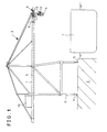
- the illustrated known container crane 3 is intended for loading and unloading containers 4 onto and from a container ship 1 moored at a quay 2.
- the crane 3 comprises upstanding legs 6 adapted to run along rails 5 on the quay 2, girders 7 on top of the legs 6 and extending substantially horizontally towards the sea.
- traverse rails 8 extending along the girders 7 and a trolley 9 adapted to be moved in a traverse direction along the rails 8.
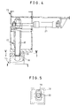
- the trolley 9 comprises a trolley body 11 with traverse wheels 12 for rolling on the rails 8. Tied to the trolley body 11 are opposite ends of a traverse rope 13 which is wound around a traverse drum (not shown) in a machine room 10 (see Figure 1) and which extends under tension longitudinally of the girders 7. Rotation of the traverse drum in the normal or reverse direction causes the trolley 9 to be moved in the traverse direction.
- the trolley 9 carries a head block 15 which is suspended from the trolley 9 by winding ropes 14 which in turn are wound around a hoist drum (not shown) in the machine room 10 and which extend under tension longitudinally of the girders 7. Rotation of the hoist drum in the normal or reverse direction causes the head block 15 to be hoisted up or down.
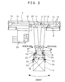
- a spreader 16 Detachably interlocked with the head block 15 by means of twist locks 17 is a spreader 16 which grips a container 4.
- each of the twist locks 17 comprises a lock pin 20 which is inserted into a corresponding suspender 18 of the spreader 16 through a slot 19 in the suspender 18 and is turned by actuation of a hydraulic cylinder 21 to interlock the head block 15 with the spreader 16.
- the spreader 16 comprises a spreader body 16a with extension frames 22, each of which is mounted on the body 1 6a to be slidable by a drive (not shown) perpendicularly of the traverse direction of the trolley 9.
- Each frame 22 is provided at its outer corners with twist locks 23 for gripping the container 4 and with guide arms 24 for moving the twist locks 23 into position for engagement with the container 4.
- the spreader 16 can grip containers 4 of different lengths since the difference in length of the containers 4 can be compensated for by sliding displacement of the frames 22.
- the twist locks 23 can interlock the spreader 14 with a container 4 by inserting a lock pin of a twist lock 23 into the container 4 through a slot therein and turning it by actuation of a hydraulic cylinder.
- the guide arms 24 can be swung from an upper, turned-over open position into position for engagement with a corner of the container 4 by actuation of a hydraulic motor 25. Therefore, the spreader 16 can be correctly positioned with respect to the container 4 and the twist locks 23 can be positively engaged with the container 4 even if there may be some positional inaccuracy in lowering the spreader 16 interlocked with the head block 15 onto the container 4.
- the container 4 generally has a predetermined destination on the container ship 1. Therefore, in accordance with the coordinates of the destination of the container 4, the trolley 9 may be automatically moved in the traverse direction and only hoisting-up and -down of the spreader 16 need be carried out manually by an operator in an operation room 26.
- the spreader 16 gripping the container tends to swing or oscillate due to inertia when accelerated or decelerated or as a result of any wind that may be blowing, resulting in difficulties in the loading and unloading operation.
- the sheaves 27 on the trolley 9. which support the hoist ropes 14 for the head block 15 and spreader 16, are separated from each other by drive means (not shown) so that the hoist ropes 14 for the head block 15 and spreader 16 are in the shape of the letter V in order to suppress swinging or oscillation of the head block 15 and spreader 16.
- Such a mechanical swing- or oscillation-suppressing mechanism is effective only to suppress sway (pendulum-like swinging or oscillation; see Figure 2) and is substantially ineffective to suppress rocking (rotational swinging or oscillation around an axis below the suspended position; see Figure 2) or skew (swinging or oscillation in a horizontal plane; see Figure 6).
- a container crane of the type referred to above is characterised by two or more oscillation sensors arranged on the head block or spreader and adapted to sense oscillation of the head block or spreader in the traverse direction of the trolley, the sensors being arranged symmetrically with respect to the transverse centre line of the head block or spreader, respectively, and two or more damping means arranged on the head block or spreader, each including a mass movable in the traverse direction of the trolley and an actuator arranged to move the movable mass in response to oscillation of the head block or spreader sensed by the sensors in a direction to counteract the oscillation, the damping means being arranged symmetrically with respect to the transverse centre line of the head block or spreader, respectively.
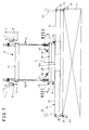
- FIGs 7 and 8 illustrate an embodiment of the present invention in which the same components as in Figures 11 to 6 are referred to by the same reference numerals and whose basic arrangement is the same as that in the known system shown in Figures 1 to 6.
- vibration or oscillation sensors 28 such as acceleration sensors or speed sensors, for sensing any oscillation of the head block 15 in the traverse direction of the trolley 9 are arranged symmetrically with respect to the transverse centre line L of the head block 15.
- Active damping means 31 each having a mass 29 movable in the traverse direction of the trolley 9 and an actuator 30 for driving the movable mass 29 in the direction to counteract the oscillation of the head block 15 sensed by the vibration sensor 28 are also arranged symmetrically with respect to the transverse centre line L of the head block 15.
- Each of the damping means 31 includes a nut member 33 screwed onto a screw shaft 32 extending in the traverse direction of the trolley 9 and the movable mass 29 is integrally mounted on the nut member 3. Rotation of the screw shaft 32 by the actuator 30 forcibly causes the movable mass 29 to be moved in the same cycle and with the same wavelength as the oscillation of the head block 15 but with a phase difference of 90° therefrom.
- each of the oscillation or vibration sensors 28 which are arranged symmetrically with respect to the transverse centre line L of the head block 15.
- the movable mass 29 of each of the damping means 31 is driven independently by the associated actuator 30 so as to counteract or damp the oscillation.
- both the vibration sensors 28 and the damping means 31 are arranged symmetrically with respect to the transverse line L of the head lock 15 and can cope with and suppress any type of oscillation such as sway, rocking or skew of the head block 15 and thus of the spreader 16 and any container carried by it. The loading and unloading operations can thus be performed efficiently.
- FIGS 9 and 10 illustrate a further embodiment of the present invention in which the same components as in Figures 7 and 8 are referred to by the same reference numerals.
- Oscillation sensors 28, such as acceleration sensors and speed sensors, for sensing oscillation of the spreader 16 in the traverse direction of the trolley 9 are arranged on the spreader 16, symmetrically with respect to the transverse centre line L of the spreader 16.
- two active damping means 31, each having a mass 29 movable in the traverse direction of the trolley 9, and an actuator 30 for driving the movable mass 29 in a direction to counteract the oscillation of the spreader 16 detected by the vibration sensors 28 are arranged on the spreader 16 symmetrically with respect to its transverse centre line L.
- damping means are the same as those described above in conjunction with Figures 7 and 8.
- the same advantages are also obtained in that sway, rocking or skew of the spreader 16 may again be suppressed, thereby permitting loading and unloading operations to be performed efficiently.
Landscapes
- Engineering & Computer Science (AREA)
- Mechanical Engineering (AREA)
- Automation & Control Theory (AREA)
- Control And Safety Of Cranes (AREA)
- Load-Engaging Elements For Cranes (AREA)
Applications Claiming Priority (4)
| Application Number | Priority Date | Filing Date | Title |
|---|---|---|---|
| JP294912/96 | 1996-11-07 | ||
| JP29491296A JPH10139366A (ja) | 1996-11-07 | 1996-11-07 | コンテナクレーンのスプレッダ |
| JP30295396A JPH10139361A (ja) | 1996-11-14 | 1996-11-14 | コンテナクレーンのヘッドブロック |
| JP302953/96 | 1996-11-14 |
Publications (1)
| Publication Number | Publication Date |
|---|---|
| EP0841296A1 true EP0841296A1 (de) | 1998-05-13 |
Family
ID=26560039
Family Applications (1)
| Application Number | Title | Priority Date | Filing Date |
|---|---|---|---|
| EP97308691A Withdrawn EP0841296A1 (de) | 1996-11-07 | 1997-10-30 | Containerkrahn |
Country Status (5)
| Country | Link |
|---|---|
| EP (1) | EP0841296A1 (de) |
| KR (1) | KR19980041984A (de) |
| CN (1) | CN1184074A (de) |
| AU (1) | AU4275497A (de) |
| CA (1) | CA2219433A1 (de) |
Cited By (10)
| Publication number | Priority date | Publication date | Assignee | Title |
|---|---|---|---|---|
| DE19918449C2 (de) * | 1999-04-23 | 2001-09-13 | Noell Stahl Und Maschb Gmbh | Lasthebesystem zur Feinpositionierung und aktiven Schwingungsdämpfung |
| SG91286A1 (en) * | 1999-08-12 | 2002-09-17 | Mitsubishi Heavy Ind Ltd | Crane apparatus |
| WO2006024701A1 (en) * | 2004-09-01 | 2006-03-09 | Kalmar Industries Oy Ab | Stopping the skew motion of a container |
| US7121012B2 (en) | 1999-12-14 | 2006-10-17 | Voecks Larry A | Apparatus and method for measuring and controlling pendulum motion |
| US7261351B1 (en) * | 2000-04-24 | 2007-08-28 | Nsl Engineering Pte Ltd | Spreader including a detection system |
| US7845087B2 (en) | 1999-12-14 | 2010-12-07 | Voecks Larry A | Apparatus and method for measuring and controlling pendulum motion |
| CN101590986B (zh) * | 2009-04-30 | 2011-08-03 | 大连华锐股份有限公司 | 起重机用起升机构实时监控方法 |
| EP2574819A1 (de) | 2011-09-30 | 2013-04-03 | Siemens Aktiengesellschaft | Geschwindigkeitsproportionale aktive Schwingungsdämpfung |
| EP2902356A1 (de) * | 2014-01-29 | 2015-08-05 | Siemens Aktiengesellschaft | Kran mit aktiver Dämpfung von Pendelbewegungen der Last |
| CN107285198A (zh) * | 2017-08-01 | 2017-10-24 | 润邦卡哥特科工业有限公司 | 一种起重机吊具减摇系统及其操作方法 |
Families Citing this family (7)
| Publication number | Priority date | Publication date | Assignee | Title |
|---|---|---|---|---|
| DE20216321U1 (de) * | 2002-05-13 | 2003-02-20 | Noell Crane Systems GmbH, 97080 Würzburg | Katze für einen Kran |
| CN106477419A (zh) * | 2015-08-27 | 2017-03-08 | 富士电梯(合肥)有限公司 | 一种电梯启停稳定装置及其控制方法 |
| CN106477423A (zh) * | 2015-08-27 | 2017-03-08 | 富士电梯(合肥)有限公司 | 一种电梯防抖动装置及其防抖动方法 |
| KR101702779B1 (ko) * | 2015-10-29 | 2017-02-03 | 세메스 주식회사 | 반송 대차의 핸드 유닛 |
| KR20220100670A (ko) * | 2019-11-20 | 2022-07-15 | 무라다기카이가부시끼가이샤 | 천장 반송차 |
| CN111717802A (zh) * | 2020-06-22 | 2020-09-29 | 北京中铁装饰工程有限公司 | 一种基于5g技术的超高层幕墙吊装系统 |
| CN111762675B (zh) * | 2020-08-04 | 2024-11-26 | 连云港澳达康国际货运代理有限公司 | 一种用于集装箱装卸桥的双集装箱液压翻转吊具 |
Citations (5)
| Publication number | Priority date | Publication date | Assignee | Title |
|---|---|---|---|---|
| US1694084A (en) * | 1926-05-25 | 1928-12-04 | Halver R Straight | Crane |
| US3210114A (en) * | 1963-11-21 | 1965-10-05 | Lawton Lawrence | Apparatus for orienting a suspended load |
| DE2356504A1 (de) * | 1973-11-13 | 1975-05-15 | Krupp Gmbh | Lastaufnahmemittel eines hebezeuges, insbesondere eines container-kranes |
| US5186342A (en) * | 1990-11-07 | 1993-02-16 | Paceco Corp. | Integrated passive sway arrest system for cargo container handling cranes |
| GB2300177A (en) * | 1995-04-24 | 1996-10-30 | Mitsubishi Heavy Ind Ltd | Preventing Load Vibration |
-
1997
- 1997-10-22 AU AU42754/97A patent/AU4275497A/en not_active Abandoned
- 1997-10-24 CA CA002219433A patent/CA2219433A1/en not_active Abandoned
- 1997-10-30 EP EP97308691A patent/EP0841296A1/de not_active Withdrawn
- 1997-10-31 KR KR1019970056775A patent/KR19980041984A/ko not_active Withdrawn
- 1997-11-06 CN CN97122265A patent/CN1184074A/zh active Pending
Patent Citations (5)
| Publication number | Priority date | Publication date | Assignee | Title |
|---|---|---|---|---|
| US1694084A (en) * | 1926-05-25 | 1928-12-04 | Halver R Straight | Crane |
| US3210114A (en) * | 1963-11-21 | 1965-10-05 | Lawton Lawrence | Apparatus for orienting a suspended load |
| DE2356504A1 (de) * | 1973-11-13 | 1975-05-15 | Krupp Gmbh | Lastaufnahmemittel eines hebezeuges, insbesondere eines container-kranes |
| US5186342A (en) * | 1990-11-07 | 1993-02-16 | Paceco Corp. | Integrated passive sway arrest system for cargo container handling cranes |
| GB2300177A (en) * | 1995-04-24 | 1996-10-30 | Mitsubishi Heavy Ind Ltd | Preventing Load Vibration |
Cited By (12)
| Publication number | Priority date | Publication date | Assignee | Title |
|---|---|---|---|---|
| DE19918449C2 (de) * | 1999-04-23 | 2001-09-13 | Noell Stahl Und Maschb Gmbh | Lasthebesystem zur Feinpositionierung und aktiven Schwingungsdämpfung |
| SG91286A1 (en) * | 1999-08-12 | 2002-09-17 | Mitsubishi Heavy Ind Ltd | Crane apparatus |
| US7121012B2 (en) | 1999-12-14 | 2006-10-17 | Voecks Larry A | Apparatus and method for measuring and controlling pendulum motion |
| US7395605B2 (en) | 1999-12-14 | 2008-07-08 | Voecks Larry A | Apparatus and method for measuring and controlling pendulum motion |
| US7845087B2 (en) | 1999-12-14 | 2010-12-07 | Voecks Larry A | Apparatus and method for measuring and controlling pendulum motion |
| US7261351B1 (en) * | 2000-04-24 | 2007-08-28 | Nsl Engineering Pte Ltd | Spreader including a detection system |
| WO2006024701A1 (en) * | 2004-09-01 | 2006-03-09 | Kalmar Industries Oy Ab | Stopping the skew motion of a container |
| CN101590986B (zh) * | 2009-04-30 | 2011-08-03 | 大连华锐股份有限公司 | 起重机用起升机构实时监控方法 |
| EP2574819A1 (de) | 2011-09-30 | 2013-04-03 | Siemens Aktiengesellschaft | Geschwindigkeitsproportionale aktive Schwingungsdämpfung |
| US9316283B2 (en) | 2011-09-30 | 2016-04-19 | Siemens Aktiengesellschaft | Velocity-proportional active vibration damping |
| EP2902356A1 (de) * | 2014-01-29 | 2015-08-05 | Siemens Aktiengesellschaft | Kran mit aktiver Dämpfung von Pendelbewegungen der Last |
| CN107285198A (zh) * | 2017-08-01 | 2017-10-24 | 润邦卡哥特科工业有限公司 | 一种起重机吊具减摇系统及其操作方法 |
Also Published As
| Publication number | Publication date |
|---|---|
| KR19980041984A (ko) | 1998-08-17 |
| CA2219433A1 (en) | 1998-05-07 |
| AU4275497A (en) | 1998-05-14 |
| CN1184074A (zh) | 1998-06-10 |
Similar Documents
| Publication | Publication Date | Title |
|---|---|---|
| EP0841296A1 (de) | Containerkrahn | |
| JPH09142774A (ja) | コンテナクレーンの吊荷の振れ止め方法およびその装置 | |
| KR20120049874A (ko) | 탠덤 리프트 카고 컨테이너 처리용 와이어 로프 리빙 시스템 | |
| JP2572724B2 (ja) | コンテナクレーンの荷振れ時の旋回動作防止装置 | |
| KR20190041015A (ko) | 크레인 장비, 특히 컨테이너 크레인을 위한 동작 방법 | |
| WO2006024701A1 (en) | Stopping the skew motion of a container | |
| JP2014189389A (ja) | クレーンとその制御方法 | |
| JP4481031B2 (ja) | トロリクレーンとその振れ止め方法 | |
| JP2017178580A (ja) | 岸壁クレーン | |
| CN207346993U (zh) | 装船智能化钢卷夹具 | |
| JP2000272871A (ja) | コンテナクレーンのスプレッダ | |
| JP2000272884A (ja) | コンテナクレーン | |
| JP3035769B2 (ja) | 表面処理装置 | |
| JPH11314881A (ja) | 荷役装置の振れ止め装置 | |
| JPH10139366A (ja) | コンテナクレーンのスプレッダ | |
| JPH01267297A (ja) | 吊荷の振れ止め制御方法及び振れ止め制御における位置決め制御方法 | |
| CN223534704U (zh) | 一种水泥搬运的桥式卸船装置 | |
| JPH1017268A (ja) | クレーン吊荷のスキュー振れ止め方法および装置 | |
| JP2955493B2 (ja) | クレーンの吊荷の旋回姿勢制御方法 | |
| JPH10139361A (ja) | コンテナクレーンのヘッドブロック | |
| KR100255882B1 (ko) | 유압실린더 제어를 이용한 스웨이 제동용 쉬브 작동 시스템 | |
| JP3321988B2 (ja) | ケーブルクレーンの荷振れ止め方法及びその装置 | |
| JP4462733B2 (ja) | 吊荷の制振装置及び制振方法 | |
| JP2002193582A (ja) | コンテナクレーンの振止装置 | |
| KR20000066572A (ko) | 크레인 자동 흔들림 방지 시스템 |
Legal Events
| Date | Code | Title | Description |
|---|---|---|---|
| PUAI | Public reference made under article 153(3) epc to a published international application that has entered the european phase |
Free format text: ORIGINAL CODE: 0009012 |
|
| AK | Designated contracting states |
Kind code of ref document: A1 Designated state(s): AT BE CH DE DK ES FI FR GB GR IE IT LI LU MC NL PT SE |
|
| AX | Request for extension of the european patent |
Free format text: AL;LT;LV;RO;SI |
|
| AKX | Designation fees paid | ||
| RBV | Designated contracting states (corrected) | ||
| STAA | Information on the status of an ep patent application or granted ep patent |
Free format text: STATUS: THE APPLICATION IS DEEMED TO BE WITHDRAWN |
|
| 18D | Application deemed to be withdrawn |
Effective date: 19981114 |