EP0841504A2 - Dispositif hydraulique de commande d'une transmission à variation continue - Google Patents
Dispositif hydraulique de commande d'une transmission à variation continue Download PDFInfo
- Publication number
- EP0841504A2 EP0841504A2 EP97308037A EP97308037A EP0841504A2 EP 0841504 A2 EP0841504 A2 EP 0841504A2 EP 97308037 A EP97308037 A EP 97308037A EP 97308037 A EP97308037 A EP 97308037A EP 0841504 A2 EP0841504 A2 EP 0841504A2
- Authority
- EP
- European Patent Office
- Prior art keywords
- pressure
- control
- pulley
- sol
- valve
- Prior art date
- Legal status (The legal status is an assumption and is not a legal conclusion. Google has not performed a legal analysis and makes no representation as to the accuracy of the status listed.)
- Granted
Links
- 230000005540 biological transmission Effects 0.000 title claims abstract description 36
- 230000008859 change Effects 0.000 claims abstract description 48
- 230000001105 regulatory effect Effects 0.000 claims abstract description 13
- 230000001965 increasing effect Effects 0.000 abstract description 11
- 239000000969 carrier Substances 0.000 description 5
- 238000010276 construction Methods 0.000 description 5
- 238000010586 diagram Methods 0.000 description 5
- 230000007423 decrease Effects 0.000 description 3
- 230000001276 controlling effect Effects 0.000 description 2
- 239000000446 fuel Substances 0.000 description 2
- 230000007246 mechanism Effects 0.000 description 2
- 230000008901 benefit Effects 0.000 description 1
- 230000008878 coupling Effects 0.000 description 1
- 238000010168 coupling process Methods 0.000 description 1
- 238000005859 coupling reaction Methods 0.000 description 1
- 230000003247 decreasing effect Effects 0.000 description 1
- 230000005611 electricity Effects 0.000 description 1
- 230000002708 enhancing effect Effects 0.000 description 1
- 230000004048 modification Effects 0.000 description 1
- 238000012986 modification Methods 0.000 description 1
- 230000009467 reduction Effects 0.000 description 1
- 230000004044 response Effects 0.000 description 1
Images



Classifications
-
- F—MECHANICAL ENGINEERING; LIGHTING; HEATING; WEAPONS; BLASTING
- F16—ENGINEERING ELEMENTS AND UNITS; GENERAL MEASURES FOR PRODUCING AND MAINTAINING EFFECTIVE FUNCTIONING OF MACHINES OR INSTALLATIONS; THERMAL INSULATION IN GENERAL
- F16H—GEARING
- F16H61/00—Control functions within control units of change-speed- or reversing-gearings for conveying rotary motion ; Control of exclusively fluid gearing, friction gearing, gearings with endless flexible members or other particular types of gearing
- F16H61/66—Control functions within control units of change-speed- or reversing-gearings for conveying rotary motion ; Control of exclusively fluid gearing, friction gearing, gearings with endless flexible members or other particular types of gearing specially adapted for continuously variable gearings
- F16H61/662—Control functions within control units of change-speed- or reversing-gearings for conveying rotary motion ; Control of exclusively fluid gearing, friction gearing, gearings with endless flexible members or other particular types of gearing specially adapted for continuously variable gearings with endless flexible members
- F16H61/66254—Control functions within control units of change-speed- or reversing-gearings for conveying rotary motion ; Control of exclusively fluid gearing, friction gearing, gearings with endless flexible members or other particular types of gearing specially adapted for continuously variable gearings with endless flexible members controlling of shifting being influenced by a signal derived from the engine and the main coupling
- F16H61/66259—Control functions within control units of change-speed- or reversing-gearings for conveying rotary motion ; Control of exclusively fluid gearing, friction gearing, gearings with endless flexible members or other particular types of gearing specially adapted for continuously variable gearings with endless flexible members controlling of shifting being influenced by a signal derived from the engine and the main coupling using electrical or electronical sensing or control means
-
- F—MECHANICAL ENGINEERING; LIGHTING; HEATING; WEAPONS; BLASTING
- F16—ENGINEERING ELEMENTS AND UNITS; GENERAL MEASURES FOR PRODUCING AND MAINTAINING EFFECTIVE FUNCTIONING OF MACHINES OR INSTALLATIONS; THERMAL INSULATION IN GENERAL
- F16H—GEARING
- F16H61/00—Control functions within control units of change-speed- or reversing-gearings for conveying rotary motion ; Control of exclusively fluid gearing, friction gearing, gearings with endless flexible members or other particular types of gearing
- F16H61/02—Control functions within control units of change-speed- or reversing-gearings for conveying rotary motion ; Control of exclusively fluid gearing, friction gearing, gearings with endless flexible members or other particular types of gearing characterised by the signals used
- F16H61/0202—Control functions within control units of change-speed- or reversing-gearings for conveying rotary motion ; Control of exclusively fluid gearing, friction gearing, gearings with endless flexible members or other particular types of gearing characterised by the signals used the signals being electric
- F16H61/0251—Elements specially adapted for electric control units, e.g. valves for converting electrical signals to fluid signals
- F16H2061/0253—Details of electro hydraulic valves, e.g. lands, ports, spools or springs
-
- F—MECHANICAL ENGINEERING; LIGHTING; HEATING; WEAPONS; BLASTING
- F16—ENGINEERING ELEMENTS AND UNITS; GENERAL MEASURES FOR PRODUCING AND MAINTAINING EFFECTIVE FUNCTIONING OF MACHINES OR INSTALLATIONS; THERMAL INSULATION IN GENERAL
- F16H—GEARING
- F16H61/00—Control functions within control units of change-speed- or reversing-gearings for conveying rotary motion ; Control of exclusively fluid gearing, friction gearing, gearings with endless flexible members or other particular types of gearing
- F16H61/66—Control functions within control units of change-speed- or reversing-gearings for conveying rotary motion ; Control of exclusively fluid gearing, friction gearing, gearings with endless flexible members or other particular types of gearing specially adapted for continuously variable gearings
- F16H61/662—Control functions within control units of change-speed- or reversing-gearings for conveying rotary motion ; Control of exclusively fluid gearing, friction gearing, gearings with endless flexible members or other particular types of gearing specially adapted for continuously variable gearings with endless flexible members
- F16H61/66272—Control functions within control units of change-speed- or reversing-gearings for conveying rotary motion ; Control of exclusively fluid gearing, friction gearing, gearings with endless flexible members or other particular types of gearing specially adapted for continuously variable gearings with endless flexible members characterised by means for controlling the torque transmitting capability of the gearing
Definitions
- the present invention relates to a continuously variable transmission having an endless belt reeved around a drive pulley and a driven pulley and more particularly to a hydraulic control apparatus for hydraulically controlling the gear ratio of the transmission.
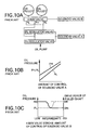
- FIG 10A is a diagrammatic illustration of a conventional hydraulic control apparatus for belt type continuously variable transmissions.
- the delivery pressure of an oil pump is regulated by a PH regulator valve and a PL regulator valve.
- a high or PH pressure output and a low or PL pressure output from these regulator valves are switched by a four-way valve to supply the PH pressure to a drive pulley and the PL pressure to a driven pulley to change the gear ratio to a high-speed or overdrive (OD) speed gear.
- the PL pressure is supplied to the drive pulley and the PH pressure is supplied to the driven pulley to change the gear ratio to a low (LOW) speed gear.
- the PH regulator valve and the PL regulator valve are controlled by a common solenoid valve A, and the four-way valve is controlled by a solenoid valve B.
- This conventional hydraulic control apparatus has a drawback that, as shown in Figure 10B, once the amount of control of the solenoid valve A is determined, the pressure difference between the PH pressure and the PL pressure is also determined, making it impossible to arbitrarily control the speed change time of the belt type continuously variable transmission. Further, with the four-way valve used in the above conventional hydraulic control apparatus, the dimension of overlap between a spool groove and a valve body port cannot be controlled easily. Still another problem is that, as shown in Figure 10C, because of a sharp change in the output hydraulic pressure with respect to the stroke of the spool of the four-way valve, it is difficult to make a fine speed change control.
- the present invention has been accomplished under these circumstances and its objective is to provide a hydraulic control apparatus for a continuously variable transmission that can output a stable pulley pressure and control the speed change time by the use of solenoid valves, and which does not require a four-way valve.
- the apparatus comprises: a regulator valve producing a line pressure; a first solenoid valve producing a first control pressure; a first control valve to regulate the line pressure according to the first control pressure to produce a drive pulley pressure; a second solenoid valve to produce a second control pressure; a second control valve to regulate the line pressure according to the second control pressure to produce a driven pulley pressure; and a control means to fix an electric current value applied to one of the first and second solenoid valves and change an electric current value applied to the other solenoid valve.
- the line pressures are not regulated by the first and second solenoid valves but are output as a drive pulley pressure and a driven pulley pressure, thus holding the gear ratio.
- the first control pressure output from the first solenoid valve changes, causing the drive pulley pressure produced by the first control valve to change, with the result that the gear ratio is changed by the pressure difference between the pulley pressures.
- the speed change time can be controlled. Further, because the drive pulley pressure and the driven pulley pressure are controlled individually by the first control valve and the second control valve, respectively, the stability of the hydraulic control system improves. Moreover, because the current values of the first and second solenoid valves are not changed simultaneously, the load on the control means is reduced.
- Another aspect of the hydraulic control apparatus of this invention is that when a third control pressure output to the regulator valve from a third solenoid valve is changed, the line pressure output from the regulator valve changes. It is thus possible to reduce the hydraulic pressure load by lowering the line pressure when the current values of the first and second solenoid valves are fixed to hold the gear ratio.
- Still another aspect of the hydraulic control apparatus defined of this invention is that if the line pressure output from the regulator valve changes in proportion to a change in the third control pressure lower than the line pressure, it is possible to cause a change in the pulley pressure to follow a change in the line pressure by urging the spools of the control valves in opposite directions by the drive pulley pressures and the third control pressure to hold the spools at balanced positions.
- the third control pressure lower than the line pressure, is used as the follow-up oil pressure, the oil leakage becomes smaller than when the line pressure is used.
- a still further aspect of the hydraulic control apparatus of this invention is that the control valve outputs a low-pressure side pulley pressure when the current value applied to the solenoid valve is fixed and, when the current value is changed, outputs a high-pressure side pulley pressure.
- the high-pressure side pulley pressure has a pressure difference with respect to the low-pressure side pulley pressure, the pressure difference corresponding to the changing solenoid current.
- Fig. 1 is a skeleton diagram showing a power transmission system of a vehicle.
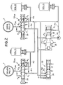
- Fig. 2 is a diagram showing a first embodiment of the hydraulic pressure control system of this invention in a belt type continuously variable transmission.
- Fig. 3. is a graph showing the hydraulic pressure output characteristic of a regulator valve.
- Figs. 4A and 4B are graphs showing hydraulic output characteristics of control valves.
- Fig. 5 is a diagram showing a second embodiment of the hydraulic control system of this invention in a belt type continuously variable transmission.
- Figs. 6A and 6B are enlarged views of the control valve shown in Fig. 5.
- Fig. 7 is a diagram showing a third embodiment of the hydraulic control system of this invention in a belt type continuously variable transmission.
- Fig. 8 is a graph showing a hydraulic output characteristic of the regulator valve.
- Figs. 9A and 9B are graphs showing hydraulic output characteristics of the control valves.
- Fig. 10A is a schematic diagram showing a conventional hydraulic control apparatus in a continuously variable transmission
- Figs. 10B and 10C are graphs illustrating the operating characteristics of the conventional hydraulic control apparatus of Fig. 10A.
- Fig. 1 illustrates a power transmission system to which each embodiment of the invention is applicable.
- the belt type continuously variable transmission T for a vehicle has an input shaft 1 and an output shaft 2 arranged in parallel, with a right end of a crank shaft 3 of the engine E connected to a left end of the input shaft 1 through a flywheel damper 4.
- a drive pulley 5 supported on the input shaft 1 has a stationary pulley half 5 1 rotatable relative to the input shaft 1 and a movable pulley half 5 2 axially slidable relative to the stationary pulley half 5 1 .
- the width of the groove formed between the movable pulley half 5 2 and the stationary pulley half 5 1 can be varied by an oil pressure acting on a hydraulic chamber 6.
- a driven pulley 7 supponed on the output shaft 2 has a stationary pulley half 7 1 fixed to or formed integral with the output shaft 2 and a movable pulley half 7 2 axially slidable relative to the stationary pulley half 7 1 .
- the width of the groove formed between the movable pulley half 7 2 and the stationary pulley half 7 1 can be varied by an oil pressure acting on a hydraulic chamber 8.
- An endless belt 9 comprising two strips of strap having a number of press pieces attached thereto is reeved around the drive pulley 5 and the driven pulley 7 to couple these pulleys.
- the right end of the input shaft 1 is provided with a forward-reverse changeover mechanism 12 in the form of a planetary gear system, which includes a forward clutch 10 that, when establishing a forward gear change, engages to transmit the rotation of the input shaft 1 in the same direction to the drive pulley 5 and a reverse brake 11 that, when establishing a reverse gear change, engages to transmit the rotation of the input shaft 1 in the reverse direction to the drive pulley 5.
- a forward clutch 10 that, when establishing a forward gear change, engages to transmit the rotation of the input shaft 1 in the same direction to the drive pulley 5
- a reverse brake 11 that, when establishing a reverse gear change, engages to transmit the rotation of the input shaft 1 in the reverse direction to the drive pulley 5.
- a startup clutch 13 is provided at the left end of the output shaft 2 and has a first intermediate gear 14 that is rotatably supported on the output shaft 2 connected to the stationary pulley half 7 1 of the driven pulley 7 that is fixed to the output shaft 2.
- On an intermediate shaft 15 arranged parallel to the output shaft 2 is mounted a second intermediate gear 16 that meshes with the first intermediate gear 14.
- a third intermediate gear 20 mounted on the intermediate shaft 15 meshes with an input gear 19 that is provided on a gear box 18 of a differential gear 17.
- a pair of pinions 52, 52 supported on the gear box 18 through pinion shafts 51 are meshed with side gears 55, 56 provided at the ends of a left axle 53 and a right axle 54, respectively, and both side gears are relatively rotatably supported on the gear box 18.
- the other ends of the left axle 53 and the right axle 54 are mounted with drive wheels W, W.
- An electronic control unit Ue receives signals from an accelerator opening sensor S 1 , an engine revolution sensor S 2 , an intake air negative pressure sensor S 3 , and the like. Based on the signals from these sensors S 1 -S 3 , the electronic control unit Ue outputs a control signal to a hydraulic control unit Uh, which then controls the groove widths of the drive pulley 5 and driven pulley 7, i.e., the gear ratio of the belt type continuously variable transmission T, the engagement condition of the forward clutch 10, the engagement condition of the reverse brake 11, and the engagement condition of the startup clutch 13.
- a planetary gear system 41 provided at the right end of the input shaft 1 comprises a sun gear 42 splined onto the input shaft 1; planetary carriers 43 1 , 43 2 formed of a pair of plates and rotatably supported on the input shaft 1; three inner pinions 44 rotatably supported on the planetary carriers 43 1 , 43 2 and meshing with the sun gear 42; three outer pinions 45 rotatably supported on the planetary carriers 43 1 , 43 2 and meshing with the inner pinions 44; a ring gear 46 meshing with the outer pinions 45; and a ring gear support member 47 supporting the ring gear 46 rotatably around an outer periphery of the input shaft 1.
- the electronic control unit Ue issues a control signal to engage the forward clutch 10, causing the input shaft 1 to be coupled to the drive pulley 5. This is followed by the engagement of the startup clutch 13 causing the torque of the engine E to be transmitted through the input shaft 1, drive pulley 5, endless belt 9, driven pulley 7, output shaft 2 and differential gear 17 to the drive wheels W, W, propelling the car forwardly.
- the electronic control unit Ue issues a control signal to engage the reverse brake 11, coupling the ring gear support member 47 and the ring gear 46 to the casing to hold them unrotatable.
- the inner pinions 44 and the outer pinions 45 are in mesh with the rotating sun gear 42 and the fixed ring gear 46 to move around input shaft 1 along with the planetary carriers 43 1 , 43 2 while rotating on their axes.
- the drive pulley 5 coupled to the planetary carriers 43 1 , 43 2 is driven with a reduced revolution speed, in a direction opposite to the rotating direction of the input shaft 1, thus driving the car rearwardly.
- the gear ratio can be adjusted continuously. That is, the oil pressure acting on the hydraulic chamber 8 of the driven pulley 7 is increased relative to the oil pressure acting on the hydraulic chamber 6 of the drive pulley 5 to reduce the groove width of the driven pulley 7 and thereby increase the effective radius of the driven pulley 7, which in turn causes the groove width of the drive pulley 5 to increase, reducing its effective radius.
- the gear ratio of the belt type continuously variable transmission T changes continuously toward the low-speed gear.
- the oil pressure delivered by an oil pump 57 is reduced by a regulator valve 22 to a PH pressure (line pressure), which is further reduced by a modulator valve 23 down to a PM pressure (modulator pressure).
- the PH pressure is regulated by a drive pulley control valve 24DR and supplied as a drive pulley pressure P DR to the hydraulic chamber 6 of the drive pulley 5.
- the PH pressure is also regulated by a driven pulley control valve 24 DN and supplied as a driven pulley pressure P DN to the hydraulic chamber 8 of the driven pulley 7.
- the regulator valve 22 has a spool 26 urged toward left by a spring 25.
- the delivery pressure of the oil pump 57 is regulated by the spool 26, which is actuated toward the left in response to an increase in a PA pressure supplied to a port P 1 of the regulator valve 22, and is output as the PH pressure from its port P 2 .
- the modulator valve 23 has a spool 28 urged toward the left by a spring 27 and reduces the PH pressure supplied from the regulator valve 22 to its port P 1 to output the reduced pressure as the PM pressure from its port P 2 .
- a solenoid valve SOL-A in the form of a bleed solenoid valve regulates the PM pressure from the modulator valve 23 and outputs the PA pressure that controls the regulator valve 22.
- the PH pressure changes linearly from 700 kPa to 3200 kPa.
- the drive pulley control valve 24 DR and the driven pulley control valve 24 DN have virtually the same structure, in which a spool 30 is urged toward the right by a spring 29.
- the PH pressure is supplied to the ports P 1 of the two control valves 24 DR , 24 DN while the ports P 2 are supplied either with a PB pressure, which is obtained by regulating the PM pressure by a solenoid valve SOL-B formed of a bleed solenoid valve, or with a PC pressure which is produced by regulating the PM pressure by a solenoid valve SOL-C formed of a bleed solenoid valve.
- PB pressure which is obtained by regulating the PM pressure by a solenoid valve SOL-B formed of a bleed solenoid valve
- PC pressure which is produced by regulating the PM pressure by a solenoid valve SOL-C formed of a bleed solenoid valve.
- Figure 4A shows change of the drive pulley pressure PDR according to change of the PB pressure.
- the drive pulley pressure P DR increases linearly from a PL pressure (PH pressure - ⁇ ) to the PH pressure.
- the PH pressure is variable and changes as the PA pressure output from the solenoid valve SOIL-A changes (see Figure 3).
- the characteristic of change of the driven pulley pressure P DN is identical with that of the drive pulley pressure P DR , as shown in Fig. 4B.
- the driven pulley pressure P DN increases linearly from the PL pressure (PH pressure - ⁇ ) to the PH pressure.
- the values ⁇ and ⁇ are constants and in this embodiment are both set at 1000 kPa.
- the three solenoid valves SOL-A, SOL-B, SOL-C are connected to and controlled by the electronic control unit Ue incorporating a microcomputer.
- both the PB pressure and the PC pressure output from the solenoid valves SOL-B, SOL-C are set to 0.
- the drive pulley pressure P DR transmitted to the hydraulic chamber 6 of the drive pulley 5 and the driven pulley pressure P DN transmitted to the hydraulic chamber 8 of the driven pulley 7 are both equal to the PL pressure (PH pressure - 1000 kPa), fixing the groove widths of the both pulleys 5, 7 thereby holding the gear ratio.
- the PB pressure output from the solenoid valve SOL-B needs to be increased from zero by applying a changing electric current thereto while maintaining the PC pressure output from the solenoid valve SOL-C at zero by applying a fixed electric current thereto.
- the drive pulley pressure P DR increases from the PL pressure toward the PH pressure with the driven pulley pressure P DN kept at the PL pressure (PH pressure - 1000 kPa), so that the movable pulley half 5 2 of the drive pulley 5 acted on by the PH pressure moves toward the stationary pulley half 5 1 to reduce the groove width, causing the movable pulley half 7 2 of the driven pulley 7 applied with the PL pressure to move away from the stationary pulley half 7 1 to increase the groove width, thereby changing the gear ratio from the low-speed gear toward the overdrive.
- the PC pressure output from the solenoid valve SOL-C needs to be increased from 0 while keeping the PB pressure output from the solenoid valve SOL-B at 0.
- the driven pulley pressure P DN increases from the PL pressure toward the PH pressure with the drive pulley pressure P DR kept at the PL pressure (PH pressure - 1000 kPa)
- the movable pulley half 7 2 of the driven pulley 7 applied with the PH pressure moves toward the stationary pulley half 7 1 to reduce the groove width, causing the movable pulley half 5 2 of the drive pulley 5 applied with the PL pressure to move away from the stationary pulley half 5 1 to increase the groove width, thereby changing the gear ratio from the overdrive toward the low-speed gear.
- the stability of the hydraulic control system is improved. Further, by setting the output pressure of one of the solenoid valves SOL-B, SOL-C to zero and changing the output pressure of the other solenoid valve to change the PL pressure with respect to the PH pressure, it is possible to set the pressure difference between the PH pressure and the PL pressure arbitrarily and thereby control the time required for the continuously variable transmission T to change gear ratio.
- the conventional four-way valve of the conventional system shown in Figs. 10A, 10B and 10C has a drawback that the dimensional control of an overlap between the spool groove and the valve body port is difficult and that the amount of change in the output pressure is large with respect to the spool stroke, making precise control difficult. Because the four-way valve is eliminated, this problem is solved with this embodiment of the invention. Further, when electricity to the solenoid valves SOL-A, SOL-B, SOL-C is cut off in the event of a failure in the control system, the gear ratio of the belt type continuously variable transmission T can be held as it is and prevented from changing rapidly toward the overdrive or the low-speed gear.
- FIGs. 5, 6A and 6B show a second embodiment of this invention, with Figure 5 representing a hydraulic control system of the belt type continuously variable transmission and Figures 6A and 6B representing enlarged cross sectional views of the control valves 24 DR and 24 DN .
- the second embodiment differs from the first embodiment in the construction of the drive pulley control valve 24 DR and the driven pulley control valve 24 DN that cause the pulley pressures P DR , P DN to follow PH pressure changes.
- Other structures of the system are virtually identical with those of the first embodiment. Since the two control valves 24 DR , 24 DN are identical in structure, only the drive pulley control valve 24 DR will be explained.
- Figure 6A shows the drive pulley control valve 24 DR of the first embodiment, in which the port P 1 and port P 4 are supplied with the PH pressure, the port P 2 with the PB pressure, the port P 5 with the pulley pressure P DR , and the port P 3 outputs the pulley pressure P DR .
- the PH pressure entering the port P 4 urges the spool 30 toward the left
- the pulley pressure P DR entering the port P 5 urges the spool 30 toward the right.
- the pressure receiving area of the spool 30 acted on by the PH pressure is A 1 and the pressure receiving area of the spool 30 acted on by the pulley pressure P DR is A 2 .
- the second embodiment of the hydraulic control system has the port P 4 ' supplied with the PA pressure output from the solenoid valve SOL-A instead of the PH pressure. That is, the second embodiment differs from the first embodiment in that the PA pressure, rather than the PH pressure used in the first embodiment, is supplied to the port P 4 ' to cause the pulley pressure P DR to follow the PH pressure change.
- the PH pressure output from the regulator valve 22 may become lower than the set value regardless of the value of the control signal output from the electronic control unit Ue to the solenoid valve SOL-A (i.e., output pressure of the solenoid valve SOL-A to the regulator valve 22).
- the PH pressure is supplied to the port P 4 ' of the control valve 24 DR to cause the pulley pressure P DR to automatically follow the PH pressure change, as in the first embodiment, there is a possibility of the pulley pressure P DR becoming lower than the PL pressure as it follows the PH pressure that has gone below the set value.
- the PA pressure supplied to the port P 4 ' of the control valve 24 DR uses as a source pressure the PM pressure that is lower than the PH pressure and thus the above trouble can be avoided.
- the PM pressure which is lower than the PH pressure
- the PA pressure which is based on the PM pressure, at the set value.
- changing the pulley pressure P DR based on the PA pressure can prevent the pulley pressure P DR from decreasing below the PL pressure as the PH pressure lowers.
- Figures 7, 8, 9A and 9B represent a third embodiment of this invention, with Figure 7 showing a hydraulic control system of the belt type continuously variable transmission, Figure 8 a graph of hydraulic output characteristic of the regulator valve, and Figures 9A and 9B graphs of hydraulic output characteristics of the control valves.
- the hydraulic circuit of the third embodiment resembles that of the second embodiment (see Figure 5), except that the characteristics of the regulator valve 22 and the control valves 24 DR , 24 DN differ from those of the second embodiment and that three-way duty solenoid valves are employed as the solenoid valves SOL-B, SOL-C instead of the bleed solenoid valves.
- the line pressure PH produced by the regulator valve 22 is supplied to the ports P 1 , P 1 of the both control valves 24 DR , 24 DN .
- the PA pressure produced by the solenoid valve SOL-A based on the PM pressure output from the modulator valve 23 is supplied to the port P 1 of the regulator valve 22 and to the ports P 4 ', P 4 ' of both the control valves 24 DR , 24 DN , and the PB pressure and the PC pressure produced by the solenoid valves SOL-B, SOL-C, respectively, based on the PM pressure, are supplied to the ports P 2 ', P 2 ' of the control valves 24 DR , 24 DN .
- the line pressure produced by the regulator valve 22 is the PL pressure plus a predetermined pressure difference (described later, 1000 kPa in this embodiment) and is controlled by the PA pressure output from the solenoid valve SOL-A. As shown in Figure 8, when the PA pressure changes from 0 kPA to 500 kPA, the line pressure PH changes linearly from 1300 kPA to 3500 kPA.
- the control valves 24 DR , 24 DN regulate the line pressure, as a source pressure, to produce the pulley pressures P DR , P DN .
- the control valves 24 DR , 24 DN produce the PL pressure when the PB pressure or PC pressure output from the solenoid valve SOL-B, SOL-C, respectively, is 0 kPa and, when the PB or PC pressure is 450 kPa, produce the line pressure (PL pressure + pressure difference).
- the line pressure (PL pressure + pressure difference) and the pulley pressures P DR , P DN (PL pressure) change according to the PA pressure change, during which time the pressure difference is kept constant (at 1000 kPa).
- the pressure difference decreases from 1000 kPa to 0 kPa, causing the pulley pressures P DR , P DN to rise to the line pressure (PL pressure + pressure difference).
- the PB and PC pressures produced by the solenoid valves SOL-B, SOL-C are both set to zero.
- the drive pulley pressure P DR applied to the hydraulic chamber 6 of the drive pulley 5 and the driven pulley pressure P DN applied to the hydraulic chamber 14 of the driven pulley 7 are both equal to the PL pressure, fixing the widths of the grooves of both pulleys 5, 7 and thus holding the gear ratio.
- the PA pressure produced by the solenoid valve SOL-A is reduced to lower the PL pressure, it is possible to reduce the load of the oil pump 57 and therefore the fuel consumption while holding the gear ratio of the belt type continuously variable transmission T.
- the PB pressure produced by the solenoid valve SOL-B needs only to be increased from zero while maintaining the PC pressure produced by the solenoid valve SOL-C at zero. This causes the drive pulley pressure P DR to increase from the PL pressure toward the line pressure (PL pressure + pressure difference) with the driven pulley pressure P DN kept at the PL pressure, thus changing the gear ratio from the low-speed gear toward the overdrive.
- the PC pressure produced by the solenoid valve SOL-C needs to be increased from zero while holding the PB pressure produced by the solenoid valve SOL-B at zero.
- the driven pulley pressure P DN rises from the PL pressure toward the line pressure (PL pressure + pressure differential) with the drive pulley pressure P DR kept at the PL pressure, thereby causing the gear ratio to change from the overdrive toward the low-speed gear.
- the accuracy of the low PL pressure is more important than that of the high PH pressure, these pressures working as the pulley pressures P DR , P DN .
- the PH pressure produced by the regulator valve 22 is reduced by the control valves 24 DR , 24 DN by the pressure difference to output the PL pressure, the errors in the PH pressure caused by PA pressure variations output from the solenoid valve SOL-A and the errors in the pressure difference caused by PB or PC pressure variations output from the solenoid valve SOL-B, SOL-C combine to reduce the accuracy of the PL pressure, although still more accurate than the prior art system.
- the control precision is not degraded by variations of the PB or PC pressure.
- the PH pressure is affected by variations of the PA pressure and by variations of the PB or PC pressure and its accuracy is degraded, because the PH pressure does not require as high an accuracy as the PL pressure, the degraded accuracy of the PH pressure does not practically pose any problem.
- the solenoid valves SOL-B, SOL-C can use three-way duty solenoid valves (see Figure 7) with relatively low precision, instead of the high-precision bleed solenoid valves.
- the three-way duty solenoid valve has a feature that it has a significantly smaller oil leakage than that of the bleed solenoid valve, which in turn reduces the load of the oil pump 57 and also prevents a fall of the line pressure when the engine revolution speed is reduced.
- this hydraulic control apparatus it is possible to change the pressure difference between the drive pulley pressure and the driven pulley pressure according to changes in the electric current values to control the speed change time.
- the drive pulley pressure and the driven pulley pressure are controlled independently by the first control valve and the second control valve, the stability of the hydraulic control system is improved.
- the first solenoid valve and the second solenoid valve are not activated simultaneously, the load on the control means is alleviated.
- Another advantage is that because the conventional four-way valve can be eliminated, whose overlap dimension between the spool groove and the valve body port is difficult to control and whose output pressure change is sharp with respect to the spool stroke, a precise control of the pulley pressure can be accomplished.
- the line pressure produced by the regulator valve is regulated by the third control pressure output from the third solenoid valve, it is possible to lower the line pressure and therefore the hydraulic load when the electric currents of the first solenoid valve and the second solenoid valve are held to fix the gear ratio.
- a change in the line pressure output from the regulator valve is made proportional to a change in the third control pressure, which is lower than the line pressure, and the spools of the first and second control valves are urged in opposite directions by the pulley pressure and the third control pressure and held at balanced positions, it is possible to reduce an oil leakage by using the third control pressure, which is lower than the line pressure, as a hydraulic pressure for holding the spools in the balanced positions and causing the change in the pulley pressure to follow the change in the line pressure.
- the pulley pressure produced by a control valve which is controlled by a solenoid valve whose supplied electric current is fixed, is a low-pressure side pulley pressure and the pulley pressure produced by a control valve, which is controlled by a solenoid valve whose supplied electric current is changed, is a high-pressure side pulley pressure that has a pressure difference with respect to the low-pressure side pulley pressure, whereby the pressure difference corresponds to the changing solenoid valve current.
Landscapes
- Engineering & Computer Science (AREA)
- General Engineering & Computer Science (AREA)
- Mechanical Engineering (AREA)
- Control Of Transmission Device (AREA)
Applications Claiming Priority (3)
| Application Number | Priority Date | Filing Date | Title |
|---|---|---|---|
| JP27025696A JP3640477B2 (ja) | 1996-10-11 | 1996-10-11 | 無段変速機における油圧制御装置 |
| JP27025696 | 1996-10-11 | ||
| JP270256/96 | 1996-10-11 |
Publications (3)
| Publication Number | Publication Date |
|---|---|
| EP0841504A2 true EP0841504A2 (fr) | 1998-05-13 |
| EP0841504A3 EP0841504A3 (fr) | 1999-12-08 |
| EP0841504B1 EP0841504B1 (fr) | 2003-04-09 |
Family
ID=17483721
Family Applications (1)
| Application Number | Title | Priority Date | Filing Date |
|---|---|---|---|
| EP97308037A Expired - Lifetime EP0841504B1 (fr) | 1996-10-11 | 1997-10-10 | Dispositif hydraulique de commande d'une transmission à variation continue |
Country Status (4)
| Country | Link |
|---|---|
| US (1) | US5888168A (fr) |
| EP (1) | EP0841504B1 (fr) |
| JP (1) | JP3640477B2 (fr) |
| DE (1) | DE69720648T2 (fr) |
Cited By (5)
| Publication number | Priority date | Publication date | Assignee | Title |
|---|---|---|---|---|
| DE10017402A1 (de) * | 2000-04-07 | 2001-10-18 | Zahnradfabrik Friedrichshafen | Anordnung zur Betätigung eines Kraftfahrzeug-Umschlingungsgetriebes |
| EP1217266A1 (fr) * | 2000-12-21 | 2002-06-26 | Van Doorne's Transmissie B.V. | Système de commande pour transmission à variation continue |
| EP1070877A3 (fr) * | 1999-07-23 | 2003-09-24 | Honda Giken Kogyo Kabushiki Kaisha | Système de commande d'un boíte de vitesses pour véhicules |
| WO2007013792A1 (fr) * | 2005-07-27 | 2007-02-01 | Robert Bosch Gmbh | Procede de commande d'une transmission a variation continue |
| US9556953B2 (en) | 2012-12-27 | 2017-01-31 | Robert Bosch Gmbh | Hydraulically actuated continuously variable transmission |
Families Citing this family (12)
| Publication number | Priority date | Publication date | Assignee | Title |
|---|---|---|---|---|
| JP3552411B2 (ja) * | 1996-07-16 | 2004-08-11 | 日産自動車株式会社 | Vベルト式無段変速機 |
| DE19721027A1 (de) * | 1997-05-20 | 1998-11-26 | Bosch Gmbh Robert | Hydrauliknotsteuerung zur Einstellung eines konstanten Klemmverhältnisses bei einem stufenlos verstellbaren Umschlingungsgetriebe |
| JP3955369B2 (ja) * | 1997-10-23 | 2007-08-08 | 富士重工業株式会社 | 自動変速装置 |
| DE19914931B4 (de) * | 1999-04-01 | 2007-12-13 | Zf Friedrichshafen Ag | Vorrichtung zum Steuern eines CVT |
| JP3654072B2 (ja) * | 1999-08-25 | 2005-06-02 | 三菱自動車工業株式会社 | ベルト式無段変速機の油圧回路 |
| US6669598B2 (en) * | 2002-02-19 | 2003-12-30 | General Motors Corporation | Line pressure control for a continuously variable transmission |
| WO2004024524A1 (fr) * | 2002-09-04 | 2004-03-25 | Luk Lamellen Und Kupplungsbau Beteiligungs Kg | Procede et dispositif pour controler des signaux de freinage sur un vehicule |
| JP4671750B2 (ja) * | 2005-04-27 | 2011-04-20 | 富士重工業株式会社 | 無段変速機の変速制御装置 |
| JP4799967B2 (ja) * | 2005-09-06 | 2011-10-26 | 富士重工業株式会社 | 無段変速機の変速制御装置 |
| JP4745765B2 (ja) * | 2005-09-06 | 2011-08-10 | 富士重工業株式会社 | 無段変速機の変速制御装置 |
| JP5405863B2 (ja) * | 2009-03-23 | 2014-02-05 | 富士重工業株式会社 | 無段変速機の制御装置 |
| DE112015006318T5 (de) * | 2015-03-18 | 2017-12-21 | GM Global Technology Operations LLC | Stufenloses Getriebe und Verfahren zum Steuern desselben |
Family Cites Families (10)
| Publication number | Priority date | Publication date | Assignee | Title |
|---|---|---|---|---|
| US4387608A (en) * | 1979-09-12 | 1983-06-14 | Robert Bosch Gmbh | Electronic control for a stepless vehicle transmission using a control member response to dynamic pressure |
| JPS60222649A (ja) * | 1984-04-19 | 1985-11-07 | 富士重工業株式会社 | 電子式無段変速機の変速比制御装置 |
| JPS624647A (ja) * | 1985-06-29 | 1987-01-10 | Fuji Heavy Ind Ltd | 無段変速機の制御装置 |
| JPS6231761A (ja) * | 1985-08-02 | 1987-02-10 | Toyota Central Res & Dev Lab Inc | 無段変速機の速度比制御装置 |
| JPH0674839B2 (ja) * | 1985-11-29 | 1994-09-21 | 株式会社豊田中央研究所 | 無段変速機用油圧制御装置 |
| US4854920A (en) * | 1986-08-26 | 1989-08-08 | Mitsubishi Denki Kabushiki Kaisha | Control device of non-stage transmission |
| US5062050A (en) * | 1989-10-17 | 1991-10-29 | Borg-Warner Automotive, Inc. | Continuously variable transmission line pressure control |
| JPH05126239A (ja) * | 1991-06-29 | 1993-05-21 | Mazda Motor Corp | 車両用無段変速機の変速制御装置 |
| BE1007289A3 (nl) * | 1993-07-14 | 1995-05-09 | Vcst Nv | Werkwijze voor het regelen van een transmissie-eenheid bij motorvoertuigen en transmissie-eenheid die deze werkwijze toepast. |
| DE19533976A1 (de) * | 1995-09-14 | 1997-03-20 | Zahnradfabrik Friedrichshafen | Hydraulisches System für ein CVT |
-
1996
- 1996-10-11 JP JP27025696A patent/JP3640477B2/ja not_active Expired - Fee Related
-
1997
- 1997-10-10 DE DE69720648T patent/DE69720648T2/de not_active Expired - Fee Related
- 1997-10-10 EP EP97308037A patent/EP0841504B1/fr not_active Expired - Lifetime
- 1997-10-14 US US08/949,978 patent/US5888168A/en not_active Expired - Fee Related
Non-Patent Citations (1)
| Title |
|---|
| None |
Cited By (8)
| Publication number | Priority date | Publication date | Assignee | Title |
|---|---|---|---|---|
| EP1070877A3 (fr) * | 1999-07-23 | 2003-09-24 | Honda Giken Kogyo Kabushiki Kaisha | Système de commande d'un boíte de vitesses pour véhicules |
| DE10017402A1 (de) * | 2000-04-07 | 2001-10-18 | Zahnradfabrik Friedrichshafen | Anordnung zur Betätigung eines Kraftfahrzeug-Umschlingungsgetriebes |
| US6537176B2 (en) | 2000-04-07 | 2003-03-25 | Zf Batavia L.L.C. | Arrangement for operating an automotive CVT |
| EP1217266A1 (fr) * | 2000-12-21 | 2002-06-26 | Van Doorne's Transmissie B.V. | Système de commande pour transmission à variation continue |
| US6679805B2 (en) | 2000-12-21 | 2004-01-20 | Van Doorne's Transmissie Bv | Control system and continuously variable transmission provided therewith |
| WO2007013792A1 (fr) * | 2005-07-27 | 2007-02-01 | Robert Bosch Gmbh | Procede de commande d'une transmission a variation continue |
| CN101273223B (zh) * | 2005-07-27 | 2012-07-04 | 罗伯特·博世有限公司 | 用于操作无级变速装置的方法 |
| US9556953B2 (en) | 2012-12-27 | 2017-01-31 | Robert Bosch Gmbh | Hydraulically actuated continuously variable transmission |
Also Published As
| Publication number | Publication date |
|---|---|
| EP0841504A3 (fr) | 1999-12-08 |
| US5888168A (en) | 1999-03-30 |
| DE69720648D1 (de) | 2003-05-15 |
| JP3640477B2 (ja) | 2005-04-20 |
| EP0841504B1 (fr) | 2003-04-09 |
| DE69720648T2 (de) | 2003-10-30 |
| JPH10115354A (ja) | 1998-05-06 |
Similar Documents
| Publication | Publication Date | Title |
|---|---|---|
| EP0841504B1 (fr) | Dispositif hydraulique de commande d'une transmission à variation continue | |
| EP0177241B1 (fr) | Transmission variable continûment | |
| US3969958A (en) | Output split type hydrostatic transmission | |
| EP0733831B1 (fr) | Transmission à variation continue | |
| US5088352A (en) | System for controlling hydraulic fluid pressure for V-belt type automatic transmission | |
| EP0733829A2 (fr) | Transmission à variation continue | |
| US6299564B1 (en) | Hydraulic control system for a CVT | |
| US5045028A (en) | Cone disk transmission, especially for motor vehicles | |
| EP0140355A1 (fr) | Méthode et appareil pour contrôler une transmisson à courroie trapézoidale continue avec commande hydraulique | |
| JP3524751B2 (ja) | 変速機の油圧制御装置 | |
| US4904229A (en) | Belt-and-pulley type continuously variable transmission and method for controlling the same | |
| US5512021A (en) | Variable ratio transmission | |
| JPH02120568A (ja) | 流体継手のスリップ制御装置 | |
| US5089964A (en) | Hydraulic transmission control system | |
| US20050107195A1 (en) | Belt-type continuously variable transmission | |
| US5063815A (en) | Line pressure control for V-belt type continuously variable transmission | |
| US4660438A (en) | Continuously variable transmission | |
| US5813933A (en) | Continuously variable transmission with bias springs on the drive and driven pulleys for setting a predetermined speed ratio when the cut is in neutral | |
| JP3211697B2 (ja) | 無段変速機の目標変速比生成装置 | |
| US4871343A (en) | Belt-and-pulley type continuously variable transmission | |
| CA2475453C (fr) | Transmission a orbiteur minimal | |
| US6939261B1 (en) | Compact vehicle transmission | |
| JP3613641B2 (ja) | 無段変速機 | |
| JPH04285361A (ja) | 車両用ベルト式無段変速機の制御装置 | |
| JP3216286B2 (ja) | 車両用ベルト式無段変速機の油圧制御装置 |
Legal Events
| Date | Code | Title | Description |
|---|---|---|---|
| PUAI | Public reference made under article 153(3) epc to a published international application that has entered the european phase |
Free format text: ORIGINAL CODE: 0009012 |
|
| AK | Designated contracting states |
Kind code of ref document: A2 Designated state(s): DE FR GB |
|
| AX | Request for extension of the european patent |
Free format text: AL;LT;LV;RO;SI |
|
| PUAL | Search report despatched |
Free format text: ORIGINAL CODE: 0009013 |
|
| AK | Designated contracting states |
Kind code of ref document: A3 Designated state(s): AT BE CH DE DK ES FI FR GB GR IE IT LI LU MC NL PT SE |
|
| AX | Request for extension of the european patent |
Free format text: AL;LT;LV;RO;SI |
|
| 17P | Request for examination filed |
Effective date: 20000222 |
|
| 17Q | First examination report despatched |
Effective date: 20000417 |
|
| AKX | Designation fees paid |
Free format text: DE FR GB |
|
| GRAG | Despatch of communication of intention to grant |
Free format text: ORIGINAL CODE: EPIDOS AGRA |
|
| GRAG | Despatch of communication of intention to grant |
Free format text: ORIGINAL CODE: EPIDOS AGRA |
|
| GRAH | Despatch of communication of intention to grant a patent |
Free format text: ORIGINAL CODE: EPIDOS IGRA |
|
| GRAH | Despatch of communication of intention to grant a patent |
Free format text: ORIGINAL CODE: EPIDOS IGRA |
|
| GRAA | (expected) grant |
Free format text: ORIGINAL CODE: 0009210 |
|
| AK | Designated contracting states |
Designated state(s): DE FR GB |
|
| REG | Reference to a national code |
Ref country code: GB Ref legal event code: FG4D |
|
| PGFP | Annual fee paid to national office [announced via postgrant information from national office to epo] |
Ref country code: DE Payment date: 20030829 Year of fee payment: 7 |
|
| PGFP | Annual fee paid to national office [announced via postgrant information from national office to epo] |
Ref country code: GB Payment date: 20031007 Year of fee payment: 7 |
|
| PGFP | Annual fee paid to national office [announced via postgrant information from national office to epo] |
Ref country code: FR Payment date: 20031027 Year of fee payment: 7 |
|
| ET | Fr: translation filed | ||
| PLBE | No opposition filed within time limit |
Free format text: ORIGINAL CODE: 0009261 |
|
| STAA | Information on the status of an ep patent application or granted ep patent |
Free format text: STATUS: NO OPPOSITION FILED WITHIN TIME LIMIT |
|
| 26N | No opposition filed |
Effective date: 20040112 |
|
| PG25 | Lapsed in a contracting state [announced via postgrant information from national office to epo] |
Ref country code: GB Free format text: LAPSE BECAUSE OF NON-PAYMENT OF DUE FEES Effective date: 20041010 |
|
| PG25 | Lapsed in a contracting state [announced via postgrant information from national office to epo] |
Ref country code: DE Free format text: LAPSE BECAUSE OF NON-PAYMENT OF DUE FEES Effective date: 20050503 |
|
| GBPC | Gb: european patent ceased through non-payment of renewal fee |
Effective date: 20041010 |
|
| PG25 | Lapsed in a contracting state [announced via postgrant information from national office to epo] |
Ref country code: FR Free format text: LAPSE BECAUSE OF NON-PAYMENT OF DUE FEES Effective date: 20050630 |
|
| REG | Reference to a national code |
Ref country code: FR Ref legal event code: ST |