EP0843387B1 - Structure d'assemblage de connecteur - Google Patents
Structure d'assemblage de connecteur Download PDFInfo
- Publication number
- EP0843387B1 EP0843387B1 EP97119740A EP97119740A EP0843387B1 EP 0843387 B1 EP0843387 B1 EP 0843387B1 EP 97119740 A EP97119740 A EP 97119740A EP 97119740 A EP97119740 A EP 97119740A EP 0843387 B1 EP0843387 B1 EP 0843387B1
- Authority
- EP
- European Patent Office
- Prior art keywords
- connector
- provisionally
- retaining
- connection
- holder
- Prior art date
- Legal status (The legal status is an assumption and is not a legal conclusion. Google has not performed a legal analysis and makes no representation as to the accuracy of the status listed.)
- Expired - Lifetime
Links
- 230000007246 mechanism Effects 0.000 claims description 44
- 238000006073 displacement reaction Methods 0.000 description 9
- 230000000717 retained effect Effects 0.000 description 4
- 230000000670 limiting effect Effects 0.000 description 2
- 230000005405 multipole Effects 0.000 description 2
- 230000002441 reversible effect Effects 0.000 description 2
- 238000004378 air conditioning Methods 0.000 description 1
- 238000013459 approach Methods 0.000 description 1
- 230000015572 biosynthetic process Effects 0.000 description 1
- 239000004020 conductor Substances 0.000 description 1
- 230000003247 decreasing effect Effects 0.000 description 1
- 230000005764 inhibitory process Effects 0.000 description 1
- 238000003780 insertion Methods 0.000 description 1
- 230000037431 insertion Effects 0.000 description 1
- 238000004519 manufacturing process Methods 0.000 description 1
- 230000013011 mating Effects 0.000 description 1
- 230000002829 reductive effect Effects 0.000 description 1
- 238000005476 soldering Methods 0.000 description 1
Images


Classifications
-
- H—ELECTRICITY
- H01—ELECTRIC ELEMENTS
- H01R—ELECTRICALLY-CONDUCTIVE CONNECTIONS; STRUCTURAL ASSOCIATIONS OF A PLURALITY OF MUTUALLY-INSULATED ELECTRICAL CONNECTING ELEMENTS; COUPLING DEVICES; CURRENT COLLECTORS
- H01R13/00—Details of coupling devices of the kinds covered by groups H01R12/70 or H01R24/00 - H01R33/00
- H01R13/62—Means for facilitating engagement or disengagement of coupling parts or for holding them in engagement
- H01R13/629—Additional means for facilitating engagement or disengagement of coupling parts, e.g. aligning or guiding means, levers, gas pressure electrical locking indicators, manufacturing tolerances
- H01R13/62933—Comprising exclusively pivoting lever
- H01R13/62966—Comprising two pivoting levers
- H01R13/62972—Wherein the pivoting levers are two lever plates
-
- H—ELECTRICITY
- H01—ELECTRIC ELEMENTS
- H01R—ELECTRICALLY-CONDUCTIVE CONNECTIONS; STRUCTURAL ASSOCIATIONS OF A PLURALITY OF MUTUALLY-INSULATED ELECTRICAL CONNECTING ELEMENTS; COUPLING DEVICES; CURRENT COLLECTORS
- H01R13/00—Details of coupling devices of the kinds covered by groups H01R12/70 or H01R24/00 - H01R33/00
- H01R13/62—Means for facilitating engagement or disengagement of coupling parts or for holding them in engagement
- H01R13/629—Additional means for facilitating engagement or disengagement of coupling parts, e.g. aligning or guiding means, levers, gas pressure electrical locking indicators, manufacturing tolerances
- H01R13/62933—Comprising exclusively pivoting lever
- H01R13/62938—Pivoting lever comprising own camming means
Definitions
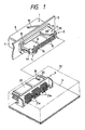
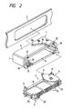
- a sliding connection-type electric connector (as disclosed in Japanese Patent Unexamined Publication No. 4-319271) comprising a holder (slide member) which supports a first connector inserted therein, and has a plurality of engagement projections formed on upper and lower wall surfaces thereof, a second connector of a generally rectangular shape which has a recess for receiving the holder, and openings generally parallel to side walls thereof, and an operating member of a generally U-shape having a cam groove for engagement with the engagement projection of the holder, and the first and second connectors are connected together by sliding the operating member.
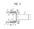
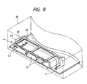
- This guide groove 10 has an introduction portion 10a extending rearwardly from the front side of the holder 1, a drive groove portion 10b of an arcuate shape extending rearwardly inwardly from a rear end of the introduction portion 10a, and a retaining groove portion 10c extending rearwardly from a rear end of the drive groove portion 10b.
- the drive groove portion 10b of the guide groove 10 and the engagement pin 9 cooperate with each other to provide a drive portion which swingingly displaces the swingable lever 5 in accordance with a sliding displacement of the first connector 2 as described later.
- provisionally-retaining mechanisms 41 which provisionally retain the first connector 2 in the connection stand-by position so as to prevent the first connector 2 from being forced into the holder 1 before a connection operation (described later) is effected.
- draw drive mechanisms 42 which draw the first connector 2 into the connection stand-by position when the connection between the first and second connectors 2 and 4 is to be released.
- Retaining portions 43 for retaining the respective draw drive mechanisms 42 in a draw-driven condition are provided at the second connector 4.
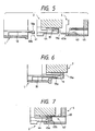
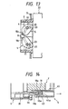
- a tapering (inwardly slanting) surface 19a is formed at the step portion 19 of the connector housing 14, and when releasing the connection, the tapering surface 19a abuts against a rear end of the provisionally-retaining projection 18a to swingingly displace the provisionally-retaining arm 18 inwardly.
- the two engagement projections 44a and 45a have respective pairs of slanting (tapering) surfaces which swingingly displace the distal end portion of the first engagement arm 44 outwardly to bring the engagement projections 44a and 45a into engagement with each other when connecting the two connectors 2 and 4 together, and swingingly displace the distal end portion of the first engagement arm 45 to release the engagement between the engagement projections 44a and 45a when releasing the connection between the connectors 2 and 4.
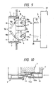
- An engagement groove 25 is formed in the reverse (inner) surface of each swingable lever 5 5 (that is, the lower surface of the upper swingable lever 5, and the upper surface of the lower swingable lever 5) at a front end portion thereof, and the driven pins 23, formed on the connector housing 20 of the second connector 4, are engageable in the engagement grooves 25, respectively.
- the engagement groove 25 in the swingable lever 5 has an opening portion 25a serving as an introduction portion for the driven pin 23, and an operating groove portion 25b continuously extending rearwardly from the opening portion 25a toward the inner side of the swingable lever 5.
- the distance from the operating groove portion 25b to the swing pivot 11 is decreasing progressively from its front end toward its rear end, and with this arrangement the operating groove portion 25b and the driven pin 23 of the second connector 4 cooperate with each other to provide an operating portion which transmits a driving force, inputted to the swingable lever 5 from the above-mentioned drive portion, to the second connector 4, thereby moving the second connector 4 in a direction to connect the same to the first connector 2.
- the distance from the operating groove portion 25b to the swing pivot 11 is so determined that the operating groove portion 25b approaches the swing pivot 11 progressively from its front end toward its rear end, and with this arrangement when the first and second connectors 2 and 4 are to be connected together, the first connector 2 is forced or pushed into the holder 1 to be slidingly displaced, and in accordance with this sliding displacement of the first connector 2, each driven pin 23 is drawn toward the associated swing pivot 11, thereby moving the second connector 4 toward the first connector 2.
- the position of the drive groove portion 10b of each guide groove 10 relative to the associated swing pivot 11, the position of the operating groove portion 25b of each engagement groove 25 relative to the associated swing pivot 11, and their configurations are so determined that the amount of movement of the second connector 4 in the above connecting direction is smaller than the amount of pushing of the first connector 2 into the holder 1.
- the driving force, inputted to the swingable lever 5 from the drive portion is increased, and is transmitted to the driven pin 23 of the second connector 4 from the operating groove portion 25b.
- the amount of movement of the second connector 4 driven by the swingable levers 5 in the connecting direction is smaller than the amount of displacement of the first connector 2 which swingingly displaces the swingable levers 5, and therefore the driving force, inputted to each swingable lever 5 from the drive portion, is increased, and is transmitted to the associated driven pin 23 from the operating groove portion 25b.
- the second connector 4 is pushed toward the first connector 2 with a large force, so that the first connector 2 and the second connector 4 are positively connected together.
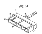
- the electronic unit 22 For releasing the connection between the first connector 2 and the second connector 4, the electronic unit 22 is pulled to slidingly displace the second connector 4 into the connection release position, so that the swingable levers 5 are swingingly displaced in directions opposite to the swinging directions during the connecting operation, and the swingable levers 5 and the first connector 2 are slidingly displaced forwardly, and then the two connectors 2 and 4 are disconnected from each other.
- the first connector 2 is provisionally retained in the front connection stand-by position by the provisionally-retaining mechanisms 41 each comprising the provisionally-retaining arm 18 of the holder 1 and the step portion 19 of the first connector 2, and this provisionally-retained condition is released when the first and second connectors 2 and 4 are to be connected together.
- the draw drive mechanisms 42 which draw the first connector 2 to the connection stand-by position when releasing the connection between the first and second connectors 2 and 4, are provided between the first and second connectors 2 and 4, and therefore when releasing the connection between the first and second connectors 2 and 4 by pulling the second connector 4 connected to the first connector 2, the first connector 2 can be slidingly displaced to the front side of the holder 1 by the draw drive mechanisms 42 each comprising the first engagement arm 44 and the second engagement arm 45, and the first connector 2 can be automatically returned to the front connection stand-by position.
- provisional retainment release mechanisms each comprising the projection 18a of the provisionally-retaining arm 18 and the retaining portion 43 of the second connector 4, and when connecting the first and second connectors 2 and 4 together, the provisionally-retaining mechanism 41 is driven by this provisional retainment release mechanism, thereby forcibly releasing the provisionally-retained condition of the first connector 2.
- the swingable lever 5 is provided on only one of the upper and lower sides of the first connector 2, or there may be provided a structure in which a pair of right and left swingable levers 5 are provided on each of the upper and lower sides of the first connector 2. Where the pair of swingable levers 5 are provided on each side, the directions of swinging motion of these levers do not always need to be opposite, but the two swingable levers 5 may be swingingly displaceable in the same direction.
- the retaining step portion 12 has the slanting surface 12c formed at its inner surface, and has the tapering configuration, and the slit 12a is provided between the horizontal plate 6 of the holder 1 and each retaining portion 12, and each projection 17 on the connector housing 14 can be pressed against the slanting surface 12c of the associated retaining step portion 12b to elastically deform the retaining portion 12.
- the connection of the first connector 2 to the holder 1 can be easily effected with one touch.
- the first connector 2 can be withdrawn outwardly from the holder 1.
- each of the guide grooves 10 in the holder 1 has the retaining groove portion 10c so that at the final stage of the connection of the second connector 4 to the first connector 2, the first connector 2 and the second connector 4 cab be slidingly displaced in unison in the holder 1, there may be provided a structure in which a retaining groove portion 25c of an arcuate shape, which is equidistant from the swing pivot 11 of the swingable lever 5 throughout its length, extends continuously from the operating groove portion 25b of the engagement groove 25, as shown in Fig. 16.
Landscapes
- Details Of Connecting Devices For Male And Female Coupling (AREA)
- Manufacturing Of Electrical Connectors (AREA)
Claims (7)
- Structure d'assemblage de connecteurs comprenant:caractérisée parun premier connecteur (2) introduit dans et supporté sur un support (1) ;un second connecteur (4) pour un assemblage audit premier connecteur (2) ;un mécanisme de retenue provisoire (41) monté entre ledit premier connecteur (2) et ledit support (1) afin de retenir provisoirement ledit premier connecteur (2) dans une position d'attente d'assemblage de manière à empêcher le premier connecteur (2) d'être poussé dans le support ; lors de l'assemblage desdits premier et second connecteurs, la condition de retenue provisoire dudit premier connecteur (2) est supprimée par un mécanisme de suppression de retenue provisoire (18b, 43), de sorte que ledit premier connecteur (2) peut être déplacé par glissement dans une position d'assemblage ;
un mécanisme de traction (42) formé par des bras d'engagement sur lesdits premier et second connecteurs s'engageant l'un avec l'autre dans une condition de traction, et monté entre lesdits premier et second connecteurs pour tirer ledit premier connecteur (2) dans ladite position d'attente d'assemblage lors de la suppression de l'assemblage entre lesdits premier et second connecteurs en tirant le second connecteur (4) dans une direction de dégagement d'assemblage ; et
une partie de retenue (43) prévue dans ledit second connecteur (4), qui maintient une condition de traction dudit premier connecteur (2), obtenue par ledit mécanisme de traction (42), avant que ledit premier connecteur (2) soit tiré dans ladite position d'attente d'assemblage par ledit mécanisme de traction (42), et permet également à la condition de traction dudit premier connecteur (2) d'être supprimée lorsque ledit premier connecteur (2) est tiré dans ladite position d'attente d'assemblage. - Structure d'assemblage de connecteurs selon la revendication 1, dans laquelle ledit mécanisme de suppression de retenue provisoire (18b, 43), lors de l'assemblage desdits premier et second connecteurs, déplace ledit mécanisme de retenue provisoire (41) de manière à supprimer de force la condition de retenue provisoire dudit premier connecteur (2).
- Structure d'assemblage de connecteurs selon la revendication 1, dans laquelle ledit mécanisme de retenue provisoire (41) comprend un bras de retenue provisoire (18) faisant saillie vers l'avant depuis une partie terminale postérieure d'une paroi latérale dudit support (1), et une partie en gradin (19), formée sur une surface interne d'une paroi latérale d'un boítier de connecteur (14) dudit premier connecteur (2).
- Structure d'assemblage de connecteurs selon la revendication 3, dans laquelle ledit bras de retenue provisoire (18) possède une paire de parties saillantes supérieure et inférieure (180) formées à une extrémité distale, en butée contre une surface terminale postérieure de ladite partie en gradin (19) pour retenir provisoirement ledit premier connecteur (2) dans la position d'attente d'assemblage.
- Structure d'assemblage de connecteurs selon la revendication 4, dans laquelle ladite partie en gradin (19) possède une partie inclinée vers l'intérieur (19a), lors du dégagement de l'assemblage, ladite surface inclinée vers l'intérieur (19a) se trouve en butée contre une extrémité postérieure de ladite partie saillante de retenue provisoire (18a) pour déplacer de manière oscillante ledit bras de retenue provisoire (18) vers l'intérieur.
- Structure d'assemblage de connecteurs selon la revendication 1, dans laquelle ledit mécanisme de traction (42) possède un premier bras d'engagement (44) s'étendant vers l'avant depuis une partie terminale postérieure du premier connecteur (2), une première partie saillante d'engagement (44a) étant formée à une extrémité distale du premier bras d'engagement (44), et un second bras d'engagement (45) s'étendant vers l'avant depuis une partie terminale postérieure du second connecteur (4), une seconde partie saillante d'engagement (45a) en vue d'un engagement avec une première partie saillante d'engagement (44a) formée à une extrémité distale du second bras d'engagement (45).
- Structure d'assemblage de connecteurs selon la revendication 2, dans laquelle ledit mécanisme de retenue provisoire (41) comprend un bras de retenue provisoire (18) faisant saillie vers l'avant depuis une partie terminale postérieure d'une paroi latérale dudit support (1), et
ladite partie de retenue est formée sur une surface intérieure d'une paroi latérale d'un boítier de connecteur du second connecteur (4), et lors de la suppression de l'assemblage entre les premier et second connecteurs, déplace de façon oscillante la partie terminale distale du bras de retenue provisoire (18) vers l'intérieur.
Applications Claiming Priority (3)
| Application Number | Priority Date | Filing Date | Title |
|---|---|---|---|
| JP30217796A JP3688411B2 (ja) | 1996-11-13 | 1996-11-13 | コネクタの結合構造 |
| JP302177/96 | 1996-11-13 | ||
| JP30217796 | 1996-11-13 |
Publications (3)
| Publication Number | Publication Date |
|---|---|
| EP0843387A2 EP0843387A2 (fr) | 1998-05-20 |
| EP0843387A3 EP0843387A3 (fr) | 1999-04-07 |
| EP0843387B1 true EP0843387B1 (fr) | 2003-03-26 |
Family
ID=17905863
Family Applications (1)
| Application Number | Title | Priority Date | Filing Date |
|---|---|---|---|
| EP97119740A Expired - Lifetime EP0843387B1 (fr) | 1996-11-13 | 1997-11-11 | Structure d'assemblage de connecteur |
Country Status (4)
| Country | Link |
|---|---|
| US (1) | US6126470A (fr) |
| EP (1) | EP0843387B1 (fr) |
| JP (1) | JP3688411B2 (fr) |
| DE (1) | DE69720142T2 (fr) |
Families Citing this family (14)
| Publication number | Priority date | Publication date | Assignee | Title |
|---|---|---|---|---|
| JP3595195B2 (ja) | 1999-05-21 | 2004-12-02 | 矢崎総業株式会社 | コネクタ支持機構 |
| US6332789B1 (en) | 1999-05-31 | 2001-12-25 | Yazaki Corporation | Connector supporting mechanism |
| JP3478995B2 (ja) * | 1999-05-31 | 2003-12-15 | 矢崎総業株式会社 | コネクタ支持機構 |
| DE10131936B4 (de) * | 2000-07-03 | 2004-05-19 | Yazaki Corp. | Selbstveriegelnder hebelartiger Steckverbinder |
| USD459309S1 (en) | 2000-12-15 | 2002-06-25 | Sumitomo Wiring Systems, Ltd. | Electrical connector |
| USD460048S1 (en) | 2001-01-12 | 2002-07-09 | Japan Aviation Electronics Industry, Limited | Electrical connector |
| US7744390B2 (en) * | 2005-07-28 | 2010-06-29 | Fci Americas Technology, Inc. | Electrical connector assembly with connection assist |
| US7241155B2 (en) * | 2005-07-28 | 2007-07-10 | Fci Americas Technology, Inc. | Electrical connector assembly with connection assist |
| US7329132B1 (en) | 2006-07-31 | 2008-02-12 | Yazaki North America, Inc. | Low-insertion force-lever connector for blind mating |
| JP5163583B2 (ja) * | 2009-04-03 | 2013-03-13 | 住友電装株式会社 | コネクタ |
| JP5506029B2 (ja) * | 2009-10-08 | 2014-05-28 | 矢崎総業株式会社 | 電線カバー離脱防止機能付きレバー嵌合式コネクタ |
| DE102010043495B4 (de) * | 2010-11-05 | 2021-09-30 | Te Connectivity Germany Gmbh | Elektrisches Bauteil zur Oberflächenmontage |
| DE102013216829A1 (de) * | 2013-08-23 | 2015-02-26 | Tyco Electronics Amp Gmbh | Anordnung zur erleichterten Verbindung oder Trennung eines Steckers und eines Gegensteckers |
| DE102014102171B4 (de) * | 2014-02-20 | 2015-10-29 | Harting Electric Gmbh & Co. Kg | Kontaktträger |
Family Cites Families (12)
| Publication number | Priority date | Publication date | Assignee | Title |
|---|---|---|---|---|
| FR2385238A1 (fr) * | 1978-03-22 | 1978-10-20 | Bunker Ramo | Connecteurs electriques |
| US4332432A (en) * | 1978-12-06 | 1982-06-01 | Molex Incorporated | Low insertion force connector assembly |
| DE3930772A1 (de) * | 1989-09-14 | 1991-03-28 | Elco Elektronik Gmbh | Elektrische kontaktsteckvorrichtung |
| US5252089A (en) * | 1989-12-20 | 1993-10-12 | Yazaki Corporation | Connector apparatus |
| US5035634A (en) * | 1990-06-28 | 1991-07-30 | E. I. Du Pont De Nemours And Company | Connector inject and eject cam lever assembly |
| JPH04160775A (ja) * | 1990-10-22 | 1992-06-04 | Yazaki Corp | 嵌合操作用カム部材付きコネクタ |
| JP2501005Y2 (ja) * | 1990-10-31 | 1996-06-12 | 矢崎総業株式会社 | コネクタ |
| JP2532620Y2 (ja) * | 1991-02-28 | 1997-04-16 | 矢崎総業株式会社 | 低挿抜力コネクタ |
| JPH04319271A (ja) * | 1991-04-17 | 1992-11-10 | Amp Japan Ltd | スライド嵌合型電気コネクタ |
| JP2812015B2 (ja) * | 1991-10-21 | 1998-10-15 | 住友電装株式会社 | コネクタ |
| EP0653812A1 (fr) * | 1993-10-01 | 1995-05-17 | Siemens Aktiengesellschaft | Connecteur électrique |
| EP0722203B1 (fr) * | 1995-01-16 | 2003-04-16 | Molex Incorporated | Ensemble d'un connecteur électrique avec un système de came améliorée |
-
1996
- 1996-11-13 JP JP30217796A patent/JP3688411B2/ja not_active Expired - Fee Related
-
1997
- 1997-11-11 DE DE69720142T patent/DE69720142T2/de not_active Expired - Lifetime
- 1997-11-11 EP EP97119740A patent/EP0843387B1/fr not_active Expired - Lifetime
- 1997-11-12 US US08/968,323 patent/US6126470A/en not_active Expired - Lifetime
Also Published As
| Publication number | Publication date |
|---|---|
| JPH10144388A (ja) | 1998-05-29 |
| EP0843387A3 (fr) | 1999-04-07 |
| EP0843387A2 (fr) | 1998-05-20 |
| US6126470A (en) | 2000-10-03 |
| DE69720142T2 (de) | 2004-02-05 |
| JP3688411B2 (ja) | 2005-08-31 |
| DE69720142D1 (de) | 2003-04-30 |
Similar Documents
| Publication | Publication Date | Title |
|---|---|---|
| CA2198431C (fr) | Dispositif d'emboitement d'un raccord | |
| US5954528A (en) | Connector connection structure | |
| EP0843387B1 (fr) | Structure d'assemblage de connecteur | |
| US5263871A (en) | Device for interconnecting connectors | |
| US5613876A (en) | Body-mounted connector | |
| EP0801442B1 (fr) | Structure de connexion pour connecteurs électriques | |
| US7666015B2 (en) | Board-connecting connector | |
| US5178553A (en) | Lever-operated connector assembly | |
| US6428353B2 (en) | Connector support mechanism for interconnecting connectors | |
| US6517364B2 (en) | Connector-with-lever | |
| US4850890A (en) | Multipolar connector | |
| US6179671B1 (en) | Electric connector with terminal locking member | |
| US5803758A (en) | Switch box mounting structure | |
| US6062882A (en) | Low insertion force connector | |
| US6332789B1 (en) | Connector supporting mechanism | |
| US6343944B1 (en) | Connector supporting mechanism | |
| US6276948B1 (en) | Connector supporting mechanism | |
| EP0660451B1 (fr) | Connecteur | |
| US6186827B1 (en) | Connector supporting mechanism | |
| US6390835B1 (en) | Connector connecting structure | |
| US6478632B2 (en) | Shake preventing construction for a terminal fitting and a connector | |
| JP3640838B2 (ja) | コネクタの結合構造 | |
| JP3323732B2 (ja) | コネクタの結合構造 | |
| JPH1140250A (ja) | 電気コネクタの結合構造 | |
| JPH10334988A (ja) | 電気コネクタの結合構造 |
Legal Events
| Date | Code | Title | Description |
|---|---|---|---|
| PUAI | Public reference made under article 153(3) epc to a published international application that has entered the european phase |
Free format text: ORIGINAL CODE: 0009012 |
|
| AK | Designated contracting states |
Kind code of ref document: A2 Designated state(s): DE FR GB IT |
|
| AX | Request for extension of the european patent |
Free format text: AL;LT;LV;MK;RO;SI |
|
| PUAL | Search report despatched |
Free format text: ORIGINAL CODE: 0009013 |
|
| AK | Designated contracting states |
Kind code of ref document: A3 Designated state(s): AT BE CH DE DK ES FI FR GB GR IE IT LI LU MC NL PT SE |
|
| AX | Request for extension of the european patent |
Free format text: AL;LT;LV;MK;RO;SI |
|
| 17P | Request for examination filed |
Effective date: 19990526 |
|
| AKX | Designation fees paid |
Free format text: DE FR GB IT |
|
| 17Q | First examination report despatched |
Effective date: 20000615 |
|
| GRAH | Despatch of communication of intention to grant a patent |
Free format text: ORIGINAL CODE: EPIDOS IGRA |
|
| GRAH | Despatch of communication of intention to grant a patent |
Free format text: ORIGINAL CODE: EPIDOS IGRA |
|
| GRAA | (expected) grant |
Free format text: ORIGINAL CODE: 0009210 |
|
| RAP1 | Party data changed (applicant data changed or rights of an application transferred) |
Owner name: SUMITOMO ELECTRIC INDUSTRIES, LTD. Owner name: SUMITOMO WIRING SYSTEMS, LTD. Owner name: AUTONETWORKS TECHNOLOGIES, LTD. |
|
| AK | Designated contracting states |
Designated state(s): DE FR GB IT |
|
| REG | Reference to a national code |
Ref country code: GB Ref legal event code: FG4D |
|
| REF | Corresponds to: |
Ref document number: 69720142 Country of ref document: DE Date of ref document: 20030430 Kind code of ref document: P |
|
| ET | Fr: translation filed | ||
| PLBE | No opposition filed within time limit |
Free format text: ORIGINAL CODE: 0009261 |
|
| STAA | Information on the status of an ep patent application or granted ep patent |
Free format text: STATUS: NO OPPOSITION FILED WITHIN TIME LIMIT |
|
| 26N | No opposition filed |
Effective date: 20031230 |
|
| PGFP | Annual fee paid to national office [announced via postgrant information from national office to epo] |
Ref country code: FR Payment date: 20121130 Year of fee payment: 16 Ref country code: DE Payment date: 20121107 Year of fee payment: 16 |
|
| PGFP | Annual fee paid to national office [announced via postgrant information from national office to epo] |
Ref country code: GB Payment date: 20121107 Year of fee payment: 16 Ref country code: IT Payment date: 20121010 Year of fee payment: 16 |
|
| GBPC | Gb: european patent ceased through non-payment of renewal fee |
Effective date: 20131111 |
|
| REG | Reference to a national code |
Ref country code: FR Ref legal event code: ST Effective date: 20140731 |
|
| PG25 | Lapsed in a contracting state [announced via postgrant information from national office to epo] |
Ref country code: DE Free format text: LAPSE BECAUSE OF NON-PAYMENT OF DUE FEES Effective date: 20140603 Ref country code: IT Free format text: LAPSE BECAUSE OF NON-PAYMENT OF DUE FEES Effective date: 20131111 |
|
| REG | Reference to a national code |
Ref country code: DE Ref legal event code: R119 Ref document number: 69720142 Country of ref document: DE Effective date: 20140603 |
|
| PG25 | Lapsed in a contracting state [announced via postgrant information from national office to epo] |
Ref country code: GB Free format text: LAPSE BECAUSE OF NON-PAYMENT OF DUE FEES Effective date: 20131111 Ref country code: FR Free format text: LAPSE BECAUSE OF NON-PAYMENT OF DUE FEES Effective date: 20131202 |