EP0844391A2 - Kompressor einer Fahrzeugklimaanlage mit einer Antirotationseinrichtung für die Kompressorkolben - Google Patents
Kompressor einer Fahrzeugklimaanlage mit einer Antirotationseinrichtung für die Kompressorkolben Download PDFInfo
- Publication number
- EP0844391A2 EP0844391A2 EP97203287A EP97203287A EP0844391A2 EP 0844391 A2 EP0844391 A2 EP 0844391A2 EP 97203287 A EP97203287 A EP 97203287A EP 97203287 A EP97203287 A EP 97203287A EP 0844391 A2 EP0844391 A2 EP 0844391A2
- Authority
- EP
- European Patent Office
- Prior art keywords
- piston
- wing
- housing inner
- pad
- anti rotation
- Prior art date
- Legal status (The legal status is an assumption and is not a legal conclusion. Google has not performed a legal analysis and makes no representation as to the accuracy of the status listed.)
- Granted
Links
- 238000004378 air conditioning Methods 0.000 title description 4
- 230000007935 neutral effect Effects 0.000 description 8
- 230000009471 action Effects 0.000 description 2
- 230000004075 alteration Effects 0.000 description 2
- 230000000694 effects Effects 0.000 description 2
- 230000008859 change Effects 0.000 description 1
- 230000000052 comparative effect Effects 0.000 description 1
- 238000010425 computer drawing Methods 0.000 description 1
- 238000003754 machining Methods 0.000 description 1
- 230000007246 mechanism Effects 0.000 description 1
- 238000000034 method Methods 0.000 description 1
Images


Classifications
-
- F—MECHANICAL ENGINEERING; LIGHTING; HEATING; WEAPONS; BLASTING
- F04—POSITIVE - DISPLACEMENT MACHINES FOR LIQUIDS; PUMPS FOR LIQUIDS OR ELASTIC FLUIDS
- F04B—POSITIVE-DISPLACEMENT MACHINES FOR LIQUIDS; PUMPS
- F04B27/00—Multi-cylinder pumps specially adapted for elastic fluids and characterised by number or arrangement of cylinders
- F04B27/08—Multi-cylinder pumps specially adapted for elastic fluids and characterised by number or arrangement of cylinders having cylinders coaxial with, or parallel or inclined to, main shaft axis
- F04B27/0873—Component parts, e.g. sealings; Manufacturing or assembly thereof
- F04B27/0878—Pistons
Definitions
- This invention relates to a piston for use in an automotive air conditioning compressor which has an anti rotation wing of improved design.
- Piston type air conditioning compressors have a housing with a cylindrical inner surface defined about a central axis, which contains a cylinder block.
- the cylinder block includes a series of cylindrical bores arrayed about the central axis, each of which contains a piston.
- Each piston has an individual axis that is parallel to the central axis, and all of the piston axes lie on a common circle.
- Each piston reciprocates within a respective bore and, without some limiting means, could rotate or twist freely within its bore.
- the back of each piston is joined to a nutating drive mechanism, generally either a wobble plate or a swash plate, which drives each piston axially back and forth within its bore over a defined stroke.
- the piston head is driven by a rod that has a spherical bearing at each end, so there is no particular need to limit the twisting of the piston within its bore. There is such a need with a swash plate driven piston, however.
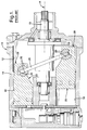
- a typical prior art compressor having swash plate driven pistons is shown in Figure 1.
- a compressor housing indicated generally at 10 has a cylindrical inner surface 12 surrounding a cylinder block 14.
- Block 14 contains a series of cylinder bores 16 arranged around a central axis A.
- a central drive shaft 18 rotates a fixed and slanted swash plate 20, the edge of which nutates axially back and forth over a defined stroke.
- Each piston, indicated generally at 22, is concurrently driven back and forth within its respective bore 16.
- Each piston 22 has a socketed notch 24 at the rear thereof that fits over the edge of swash plate 20 on a pair of half ball shoes 26 that allow the swash plate edge to both slide freely and twist through the notch 24 as the piston 22 is driven back and forth.
- a preferable anti rotation device has been a semi cylindrical wing on the back of the piston, which rides closely along the cylindrical inner surface of the compressor housing.
- the entire outer surface of the wing comprises a semi cylinder that is concentric to the inner surface of the housing.
- the two surfaces also have nearly the same radius, in addition to being concentric, then they conform so closely that very little rotation of the piston about its own axis is possible. No alteration of the already cylindrical inner surface of the compressor housing is needed.
- An example may be seen in USPN 4,963,074 to Sanuki et al, in Figure 11 at 557. Oddly enough, this particular reference describes the semi cylindrical wing 557 as having a different function, but it would certainly provide anti rotation as well.
- FIG. 2 and 3 show an anti rotation wing in which the wing's outer surface either does not lie on a single cylindrical surface, or at least does not lie on a single cylindrical surface that is concentric to the inner surface of the compressor housing.
- This basic type of anti rotation wing is shown in Figures 2 and 3, indicated generally at 28.
- the outer surface of wing 28 has a central area 30 of arbitrary, predetermined width which is flattened off, and which plays no real part in the anti rotation action, since it does not contact the housing inner surface 12.
- the central area 30 is bounded by a pair of side edges 32, parallel to each other and to the housing inner surface 12, which have a predetermined radial clearance therefrom when the piston wing 28 is in a centered condition.
- the side edges 32 are not the terminal, outermost edges of the outer surface of the wing 28. If they were, then they would contact the housing inner surface 12 directly, and would thereby create the same sharp edge wear problem noted above. Instead, a pair of side surfaces 34 (described in more detail below) are located outboard of both side edges 32, and it is one of these that contacts the housing inner surface 12, depending on the direction of piston turning. The left side surface 34 is shown making contact in Figure 3.
- FIG. 5 Another embodiment in the same patent, Figure 5, takes a different approach.
- the outer surface 25a of the anti rotation wing is a single radius semi-cylinder, but with a radius that is apparently supposed to be midway between the radii of the piston (which is smaller) and the radius of the housing inner surface (which is larger). While this is a different approach, it has literally nothing to do with why an anti-rotation wing works. It works, fundamentally, because the clearance of the wing edges from the inner surface of the housing is less than the clearance of the piston notch from the edge of the swash plate. What the shape of the wing is between the two edges is irrelevant. While that comparative clearance relation does hold for the outer surface 25a of the Figure 5 embodiment, it is incidental to why it would work to limit piston turning.
- An automotive air conditioning compressor piston in accordance with the present invention is characterised by the features specified in Claim 1.
- a typical compressor housing, piston block and shaft driven swash plate are provided.
- Each cylinder bore contains a piston which reciprocates about its own axis, parallel to the central compressor housing axis.
- a socketed notch in each piston rides over the edge of a shaft driven swash plate, supported for free sliding and twisting.
- An anti rotation wing at the back of each piston rides back and forth with the reciprocating piston, near the cylindrical inner surface of the compressor housing.
- the outer surface of the anti rotation wing has a pair of spaced side edges, parallel to each other and to the inner surface of the compressor housing, with a flattened off center area between the side edges.
- each side edge is spaced from the inner surface by a predetermined, equal radial clearance.
- the radial clearance is sufficiently small so that either side edge can make contact with the inner surface of the compressor housing well before the piston notch will made contact with the edge of the swash plate.
- each side edge is bounded by a semi cylindrical pad integral to and outboard of its respective side edge.
- Each pad has a radius of curvature basically equal to the inner surface of the compressor housing.
- each semi cylindrical pad and the compressor housing inner surface is sufficient to assure that when the anti rotation wing does rotate out of its centered position far enough for either side edge to contact the compressor housing surface, the semi cylindrical pad outboard of that side edge contacts the compressor housing inner surface as well, closely conforming thereto because of the equal radii. In the contact position, the pad's center of curvature does coincide with the central axis of the compressor housing. This close and continuous mutual contact between pad and housing inner surface assures a large area of bearing support, with consequently less wear and noise.
- Piston 40 is used in conjunction with the same compressor housing 10 with the same radius inner surface 12, cylinder block 14, bores 16, shaft 18 and swash plate 20.
- Piston 40 is the same basic size, length, material and weight as piston 22 described above, and has the same socketed notch, indicated at 24', which fits over the edge of swash plate 20.
- the back of piston 40 has an anti rotation wing, indicated generally at 42, which, in general size and location, is very similar to the anti rotation wing 28 described above.
- the operative portion of wing 42 is significantly different in shape.
- the center area 44 of the wing outer surface is basically flat, specifically a very shallow V shape, with a radial width of approximately 18 mm.
- the width of the center area 44 is fairly arbitrary, but would not be a great deal larger than the radius of the piston 40 in any particular case.
- the center area 44 is bounded by a pair of imaginary side edges 46, parallel to one another and to the housing inner surface 12.
- the side edges 46 are imaginary in the sense that they are an arbitrary dividing lines between the center area 44 and a pair of semi cylindrical pads 48 that lie outboard of the center area 44, but are important in defining the shape and operation of the pads 48, described below.
- piston 40 and wing 42 are shown in a neutral or centered position, where a radial plane bisecting the wing 42 and passing through the piston axis Pa also passes through the housing central axis A.
- the side edges 46 are a useful construct in that they establish an important neutral position radial clearance "c" from the housing inner surface 12.
- the clearance "c" is the most significant, however, in that it is the smallest radial clearance outboard of the center area 44, and will be the first "point" (line, in fact) to hit the housing inner surface 12 when the piston 40 turns in either direction.
- the clearance "c” is quite small, about .4 mm, but that will vary from case to case.
- the clearance “c” need only be chosen to be small enough to contact the housing inner surface 12 before the notch 24' hits the edge of the swash plate 20.
- the actual clearance “c” will typically be chosen to be far smaller than that fundamental upper clearance limit. This assures that the rotation limiting contact will occur along before collision with the swash plate 20, and before significant angular momentum has been acquired by the rotating piston 40.
- the clearance "c” is closed out after the wing 42 has rotated only about 4 degrees in either direction.
- the pads 48 are semi cylindrical, which, in a two dimensional drawing, is represented by two circular arcs, each subtending, in the embodiment disclosed, approximately four degrees. It bears repeating, at this point, the list of possible prior art shapes and geometrical relationships for the circular arcs that represent the pads 48, as described above. These include, one, circular arcs that are both equal in radius to, and concentric to, the housing inner surface 12. These would provide a large area of constant bearing contact, but also continual friction. Two, the circular arcs could be concentric to, but smaller in radius than, the housing inner surface 12, which leaves a radial clearance to reduce rubbing. Three, the circular arcs could be smaller in radius than, and not concentric to, the housing radius surface 12.
- the circular arcs could be larger in radius than, and not concentric to, the housing radius surface 12.
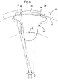
- the basic geometrical shape and theory of the cylindrical pads 48 are illustrated. Only the left pad 48 is shown, but the right pad 48 is a symmetrical, mirror image of it.
- the circular arcs that represent the pads 48 are substantially equal in radius to the housing inner surface 12, which, in the embodiment disclosed, is approximately 25.4 mm.
- the radius of housing inner surface 12 could, of course, be any value desired.
- the pads 48 are not concentric to the housing inner surface 12 central axis A. Instead, the center of the left pad 48, shown at Pc, falls to the right of A. (The center of the right pad 48 would fall equally to the left).
- the arc that represents the pad 48 therefore, falls away from the circle that represents the housing inner surface 12.
- the degree of eccentricity indicated at "e” is carefully chosen so that, when the piston wing 42 rotates clockwise far enough for the side edge 46 to close out the clearance "c", the pad 48 simultaneously contacts the housing inner surface 12. Because of the matching radius of the pad 48, it makes close, continuous contact with the housing inner surface 12 over its entire arc width, with benefits described below. To assure that the pad 48 makes this simultaneous contact, it has to be located properly relative to the side edge 46, with the right degree of eccentricity "e" of the pad center point Pc relative to the axis A.
- One way of assuring this in two dimensions is to establish a reference frame, such as the dotted vertical line drawn between the center axis Pa of the piston 40 and center axis A of housing surface 12. Then, the eccentricity "e” is resolved into components in that reference frame. As illustrated, those two components are a vertical distance ("Y") from Pa measured along the dotted vertical line and a horizontal distance ("X") from A, measured perpendicular to the dotted vertical line.
- Y vertical distance
- X horizontal distance
- the distance "e” is almost horizontal itself, and essentially coincides with the X component.
- An arc with the same radius as housing inner surface 12, and also having the center point Pc so established, will then be in the proper location in two dimensional space.
- FIG. 6 if the piston 40 and wing 42 turn far enough counterclockwise, the left hand side edge 46 and left hand pad 48 make simultaneous contact with the housing inner surface 12. "Far enough” in this case is only about four degrees, as noted above.
- the side edge 46 makes “line contact” with the housing inner surface 12 in the geometric sense only, since it is effectively integral to the pad 48.
- the pad 48 makes close contact with the housing inner surface 12 over its entire arc width, not just along a sharp edge or narrow ridge. This larger load bearing contact area reduces wear and noise, and is similar if effect to the complete contact provided by the old, completely conforming anti rotation wing.
- the wing 42 need not be at the very rear of piston 40, but could, for example, sit directly over the notch 24'.
- a pad 48 on only one side of wing 42 could be used, if most of the contact were expected only on that one side. Or, the arc width of the pad 48 could be made greater on the side where most of the contact was expected. While each pad should have the same radius and same basic location relative to the axis A, there is no requirement that they have the same arc width or radial width.
- the center points Pc of the pads 48 are established, as noted above, they are simple to machine, being simple semi cylinders, and could be cast or forged to near net shaped before machining. Again, the center area 44 could be any shape, or even cut out completely, so that the pads 48 would be defined entirely by the side edges 46 and the circular arcs as described. Therefore, it will be understood that it is not intended to limit the invention to just the embodiment disclosed.
Landscapes
- Engineering & Computer Science (AREA)
- Manufacturing & Machinery (AREA)
- Mechanical Engineering (AREA)
- General Engineering & Computer Science (AREA)
- Compressors, Vaccum Pumps And Other Relevant Systems (AREA)
- Compressor (AREA)
Applications Claiming Priority (2)
| Application Number | Priority Date | Filing Date | Title |
|---|---|---|---|
| US08/755,750 US5720215A (en) | 1996-11-25 | 1996-11-25 | Automotive air conditioning compressor piston with eccentric anti rotation pad |
| US755750 | 1996-11-25 |
Publications (3)
| Publication Number | Publication Date |
|---|---|
| EP0844391A2 true EP0844391A2 (de) | 1998-05-27 |
| EP0844391A3 EP0844391A3 (de) | 2000-10-25 |
| EP0844391B1 EP0844391B1 (de) | 2004-01-14 |
Family
ID=25040496
Family Applications (1)
| Application Number | Title | Priority Date | Filing Date |
|---|---|---|---|
| EP97203287A Expired - Lifetime EP0844391B1 (de) | 1996-11-25 | 1997-10-23 | Kompressor einer Fahrzeugklimaanlage mit einer Antirotationseinrichtung für die Kompressorkolben |
Country Status (3)
| Country | Link |
|---|---|
| US (1) | US5720215A (de) |
| EP (1) | EP0844391B1 (de) |
| DE (1) | DE69727194T2 (de) |
Families Citing this family (9)
| Publication number | Priority date | Publication date | Assignee | Title |
|---|---|---|---|---|
| JPH09268975A (ja) * | 1996-04-03 | 1997-10-14 | Sanden Corp | 斜板式圧縮機におけるピストン回動規制構造 |
| USD417225S (en) | 1996-06-13 | 1999-11-30 | Kabushiki Kaisha Toyoda Jidoshokki Seisakusho | Compressor piston |
| DE69732325T3 (de) * | 1996-07-15 | 2008-12-04 | Kabushiki Kaisha Toyota Jidoshokki, Kariya | Kolben für Kolbenkompressoren |
| US6006652A (en) * | 1998-10-30 | 1999-12-28 | General Motors Corporation | Automotive refrigerant wobble plate type compressor piston with improved ball and socket joint |
| US6325599B1 (en) * | 2000-04-04 | 2001-12-04 | Visteon Global Technologies, Inc. | Piston having anti-rotation for swashplate compressor |
| EP1167758B1 (de) * | 2000-06-27 | 2003-09-24 | Halla Climate Control Corp. | Kolbendrehschutzstruktur für einen verstellbaren Taumelscheibenverdichter |
| US6786703B2 (en) | 2001-11-02 | 2004-09-07 | Delphi Technologies, Inc. | Variable capacity air conditioning compressor with improved crankcase oil retention |
| DE60229915D1 (de) * | 2002-01-17 | 2009-01-02 | Zexel Valeo Climate Contr Corp | Schief- oder Taumelscheibenverdichter |
| JP2008248895A (ja) * | 2008-06-20 | 2008-10-16 | Sanden Corp | 斜板式圧縮機のピストン構造 |
Family Cites Families (9)
| Publication number | Priority date | Publication date | Assignee | Title |
|---|---|---|---|---|
| JPS62133973A (ja) * | 1985-12-05 | 1987-06-17 | 松下電器産業株式会社 | 処置装置 |
| US4963074A (en) * | 1988-01-08 | 1990-10-16 | Nippondenso Co., Ltd. | Variable displacement swash-plate type compressor |
| JPH0449676A (ja) * | 1990-06-18 | 1992-02-19 | Sharp Corp | 半導体可視光センサ |
| JPH06109874A (ja) * | 1992-09-24 | 1994-04-22 | Yuhshin Co Ltd | 時計時刻設定用の音声認識装置 |
| JP3125518B2 (ja) * | 1993-06-04 | 2001-01-22 | 株式会社豊田自動織機製作所 | 斜板式圧縮機におけるピストン回動規制構造 |
| JPH08109874A (ja) * | 1994-10-11 | 1996-04-30 | Calsonic Corp | 斜板式コンプレッサ |
| DE69609118T2 (de) * | 1995-04-13 | 2000-11-16 | Calsonic Corp., Tokio/Tokyo | Schiefscheibenverdichter mit veränderlicher Verdrängung |
| JPH09268975A (ja) * | 1996-04-03 | 1997-10-14 | Sanden Corp | 斜板式圧縮機におけるピストン回動規制構造 |
| DE69732325T3 (de) * | 1996-07-15 | 2008-12-04 | Kabushiki Kaisha Toyota Jidoshokki, Kariya | Kolben für Kolbenkompressoren |
-
1996
- 1996-11-25 US US08/755,750 patent/US5720215A/en not_active Expired - Lifetime
-
1997
- 1997-10-23 DE DE69727194T patent/DE69727194T2/de not_active Expired - Lifetime
- 1997-10-23 EP EP97203287A patent/EP0844391B1/de not_active Expired - Lifetime
Also Published As
| Publication number | Publication date |
|---|---|
| EP0844391B1 (de) | 2004-01-14 |
| DE69727194D1 (de) | 2004-02-19 |
| EP0844391A3 (de) | 2000-10-25 |
| US5720215A (en) | 1998-02-24 |
| DE69727194T2 (de) | 2004-06-09 |
Similar Documents
| Publication | Publication Date | Title |
|---|---|---|
| US6139283A (en) | Variable capacity swash plate type compressor | |
| EP0216612B1 (de) | Schiefscheibenverdichter | |
| JP3695724B2 (ja) | 斜板式コンプレッサの片頭式ピストンの製造方法 | |
| EP0844391B1 (de) | Kompressor einer Fahrzeugklimaanlage mit einer Antirotationseinrichtung für die Kompressorkolben | |
| JP3042650B2 (ja) | 斜板式圧縮機 | |
| US5934172A (en) | Swash plate type compressor having an improved piston rotation regulating-structure | |
| KR100282042B1 (ko) | 가변용량 사판식 압축기 | |
| JPH08109874A (ja) | 斜板式コンプレッサ | |
| KR100717329B1 (ko) | 피스톤 회전 방지 구조물을 갖는 가변 용적형 압축기 | |
| JP3566125B2 (ja) | 斜板式圧縮機 | |
| US5477773A (en) | Wave plate type compressor | |
| JPH10213064A (ja) | 可変容量型斜板式圧縮機 | |
| JP2000320455A (ja) | 斜板式圧縮機及びラジアル転がり軸受け | |
| JP3060679B2 (ja) | 揺動斜板式可変容量圧縮機 | |
| EP1001168A2 (de) | Kolben für Taumelscheibenkompressor | |
| EP1111236A2 (de) | Taumelscheibenverdichter veränderlicher Verdrängung mit Leitstift | |
| JPH087098Y2 (ja) | 容量可変斜板式コンプレッサ | |
| JP3155858B2 (ja) | 斜板式圧縮機 | |
| JPH0979137A (ja) | 斜板式コンプレッサ | |
| JPH06346839A (ja) | ピストン式圧縮機 | |
| JP2590366Y2 (ja) | 斜板式圧縮機 | |
| JPH07310652A (ja) | 可変容量型斜板式圧縮機 | |
| KR200156660Y1 (ko) | 압축기 | |
| JP2003028058A (ja) | 可変容量斜板式圧縮機の駆動軸支持用スラストベアリング支持構造 | |
| JPH02275070A (ja) | 斜板式圧縮機 |
Legal Events
| Date | Code | Title | Description |
|---|---|---|---|
| PUAI | Public reference made under article 153(3) epc to a published international application that has entered the european phase |
Free format text: ORIGINAL CODE: 0009012 |
|
| AK | Designated contracting states |
Kind code of ref document: A2 Designated state(s): DE FR GB |
|
| AX | Request for extension of the european patent |
Free format text: AL;LT;LV;RO;SI |
|
| PUAL | Search report despatched |
Free format text: ORIGINAL CODE: 0009013 |
|
| AK | Designated contracting states |
Kind code of ref document: A3 Designated state(s): AT BE CH DE DK ES FI FR GB GR IE IT LI LU MC NL PT SE |
|
| AX | Request for extension of the european patent |
Free format text: AL;LT;LV;RO;SI |
|
| RIC1 | Information provided on ipc code assigned before grant |
Free format text: 7F 04B 27/10 A, 7F 04B 39/00 B, 7F 04B 27/08 B |
|
| RAP1 | Party data changed (applicant data changed or rights of an application transferred) |
Owner name: DELPHI TECHNOLOGIES, INC. |
|
| 17P | Request for examination filed |
Effective date: 20010425 |
|
| AKX | Designation fees paid |
Free format text: DE FR GB |
|
| GRAH | Despatch of communication of intention to grant a patent |
Free format text: ORIGINAL CODE: EPIDOS IGRA |
|
| GRAS | Grant fee paid |
Free format text: ORIGINAL CODE: EPIDOSNIGR3 |
|
| GRAA | (expected) grant |
Free format text: ORIGINAL CODE: 0009210 |
|
| AK | Designated contracting states |
Kind code of ref document: B1 Designated state(s): DE FR GB |
|
| REG | Reference to a national code |
Ref country code: GB Ref legal event code: FG4D |
|
| REF | Corresponds to: |
Ref document number: 69727194 Country of ref document: DE Date of ref document: 20040219 Kind code of ref document: P |
|
| ET | Fr: translation filed | ||
| PLBE | No opposition filed within time limit |
Free format text: ORIGINAL CODE: 0009261 |
|
| STAA | Information on the status of an ep patent application or granted ep patent |
Free format text: STATUS: NO OPPOSITION FILED WITHIN TIME LIMIT |
|
| 26N | No opposition filed |
Effective date: 20041015 |
|
| REG | Reference to a national code |
Ref country code: DE Ref legal event code: R082 Ref document number: 69727194 Country of ref document: DE Representative=s name: BRP RENAUD UND PARTNER MBB RECHTSANWAELTE PATE, DE Ref country code: DE Ref legal event code: R082 Ref document number: 69727194 Country of ref document: DE Representative=s name: BRP RENAUD UND PARTNER MBB, DE Ref country code: DE Ref legal event code: R081 Ref document number: 69727194 Country of ref document: DE Owner name: MAHLE INTERNATIONAL GMBH, DE Free format text: FORMER OWNER: DELPHI TECHNOLOGIES, INC., TROY, MICH., US |
|
| REG | Reference to a national code |
Ref country code: FR Ref legal event code: PLFP Year of fee payment: 19 |
|
| REG | Reference to a national code |
Ref country code: FR Ref legal event code: PLFP Year of fee payment: 20 |
|
| REG | Reference to a national code |
Ref country code: GB Ref legal event code: 732E Free format text: REGISTERED BETWEEN 20161208 AND 20161214 |
|
| PGFP | Annual fee paid to national office [announced via postgrant information from national office to epo] |
Ref country code: GB Payment date: 20161028 Year of fee payment: 20 Ref country code: FR Payment date: 20161027 Year of fee payment: 20 |
|
| PGFP | Annual fee paid to national office [announced via postgrant information from national office to epo] |
Ref country code: DE Payment date: 20170102 Year of fee payment: 20 |
|
| REG | Reference to a national code |
Ref country code: DE Ref legal event code: R071 Ref document number: 69727194 Country of ref document: DE |
|
| REG | Reference to a national code |
Ref country code: GB Ref legal event code: PE20 Expiry date: 20171022 |
|
| REG | Reference to a national code |
Ref country code: FR Ref legal event code: TP Owner name: MAHLE INTERNATIONAL GMBH, DE Effective date: 20180103 |
|
| PG25 | Lapsed in a contracting state [announced via postgrant information from national office to epo] |
Ref country code: GB Free format text: LAPSE BECAUSE OF EXPIRATION OF PROTECTION Effective date: 20171022 |