EP0845406B1 - Sattelkupplung - Google Patents
Sattelkupplung Download PDFInfo
- Publication number
- EP0845406B1 EP0845406B1 EP97204052A EP97204052A EP0845406B1 EP 0845406 B1 EP0845406 B1 EP 0845406B1 EP 97204052 A EP97204052 A EP 97204052A EP 97204052 A EP97204052 A EP 97204052A EP 0845406 B1 EP0845406 B1 EP 0845406B1
- Authority
- EP
- European Patent Office
- Prior art keywords
- plate
- hitch
- pads
- lubricious
- underlayer
- Prior art date
- Legal status (The legal status is an assumption and is not a legal conclusion. Google has not performed a legal analysis and makes no representation as to the accuracy of the status listed.)
- Expired - Lifetime
Links
Images

Classifications
-
- B—PERFORMING OPERATIONS; TRANSPORTING
- B62—LAND VEHICLES FOR TRAVELLING OTHERWISE THAN ON RAILS
- B62D—MOTOR VEHICLES; TRAILERS
- B62D53/00—Tractor-trailer combinations; Road trains
- B62D53/04—Tractor-trailer combinations; Road trains comprising a vehicle carrying an essential part of the other vehicle's load by having supporting means for the front or rear part of the other vehicle
- B62D53/08—Fifth wheel traction couplings
- B62D53/0885—Comprising devices to limit or to compensate for wear or excessive play; Lubricating, shock absorbing, bearing devices, or the like
Definitions
- This invention relates to a hitch assembly having lubricious parts and particularly to a fifth wheel hitch assembly.
- a common hitch for hauling large trailers is the well-known fifth wheel hitch which has a large bifurcated bearing plate that receives a kingpin and locks it in place with one or more jaws.
- the kingpin is mounted on a trailer which also has a bearing plate which rests upon and pivots on the hitch upper surface, to enable articulation between the trailer and its towing tractor.
- This pivotal action is typically aided by a layer of grease on the hitch surface. Because this grease is not only messy but also tends to retain dirt and dust which cause wear, it is undesirable.
- US 5,165,714 discusses a tractor fifth wheel with bearing plate lubricating liner comprising a fifth wheel bearing plate which receives a single wear liner.
- the wear liner is attached to the bearing plate by a countersunk bolt.
- the invention provides a fifth wheel hitch having specially configurated, interfitting lubricious pads mounted onto the hitch plate covering substantially all of the bearing surface, yet arranged to enable each pad to perform independently to a degree allowing localized "stick-slip" motion between that lubricious pad and the overlying trailer bearing plate.
- Lubricious polymer layer segments to form replaceable segmental pads are bonded to like configurated segmental steel backing plates. Threaded studs are stud-welded to the backing plates, projecting only from the bottom thereof, the studs extending down through orifices in the hitch plate for securement to the hitch plate by nuts.
- the segmental, interfitting pads are in groups of three or six, with lateral pads being in mirror image arrangement and a cooperative, overlapping forward pad or pair of mirror-image forward pads, the latter having a stem portion that extends between the lateral pads, and having a forward cross portion that overlaps the lateral pads.
- the interfitting group of individual pads is retained within and protrudes above a peripheral upstanding rim.
- Each pad is able to transfer torsional loading to an adjacent pad and then to the peripheral rim, for cooperative mutual support, yet allowing independent surface-to-surface action between each pad and the trailer bearing plate.
- the peripheral rim provides support structure to support the concentrated load, preventing significant crushing of the lubricious pad element.
- the upper surface of the novel structure is free of exposed fasteners which could cause dirt accumulation, corrosion, reduction of pad strength and reduction of maximum useful bearing surface area.
- the individual pads can be selectively removed and replaced.
- a minimum of molds is needed to form the polymeric pad elements.
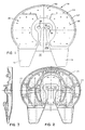
- the fifth wheel hitch assembly 10 depicted in Figs. 1-9 comprises a fifth wheel hitch plate 12 having a bifurcated rear portion which forms laterally spaced ramps 14 astraddle a kingpin receiving mouth 16 and throat 18.
- a pair of jaws such as those shown in U.S. Patent 4,428,595 are mounted in the known manner on pivot pins 20 to pivot thereon and lock a conventional depending kingpin (not shown) on a trailer within throat 18 until purposely released.
- This hitch has an upstanding peripheral rim 12' extending around both sides and the forward end of the hitch, defining a pocket 12" (Fig. 4) in the top of the hitch plate.
- a lower, transverse, reinforcing beam 20a extends across the mouth 16 below the level of the entering kingpin, in conventional fashion.
- the opposite sides of plate 12 are mounted on bearing trunnions 22 in conventional fashion, to pivot forwardly and rearwardly on a transverse pivot axis.
- Hitch plate 12 has an overall pattern of orifices 24 (Fig. 2) extending through the thickness of the plate.
- Fig. 1 to be mounted on hitch plate 12 are specially configurated, interfitting and cooperative lubricious pad subassemblies, with a pair of them 30 being on opposite lateral sides of the mouth and throat of the plate, and the third one 32 being a forward, generally T-shaped lubricious pad subassembly.
- the two pads 30 are basically in mirror-image relationship, having the same arcuate curvilinear configuration which arcs around the mouth and throat area and radially extends to the outer edge of pocket 12", i.e., out to rim 12'.
- the T-shaped pad subassembly 32 has lateral portions which overlap pad subassemblies 30 to form the cross member of the T, and a second portion protruding rearwardly between them to form the stem of the T, in a generally T-shaped configuration.
- Each of the pad subassemblies 30 depicted includes a steel underplate 40 having an upper surface and a lower surface. Bonded to the upper surface of steel plate 40 is a lubricious layer 42, the lower surface of which is below the level of peripheral rim 12'. Steel plate 40 is preferably of a rolled steel of a thickness within the range of about 0.762mm to 3.18mm (0.030 to 0.125 inch). A plurality of threaded studs 44 are stud-welded at their upper ends to the bottom surface of plate 40.
- These studs are arc welded in position in a pattern on the individual pads corresponding to portions of the overall pattern of orifices 24 in plate 12, to enable the studs to project down through the hitch plate for securement by a washer 46 and nut 48 on each stud.
- Lubricious layer 42 is of sufficient thickness to project above peripheral rim 12', i.e., have its upper bearing surface above the rim. Its upper surface is nonperforate.
- the layer may be any of several lubricious materials, typically containing or comprising a polymeric material, preferably nylon reinforced with embedded glass fibers or polytetrafluoroethylene embodied in a sintered matrix.
- the lubricious layer may be molded onto the underplate to be bonded in situ, or applied as a prefabricated layer and bonded to the underplate as by an adhesive.
- the lubricious layers require only two mold configurations to form them since the layers for lateral pads 30 are simply the inverted form of each other.
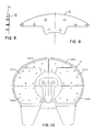
- the stud pattern there depicted represents either the bottom side of the left-hand underplate, or broken line locations of the stud pattern viewing the top side of the right-hand underplate.
- Fig. 8 represents the stud pattern when considered from the bottom of the underplate, or in broken line locations viewing the top of the underplate.
- Fig. 10 is depicted an alternative embodiment which employs six pad subassemblies rather than three as in the earlier embodiment.
- the fifth wheel plate 12 is the same as that previously described relative to the embodiment in Fig. 1.
- the pads are configurated in the same overall assembly pattern as previously shown and described, the stud pattern preferably being comparable and the orifice pattern in hitch plate 12 being the same as in the first embodiment. In this instance, however, instead of individual pad subassemblies 30 and 32, there are three pairs of mirror image twin pads 130a and 130b, 131a, 131b, and 132a and 132b.
- mounting of the interfitting pad subassemblies is simple, namely placing the two layer pads in position with the studs extending down through the openings and fastening the nuts in position to retain them on the hitch plate.
- Replacement of the pads, either individually or collectively, is also easy to accomplish by removing nuts 48 from studs 44, lifting any worn pad subassemblies from the hitch plate, and replacing them with new ones.
- each pad is able to perform independently in the surface-to-surface relationship with the overlying trailer bearing plate to a degree enabling localized "stick-slip" motion characteristics of friction relationship between the polymer of the pad surface and the metal of the overlying trailer bearing plate.
Landscapes
- Engineering & Computer Science (AREA)
- Chemical & Material Sciences (AREA)
- Combustion & Propulsion (AREA)
- Transportation (AREA)
- Mechanical Engineering (AREA)
- Connection Of Plates (AREA)
- Toys (AREA)
- General Details Of Gearings (AREA)
- Body Structure For Vehicles (AREA)
- Mirrors, Picture Frames, Photograph Stands, And Related Fastening Devices (AREA)
- Mechanical Operated Clutches (AREA)
- Pivots And Pivotal Connections (AREA)
Claims (3)
- Sattelkupplung (10) mit einer Sattelkupplungsplatte (12), die einen gegabelten hinteren Bereich mit einer Aufnahme (16) für einen Zugsattelzapfen, Maul (18) und Raste und eine obere Oberfläche aufweist, dadurch gekennzeichnet, daß mehrere Schmierpolster (30, 32) auf der oberen Obertläche der Sattelkupplungsplatte angeordnet sind, die eine Lagerfläche auf der Sattelkupplungsplatte bilden, wobei jedes Polster eine Unterlageplatte (40) mit einer unteren Oberfläche auf der Sattelkupplungsplatte und einer oberen Oberfläche und eine Schmierauflage (42) aufweist, die mit der oberen Oberfläche der Unterlageplatte verbunden ist, wobei die Schmierauflagen der Polster die Lagerfläche bilden; und daß mehrere die Unterlageplatte und die Sattelkupplungsplatte verbindende Befestigungselemente (46, 48) angeordnet sind, die als Gewindebolzen mit an der unteren Oberfläche der Unterlageplatte verschweißten oberen Enden ausgebildet sind.
- Sattelkupplung (10) nach Anspruch 1, dadurch gekennzeichnet, daß die Schmierauflage (42) der Polster unperforiert ist.
- Sattelkupplung (10) nach Anspruch 1, dadurch gekennzeichnet, daß die Unterlageplatte (40) aus Stahl besteht; wobei die Sattelkupplungsplatte (12) eine Anordnung von mehreren durch sie hindurchgehender, vertikaler, die Befestigungselemente aufnehmender Öffnungen aufweist; wobei die oberen Enden der Bolzen (44) sich nach unten von der unteren Oberfläche der stählernen Unterlage erstrecken, korrespondierend zu der Anordnung der Öffnungen in der Sattelkupplungsplatte angeordnet sind und untere, sich durch die Öffnungen abwärts erstreckende Enden aufweisen; und wobei mehrere Befestigungselemente (46, 48) an den unteren Enden der Bolzen für die Befestigung der Polster an der Sattelkupplungsplatte vorgesehen sind; wobei die Befestigungselemente Gewindemuttern (48) sind.
Applications Claiming Priority (3)
| Application Number | Priority Date | Filing Date | Title |
|---|---|---|---|
| US314410 | 1994-09-28 | ||
| US08/314,410 US5522613A (en) | 1994-09-28 | 1994-09-28 | Self lubicating fifth wheel hitch |
| EP95306234A EP0704369B1 (de) | 1994-09-28 | 1995-09-06 | Sattelkupplung |
Related Parent Applications (1)
| Application Number | Title | Priority Date | Filing Date |
|---|---|---|---|
| EP95306234A Division EP0704369B1 (de) | 1994-09-28 | 1995-09-06 | Sattelkupplung |
Publications (3)
| Publication Number | Publication Date |
|---|---|
| EP0845406A2 EP0845406A2 (de) | 1998-06-03 |
| EP0845406A3 EP0845406A3 (de) | 2000-05-03 |
| EP0845406B1 true EP0845406B1 (de) | 2001-12-12 |
Family
ID=23219851
Family Applications (2)
| Application Number | Title | Priority Date | Filing Date |
|---|---|---|---|
| EP95306234A Expired - Lifetime EP0704369B1 (de) | 1994-09-28 | 1995-09-06 | Sattelkupplung |
| EP97204052A Expired - Lifetime EP0845406B1 (de) | 1994-09-28 | 1995-09-06 | Sattelkupplung |
Family Applications Before (1)
| Application Number | Title | Priority Date | Filing Date |
|---|---|---|---|
| EP95306234A Expired - Lifetime EP0704369B1 (de) | 1994-09-28 | 1995-09-06 | Sattelkupplung |
Country Status (8)
| Country | Link |
|---|---|
| US (1) | US5522613A (de) |
| EP (2) | EP0704369B1 (de) |
| JP (1) | JP3047315B2 (de) |
| CN (1) | CN1123235A (de) |
| AU (1) | AU686417B2 (de) |
| CA (1) | CA2156884C (de) |
| DE (2) | DE69524637T2 (de) |
| NZ (1) | NZ272822A (de) |
Families Citing this family (17)
| Publication number | Priority date | Publication date | Assignee | Title |
|---|---|---|---|---|
| US5746438A (en) * | 1995-03-03 | 1998-05-05 | Jost--Werke AG | Fifth wheel |
| DE19609314A1 (de) * | 1996-03-09 | 1997-09-11 | Ruefas Pagid Ag | Sattelkupplung |
| US5865458A (en) * | 1996-12-20 | 1999-02-02 | Amsted Industries Incorporated | Reduced weight fifth wheel assembly |
| ES1037216Y (es) * | 1997-05-09 | 1999-04-16 | Vega Diez Miguel Angel | Placa autolubricante para la quinta rueda de vehiculos industriales. |
| US6010141A (en) * | 1997-08-06 | 2000-01-04 | Global Polymer Industries, Inc. | Molded bearing plate assembly |
| DE19813635A1 (de) * | 1998-03-27 | 1999-09-30 | Jost Werke Ag | Sattelkupplung |
| US6098754A (en) * | 1999-01-27 | 2000-08-08 | Toner; Mark E. | Pneumatic greasing system for a fifth wheel |
| US20010028160A1 (en) | 1999-02-26 | 2001-10-11 | Athans George C. | Self-lubricating trailer bearing plate for fifth wheel |
| CN100400361C (zh) * | 2001-04-25 | 2008-07-09 | 霍兰集团公司 | 具有多孔支撑部件的牵引座润滑板 |
| ATE457920T1 (de) * | 2002-11-08 | 2010-03-15 | Saf Holland Inc | Leichte sattelkupplungsanordnung |
| NL1026217C2 (nl) * | 2004-05-18 | 2005-11-21 | Herman Karel Kerklingh | Trekker/oplegger-combinatie. |
| DE102008006203B4 (de) * | 2008-01-26 | 2011-03-17 | Jost-Werke Gmbh | Fahrzeugkupplung zum Herstellen einer mechanischen Verbindung zwischen einem ersten und einem zweiten Fahrzeug |
| DE102008006204B4 (de) * | 2008-01-26 | 2011-03-17 | Jost-Werke Gmbh | Fahrzeugkupplung |
| DE102011109576A1 (de) * | 2011-08-03 | 2013-02-07 | Pilz Gmbh & Co. Kg | Bedienterminal |
| US9238390B2 (en) * | 2012-07-03 | 2016-01-19 | Rel, Inc. | Composite articles, wear plates and methods |
| US20150084310A1 (en) * | 2013-09-24 | 2015-03-26 | Roger Dale Price | Universal fifth wheel plate cover and method |
| DE102021134549A1 (de) * | 2021-12-23 | 2023-06-29 | Jost-Werke Deutschland Gmbh | Sattelkupplungsplatte und Sattelkupplung |
Family Cites Families (29)
| Publication number | Priority date | Publication date | Assignee | Title |
|---|---|---|---|---|
| US2508610A (en) * | 1946-10-19 | 1950-05-23 | George A Kendall | Trailer fifth wheel |
| DE1228940B (de) * | 1962-04-27 | 1966-11-17 | Fischer Ag Georg | Gleitverbindung einer Sattelschlepperkupplung mit Kupplungsplatte und Aufliegerplatte |
| US3174812A (en) * | 1962-04-27 | 1965-03-23 | Fischer Ag Georg | Fifth wheel construction |
| US3257969A (en) * | 1962-04-30 | 1966-06-28 | Lord Corp | Railway car center plate |
| US3275390A (en) * | 1964-09-01 | 1966-09-27 | Phillips Petroleum Co | Retainer ring and washer for tractor-trailer with fifth wheel |
| US3337277A (en) * | 1965-10-23 | 1967-08-22 | Koppers Co Inc | Fifth wheel coupling for land vehicles |
| US3451731A (en) * | 1967-03-09 | 1969-06-24 | Apex Bearings Co The | Thrust bearing |
| US3511523A (en) * | 1968-06-21 | 1970-05-12 | Leslie T Fuller | Semi-enclosing seal means for fifth wheel |
| US3704924A (en) * | 1971-03-12 | 1972-12-05 | Randy W Lowry | Removable wear plate for fifth wheel |
| US3887251A (en) * | 1974-08-06 | 1975-06-03 | Roy H Mckay | Tractor and trailer fifth wheel bearing attachment |
| US3924909A (en) * | 1975-01-20 | 1975-12-09 | Amsted Ind Inc | Fifth wheel |
| US4045854A (en) * | 1976-06-24 | 1977-09-06 | Phillips Petroleum Company | Device for installation of plastic fifth wheel liner on a truck trailer |
| US4121853A (en) * | 1977-06-22 | 1978-10-24 | Mckay Roy H | Fifth wheel bearing attachment |
| US4169635A (en) * | 1978-02-17 | 1979-10-02 | Eastern Tool & Machine, Inc. | Fifth wheel bearing plate cover |
| US4738494A (en) * | 1982-02-16 | 1988-04-19 | Deere & Company | Wear plate for idler slide mounting |
| US4428595A (en) | 1982-03-01 | 1984-01-31 | Holland Hitch Company | Fifth wheel hitch |
| US4457531A (en) * | 1982-08-31 | 1984-07-03 | Huenger Walter | Trailer coupling |
| CA1194515A (en) * | 1983-02-28 | 1985-10-01 | Andre St. Louis | Tractor fifth wheel bearing attachment |
| FR2584670B1 (fr) * | 1985-07-15 | 1989-12-29 | Mamery Gaby | Dispositif autolubrifiant pour attelage d'engins semi-remorques |
| CH667055A5 (de) * | 1985-08-16 | 1988-09-15 | Fischer Ag Georg | Sattelkupplung mit einer kupplungsplatte. |
| DE3530467A1 (de) | 1985-08-27 | 1987-03-05 | Walter Hunger | Sattelkupplung |
| US4752081A (en) * | 1987-08-31 | 1988-06-21 | Reeners Donald G | Fifth wheel bearing plate cover with inboard protective skip plates |
| US4913263A (en) * | 1988-10-31 | 1990-04-03 | Spiers Dennis D | Grease packet for fifth wheels |
| US5066035A (en) * | 1990-04-18 | 1991-11-19 | Leonidas Athans | Trailer bearing plate for fifth wheel |
| US5165714A (en) * | 1991-03-08 | 1992-11-24 | Amsted Industries Incorporated | Tractor fifth wheel with bearing plate lubricating liner |
| US5165713A (en) * | 1991-07-03 | 1992-11-24 | 5Th Boot Industries Inc. | Fifth wheel cover |
| US5207444A (en) * | 1991-08-23 | 1993-05-04 | Tydeman Robert E | Turntable for steerable trailers |
| CA2066331C (en) * | 1992-04-16 | 1995-05-30 | Stewart Huehn | Composite fifth wheel bearing plate |
| US5431424A (en) * | 1994-04-07 | 1995-07-11 | Colwell; J. Bruce | Fifth wheel slip plate |
-
1994
- 1994-09-28 US US08/314,410 patent/US5522613A/en not_active Expired - Lifetime
-
1995
- 1995-08-21 NZ NZ272822A patent/NZ272822A/en not_active IP Right Cessation
- 1995-08-24 AU AU30239/95A patent/AU686417B2/en not_active Expired
- 1995-08-24 CA CA002156884A patent/CA2156884C/en not_active Expired - Lifetime
- 1995-09-06 DE DE69524637T patent/DE69524637T2/de not_active Expired - Fee Related
- 1995-09-06 DE DE69515775T patent/DE69515775T2/de not_active Expired - Fee Related
- 1995-09-06 EP EP95306234A patent/EP0704369B1/de not_active Expired - Lifetime
- 1995-09-06 EP EP97204052A patent/EP0845406B1/de not_active Expired - Lifetime
- 1995-09-08 CN CN95116247.0A patent/CN1123235A/zh active Pending
- 1995-09-25 JP JP7269028A patent/JP3047315B2/ja not_active Expired - Fee Related
Also Published As
| Publication number | Publication date |
|---|---|
| CN1123235A (zh) | 1996-05-29 |
| AU686417B2 (en) | 1998-02-05 |
| EP0704369A1 (de) | 1996-04-03 |
| US5522613A (en) | 1996-06-04 |
| DE69515775D1 (de) | 2000-04-27 |
| JPH08332978A (ja) | 1996-12-17 |
| EP0704369B1 (de) | 2000-03-22 |
| EP0845406A2 (de) | 1998-06-03 |
| CA2156884C (en) | 1999-11-09 |
| JP3047315B2 (ja) | 2000-05-29 |
| DE69524637D1 (de) | 2002-01-24 |
| EP0845406A3 (de) | 2000-05-03 |
| DE69515775T2 (de) | 2000-07-13 |
| AU3023995A (en) | 1996-04-18 |
| CA2156884A1 (en) | 1996-03-29 |
| NZ272822A (en) | 1997-05-26 |
| DE69524637T2 (de) | 2002-05-08 |
Similar Documents
| Publication | Publication Date | Title |
|---|---|---|
| EP0704369B1 (de) | Sattelkupplung | |
| US7879273B2 (en) | Fifth wheel lube plate having a perforated support member | |
| TWI271344B (en) | Elastic track shoe | |
| US5746438A (en) | Fifth wheel | |
| US4805926A (en) | Self-lubricating device for coupling semitrailers | |
| US3937530A (en) | Reversible track link with clamped-on shoe | |
| AU711267B2 (en) | Self lubricating fifth wheel hitch | |
| EP1283152A1 (de) | Gummi gleiskette | |
| JP3027129B2 (ja) | 弾性パッド | |
| CA1227824A (en) | Track link adhesion pad assembly | |
| JPH05278646A (ja) | ゴムパッド付き履帯 | |
| JP2595443Y2 (ja) | 無限軌道帯用履板 | |
| CA2104343C (en) | Fifth wheel slip plate | |
| JP2606785Y2 (ja) | 無限軌道帯用弾性履板 | |
| JP4071851B2 (ja) | クロ−ラ用弾性シュ− | |
| JPS6222835B2 (de) | ||
| JPH08282558A (ja) | クローラ走行装置 | |
| JPH082456A (ja) | 金属製クローラの履板用弾性パッド | |
| JPH0156022B2 (de) | ||
| JPH1067351A (ja) | ゴムシュ− | |
| JP2003095157A (ja) | 弾性体履板 | |
| JPH0730187U (ja) | 無限軌道帯用弾性履板 | |
| JPH0635089U (ja) | 鉄クローラ用ゴム履板 |
Legal Events
| Date | Code | Title | Description |
|---|---|---|---|
| PUAI | Public reference made under article 153(3) epc to a published international application that has entered the european phase |
Free format text: ORIGINAL CODE: 0009012 |
|
| AC | Divisional application: reference to earlier application |
Ref document number: 704369 Country of ref document: EP |
|
| AK | Designated contracting states |
Kind code of ref document: A2 Designated state(s): DE FR GB IT NL SE |
|
| RHK1 | Main classification (correction) |
Ipc: B62D 53/08 |
|
| PUAL | Search report despatched |
Free format text: ORIGINAL CODE: 0009013 |
|
| AK | Designated contracting states |
Kind code of ref document: A3 Designated state(s): DE FR GB IT NL SE |
|
| 17P | Request for examination filed |
Effective date: 20000814 |
|
| 17Q | First examination report despatched |
Effective date: 20001129 |
|
| GRAG | Despatch of communication of intention to grant |
Free format text: ORIGINAL CODE: EPIDOS AGRA |
|
| GRAG | Despatch of communication of intention to grant |
Free format text: ORIGINAL CODE: EPIDOS AGRA |
|
| GRAH | Despatch of communication of intention to grant a patent |
Free format text: ORIGINAL CODE: EPIDOS IGRA |
|
| GRAH | Despatch of communication of intention to grant a patent |
Free format text: ORIGINAL CODE: EPIDOS IGRA |
|
| GRAA | (expected) grant |
Free format text: ORIGINAL CODE: 0009210 |
|
| AC | Divisional application: reference to earlier application |
Ref document number: 704369 Country of ref document: EP |
|
| AK | Designated contracting states |
Kind code of ref document: B1 Designated state(s): DE FR GB IT NL SE |
|
| PG25 | Lapsed in a contracting state [announced via postgrant information from national office to epo] |
Ref country code: NL Free format text: LAPSE BECAUSE OF FAILURE TO SUBMIT A TRANSLATION OF THE DESCRIPTION OR TO PAY THE FEE WITHIN THE PRESCRIBED TIME-LIMIT Effective date: 20011212 |
|
| REG | Reference to a national code |
Ref country code: GB Ref legal event code: IF02 |
|
| REF | Corresponds to: |
Ref document number: 69524637 Country of ref document: DE Date of ref document: 20020124 |
|
| PG25 | Lapsed in a contracting state [announced via postgrant information from national office to epo] |
Ref country code: SE Free format text: LAPSE BECAUSE OF FAILURE TO SUBMIT A TRANSLATION OF THE DESCRIPTION OR TO PAY THE FEE WITHIN THE PRESCRIBED TIME-LIMIT Effective date: 20020312 |
|
| ET | Fr: translation filed | ||
| NLV1 | Nl: lapsed or annulled due to failure to fulfill the requirements of art. 29p and 29m of the patents act | ||
| PLBE | No opposition filed within time limit |
Free format text: ORIGINAL CODE: 0009261 |
|
| STAA | Information on the status of an ep patent application or granted ep patent |
Free format text: STATUS: NO OPPOSITION FILED WITHIN TIME LIMIT |
|
| 26N | No opposition filed | ||
| NLV1 | Nl: lapsed or annulled due to failure to fulfill the requirements of art. 29p and 29m of the patents act | ||
| PG25 | Lapsed in a contracting state [announced via postgrant information from national office to epo] |
Ref country code: IT Free format text: LAPSE BECAUSE OF NON-PAYMENT OF DUE FEES Effective date: 20050906 |
|
| PGFP | Annual fee paid to national office [announced via postgrant information from national office to epo] |
Ref country code: FR Payment date: 20080904 Year of fee payment: 14 |
|
| PGFP | Annual fee paid to national office [announced via postgrant information from national office to epo] |
Ref country code: GB Payment date: 20080808 Year of fee payment: 14 |
|
| PGFP | Annual fee paid to national office [announced via postgrant information from national office to epo] |
Ref country code: DE Payment date: 20080930 Year of fee payment: 14 |
|
| GBPC | Gb: european patent ceased through non-payment of renewal fee |
Effective date: 20090906 |
|
| REG | Reference to a national code |
Ref country code: FR Ref legal event code: ST Effective date: 20100531 |
|
| PG25 | Lapsed in a contracting state [announced via postgrant information from national office to epo] |
Ref country code: FR Free format text: LAPSE BECAUSE OF NON-PAYMENT OF DUE FEES Effective date: 20090930 Ref country code: DE Free format text: LAPSE BECAUSE OF NON-PAYMENT OF DUE FEES Effective date: 20100401 |
|
| PG25 | Lapsed in a contracting state [announced via postgrant information from national office to epo] |
Ref country code: GB Free format text: LAPSE BECAUSE OF NON-PAYMENT OF DUE FEES Effective date: 20090906 |