EP0848191B1 - Procédé et dispositif de commande du rapport d'un variateur à courroie dans une unité de transmission d'un véhicule automobile - Google Patents
Procédé et dispositif de commande du rapport d'un variateur à courroie dans une unité de transmission d'un véhicule automobile Download PDFInfo
- Publication number
- EP0848191B1 EP0848191B1 EP97203657A EP97203657A EP0848191B1 EP 0848191 B1 EP0848191 B1 EP 0848191B1 EP 97203657 A EP97203657 A EP 97203657A EP 97203657 A EP97203657 A EP 97203657A EP 0848191 B1 EP0848191 B1 EP 0848191B1
- Authority
- EP
- European Patent Office
- Prior art keywords
- control lines
- control
- rotational speed
- variogram
- transmission ratio
- Prior art date
- Legal status (The legal status is an assumption and is not a legal conclusion. Google has not performed a legal analysis and makes no representation as to the accuracy of the status listed.)
- Expired - Lifetime
Links
- 238000000034 method Methods 0.000 title claims abstract description 47
- 230000005540 biological transmission Effects 0.000 title claims abstract description 40
- 230000007704 transition Effects 0.000 claims abstract description 26
- 230000008859 change Effects 0.000 claims abstract description 12
- 230000001276 controlling effect Effects 0.000 claims description 10
- 230000001105 regulatory effect Effects 0.000 claims description 10
- 230000004075 alteration Effects 0.000 description 1
- 238000005452 bending Methods 0.000 description 1
- 230000008878 coupling Effects 0.000 description 1
- 238000010168 coupling process Methods 0.000 description 1
- 238000005859 coupling reaction Methods 0.000 description 1
- 238000010586 diagram Methods 0.000 description 1
- 230000000694 effects Effects 0.000 description 1
Images
Classifications
-
- F—MECHANICAL ENGINEERING; LIGHTING; HEATING; WEAPONS; BLASTING
- F16—ENGINEERING ELEMENTS AND UNITS; GENERAL MEASURES FOR PRODUCING AND MAINTAINING EFFECTIVE FUNCTIONING OF MACHINES OR INSTALLATIONS; THERMAL INSULATION IN GENERAL
- F16H—GEARING
- F16H61/00—Control functions within control units of change-speed- or reversing-gearings for conveying rotary motion ; Control of exclusively fluid gearing, friction gearing, gearings with endless flexible members or other particular types of gearing
- F16H61/66—Control functions within control units of change-speed- or reversing-gearings for conveying rotary motion ; Control of exclusively fluid gearing, friction gearing, gearings with endless flexible members or other particular types of gearing specially adapted for continuously variable gearings
- F16H61/662—Control functions within control units of change-speed- or reversing-gearings for conveying rotary motion ; Control of exclusively fluid gearing, friction gearing, gearings with endless flexible members or other particular types of gearing specially adapted for continuously variable gearings with endless flexible members
- F16H61/66254—Control functions within control units of change-speed- or reversing-gearings for conveying rotary motion ; Control of exclusively fluid gearing, friction gearing, gearings with endless flexible members or other particular types of gearing specially adapted for continuously variable gearings with endless flexible members controlling of shifting being influenced by a signal derived from the engine and the main coupling
- F16H61/66259—Control functions within control units of change-speed- or reversing-gearings for conveying rotary motion ; Control of exclusively fluid gearing, friction gearing, gearings with endless flexible members or other particular types of gearing specially adapted for continuously variable gearings with endless flexible members controlling of shifting being influenced by a signal derived from the engine and the main coupling using electrical or electronical sensing or control means
-
- F—MECHANICAL ENGINEERING; LIGHTING; HEATING; WEAPONS; BLASTING
- F16—ENGINEERING ELEMENTS AND UNITS; GENERAL MEASURES FOR PRODUCING AND MAINTAINING EFFECTIVE FUNCTIONING OF MACHINES OR INSTALLATIONS; THERMAL INSULATION IN GENERAL
- F16H—GEARING
- F16H61/00—Control functions within control units of change-speed- or reversing-gearings for conveying rotary motion ; Control of exclusively fluid gearing, friction gearing, gearings with endless flexible members or other particular types of gearing
- F16H61/66—Control functions within control units of change-speed- or reversing-gearings for conveying rotary motion ; Control of exclusively fluid gearing, friction gearing, gearings with endless flexible members or other particular types of gearing specially adapted for continuously variable gearings
- F16H2061/6604—Special control features generally applicable to continuously variable gearings
- F16H2061/6615—Imitating a stepped transmissions
- F16H2061/6616—Imitating a stepped transmissions the shifting of the transmission being manually controlled
Definitions
- the present invention concerns a method and device for controlling the transmission ratio of a belt variator, in particular a belt variator in a transmission unit for a motor vehicle.
- the invention concerns a method and device whereby the transmission ratio can be controlled according to two methods, namely a method whereby the transmission ratio is automatically altered as a function of different characteristics of speed and torque and such on the one hand, and a method whereby the transmission ratio is altered gradually as a result of signals given by the driver of the vehicle on the other hand.
- the signals for gearing up and gearing down respectively are given for example by briefly exerting a pressure on a gear lever, in the one direction to each time go into a higher gear, and in the other direction to each time go into a lower gear.
- the invention aims a method and device for controlling the transmission ratio of a belt variator in a transmission unit for a motor vehicle whereby the handling in the "tip mode" is considerably more comfortable than is the case with all the devices known until now.
- the invention in the first place as defined in claim 1 concerns a method for controlling the transmission ratio of a belt variator in a transmission unit for a motor vehicle, comprising the step of controlling the transmission ratio in a tip mode such that the transmission ratio is controlled as a function of gear change signals given by a driver of the motor vehicle, thereby following a plurality of predetermined fixed control lines according to a variogram defining an operational field including engine speeds, vehicle speeds and an origin, which method is characterized in that the control lines are determined so that a rotational speed difference in each of a plurality of successive transitions between the control lines at a particular vehicle speed is substantially equal to the rotational speed difference in an immediately preceding transition when gearing up and gearing down.
- control lines are selected such that at least in a part of the operation field, preferably the largest part of the operation field, most of the above-mentioned rotational speed differences per transition between the successive transitions are practically identical to one another, better still are entirely identical to one another, for one and the same vehicle speed or even for different vehicle speeds.
- control lines are preferably selected such that they comply with one or several additional criteria which will be explained in the detailed description.
- control lines are characterized by a parallel or almost parallel course, preferably parallel to the control line of the overdrive ratio, as well as by mutual distances which are equal or almost equal to one another.
- the invention also concerns a device for implementing the above-mentioned method, whose characteristics will become clear from the following description.
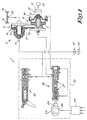
- Figure 1 schematically shows a device 1 for controlling a transmission unit 2 which is equipped with a belt variator 3.
- the belt variator 3 consists of a primary pulley 5 placed on an ingoing shaft 4 with at least one pulley half 6 which can be axially moved; a secondary pulley 8 placed on a driven shaft 7 with at least one pulley half 9 which can be axially moved; and an endless transmission element 10, such as a belt, provided between the pulleys 5 and 8, one and other such that the transmission ratio between the shafts 4 and 7 can be altered by axially moving the pulley halves 6 and 9.
- the ingoing shaft 4 is usually driven by means of a drive-off coupling 11 and a reversing unit 12 driven by the motor 13 of the motor vehicle concerned.
- the movement of the driven shaft 7 is transmitted onto a number of wheels 15 of the vehicle via a differential gear 14 or such.
- the pulley halves 6 and 9 are moved by means of hydraulic pressure cylinders working in conjunction therewith, a primary pressure cylinder 16 and a secondary pressure cylinder 17 respectively, whose pressures are regulated by means of a primary regulating valve 18 and a secondary regulating valve 19.
- the regulating valves 18 and 19 are part of a hydraulic regulating unit 20 which is fed in the known manner by means of a hydraulic medium under pressure which is pumped up from a reservoir 22 by means of a pump 21.
- the transmission ratio of the belt variator 3 is mainly controlled by means of the primary regulating valve 18 which is controlled in turn by a drive element 23 which receives signals from a control unit 24.
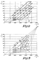
- the behaviour of the continuously variable transmission is, as explained in EP 0.697.548, characterized by what is called the variogram, i.e. a diagram in which the different operating conditions are represented as a function of the velocity V of the motor vehicle and the rotational speed n of the motor 13 or thus of the ingoing shaft 4.
- the variogram i.e. a diagram in which the different operating conditions are represented as a function of the velocity V of the motor vehicle and the rotational speed n of the motor 13 or thus of the ingoing shaft 4.
- control lines A-B-C-D-E-F are selected such that a handling is obtained which is clearly and deliberately different from the handling of a transmission unit which is provided with gears with fixed transmission ratios.
- control lines A-B-C-D-E-F are followed in said variogram which are selected such that, when gearing up and gearing down respectively, large rotational speed differences per transition are excluded between the selected control lines.
- control lines A-B-C-D-E-F are selected such that at least in a part of the operation field, the rotational speed differences which arise during the changing are identical or practically identical to one another, even with different vehicle speeds.
- the occurring rotational speed differences for all the above-mentioned transitions, between all the control lines are preferably identical to one another for the largest part of the operation field.
- the distances A1-A2, A2-A3, A3-A4, A4-A5, A5-A6 differ little from one another or are preferably equal to one another, and preferably also differ little from or are equal to the distances related to other velocities, such as for example the distances A7-A8, A9-A10, A11-A12, etc.
- these criteria are preferably to be complied with in an ideal manner, preferably the criteria which dictate that the rotational speed differences of the different transitions must be identical to one another, but it is also clear that the ideal circumstances can be deviated from while still obtaining an advantageous effect.
- these deviations per successive transition shall preferably not exceed 10% at the same velocity.
- control lines A-B-C-D-E-F are selected such that, in the above-mentioned part of the operation field, and better still in the entire operation field, the difference between the largest rotational speed difference and the smallest rotational speed difference is kept under 10% of the above-mentioned largest rotational speed difference.
- control lines A-B-C-D-E-F are followed which run parallel or almost parallel to one another for the largest part of the operation field.
- control lines A-B-C-D-E-F are preferably exactly parallel to one another, but that deviations may arise here as well while still remaining within the scope of the invention.
- these deviations are preferably restricted to deviations as far as parallelism is concerned which, in the case where the control lines A-B-C-D-E-F diverge away from the origin of the variogram in the above-mentioned part of the operation field, expressed as a change in the rotational speed per speed difference of 20 km/h, amount to 10% at the most, whereas in the case where the control lines A-B-C-D-E-F converge in the direction away from the origin, the deviation may exceed said 10%, as will become clear from the variogram described in figure 3.
- the distance A7-A8 may differ no more 10% from the distance A3-A4
- the distance A11-A12 may differ no more than 10% from the distance A7-A8, etc.
- the control is preferably carried out such that the operation field to which the variogram is related has a form whereby the right bottom angle 25, in particular the angle which is situated in the field which is characterized by low vehicle speeds and high rotational speeds, is round or cut off respectively.
- the right bottom angle 25 in particular the angle which is situated in the field which is characterized by low vehicle speeds and high rotational speeds, is round or cut off respectively.
- control lines A-B-C-D-E-F are made to converge towards the top, preferably into one and the same point P.
- the control lines A-B-C-D-E-F are made to converge towards the top, preferably into one and the same point P.
- the convergence or mutual approach between the control lines amounts to 30% at the most per speed difference of 20 km/h. This implies that for example the rotational speed difference determined by the distance A13-A14 deviates 30% at the most from the rotational speed difference which is determined by the distance A15-A16, and for example that nor the distance A17-A18 deviates more than 30% from the distance A19-A20.
- control lines in the central part of the variogram in other words over the largest part of their length, preferably run straight.
- the control lines concerned preferably also run parallel or almost parallel to one another, whereby the same deviations may be allowed for, however, as mentioned above for the top parts of the control lines A-B-C-D-E-F.
- the top control line F which coincides with what is called the "overdrive ratio", normally extends through the origin of the variogram.
- control lines A and F form two of the four limits of the operation field. All the other control lines are preferably related to and derived from the "Overdrive ratio”.
- the slope of the control lines shall be selected such that it exceeds 30 km/h per 1000 rev/min.
- the slope of the control line F is such that the speed difference belonging to the points B1 and B2 is larger than 30 km/h, which in this case is about 40 km/h.
- the part of the variogram onto which the above-mentioned criteria at least apply preferably consists of the central part of the variogram, in other words the part where most of the driving and gearing is done.
- control lines A-B-C-D-E-F are preferably selected such that the part of the variogram in which these control lines comply with the above-mentioned criteria forms at least 75% of the entire operation field.
- the entire operation field is meant in this context the surface of the variogram which is. situated between the control line A, the control line F, the lower transitions between the different control lines and the top transitions between the different control lines.
- control lines are selected such that the above-mentioned part of the operation field, in other words the part in which the control lines comply with the above-mentioned characteristics, coincides at least with the part of the operation field which is situated above 60 km/h in the variogram, and better still with the part which is situated above 40 km/h, in other words the part which is outlined in figure 2 with the dot and dash line L.
- embodiments are represented in figures 2 and 3 with six control lines, but it is clear that, according to variants, it is also possible to make embodiments with more or less than six control lines.
- An embodiment with six control lines is preferred, however, as the rotational speed differences per transition can be kept relatively small then. More than six control lines are less advantageous, however, as the driver will have to change more.
- the invention also concerns a device 1 for realizing the above-mentioned method.
- a device 1 for realizing the above-mentioned method.
- it consists basically in that use is made of a control unit 24 provided with the required control programs, such that when the "tip mode" is activated, control lines will automatically be followed which comply with the above-described method.
- the primary regulating valve 18 will be controlled to this end by means of a drive element 23 which is formed of an actuator.
- This actuator may for example consist of a stepping motor 26 which can axially move the valve discs 27 of the primary regulating valve 18 by means of a worm transmission 28.
- a stepping motor 26 which can axially move the valve discs 27 of the primary regulating valve 18 by means of a worm transmission 28.
- Such an actuator allows for a very precise control according to the set control line.
- the control unit 24 preferably makes sure that, when extreme limit values are reached, which may occur when the driver does not give the change signal in time, there will be an automatic transition to a higher or lower control line.
- transitions are meant theoretical transitions at one and the same speed, in other words horizontal transitions in the above-mentioned variogram.
Landscapes
- Engineering & Computer Science (AREA)
- General Engineering & Computer Science (AREA)
- Mechanical Engineering (AREA)
- Control Of Transmission Device (AREA)
Claims (24)
- Procédé pour commander le rapport de transmission d'un variateur de vitesse du type à courroie dans une unité de transmission pour un véhicule à moteur, comprenant l'étape consistant à commander le rapport de transmission dans un mode de basculement de telle sorte que le rapport de transmission est commandé en fonction de signaux de changement de vitesse fournis par un conducteur du véhicule à moteur, en suivant ainsi plusieurs lignes de commande fixes prédéterminées (A - B - C - D - E - F) conformément à un variogramme définissant un champ opérationnel englobant des vitesses du moteur, des vitesses du véhicule et une origine, caractérisé en ce que les lignes de commande (A - B - C - D - E - F) sont déterminées de telle sorte qu'une différence de vitesse de rotation du moteur dans chacune de plusieurs transitions successives entre les lignes de commande (A - B - C - D - E - F) à une vitesse particulière du véhicule (V) est essentiellement égale à la différence de vitesse de rotation dans une transition directement précédente lors d'une multiplication et lors d'une démultiplication.
- Procédé selon la revendication 1, caractérisé en ce que les lignes de commande (A - B - C - D - E - F) sont sélectionnées de telle sorte que, au moins dans une partie du champ opérationnel, les différences de vitesse de rotation mentionnées ci-dessus (A1 - A2, A2 - A3, A3 - A4, A4 - A5, A5 - A6, A7 - A8, A9 - A10, A11 - A12) sont pratiquement identiques l'une à l'autre pour la plupart des transitions, même à des vitesses du véhicule différentes.
- Procédé selon la revendication 2, caractérisé en ce que les lignes de commande (A - B - C - D - E - F) sont sélectionnées de telle sorte que, au moins dans une partie du champ opérationnel, les différences de vitesse de rotation mentionnées ci-dessus (A1 - A2, A2 - A3, A3 - A4, A4 - A5, A5 - A6, A7 - A8, A9 - A10, A11 - A12) sont pratiquement identiques l'une à l'autre pour toutes les transitions entre toutes les lignes de commande successives (A - B - C - D - E - F).
- Procédé selon l'une quelconque des revendications précédentes, caractérisé en ce que les lignes de commande (A - B - C - D - E - F) sont sélectionnées de telle sorte que les différences de vitesse de rotation sont identiques l'une à l'autre pour au moins une partie du champ opérationnel.
- Procédé selon l'une quelconque des revendications précédentes, caractérisé en ce que les lignes de commande (A - B - C - D - E - F) sont déterminées de telle sorte que ces lignes de commande s'étendent de manière essentiellement parallèle l'une à l'autre pour la majeure partie du champ opérationnel.
- Procédé selon la revendication 5, caractérisé en ce que lesdites lignes de commande (A - B - C - D - E - F) s'étendent de manière exactement parallèle l'une à l'autre pour ladite majeure partie du champ opérationnel.
- Procédé selon la revendication 1, caractérisé en ce que les lignes de commande (A - B - C - D - E - F) sont déterminées de telle sorte que, pour la majeure partie du champ opérationnel, au moins deux de ces lignes de commande (A - B - C - D - E - F), dans une direction s'écartant de l'origine du variogramme, divergent l'une par rapport à l'autre au maximum à concurrence de 10 %, exprimés comme changement de la vitesse de rotation par 20 km/heure de différence de vitesse du véhicule.
- Procédé selon la revendication 1, caractérisé en ce que les lignes de commande (A - B - C - D - E - F) sont déterminées de telle sorte que, pour la majeure partie du champ opérationnel, au moins deux de ces lignes de commande (A - B - C - D - E - F), dans une direction s'écartant de l'origine du variogramme, convergent l'une par rapport à l'autre.
- Procédé selon la revendication 8, caractérisé en ce qu'on suit des lignes de commande (A - B - C - D - E - F) qui convergent en un point (P).
- Procédé selon la revendication 8 ou 9, caractérisé en ce qu'on sélectionne des lignes de commande (A - B - C - D - E - F) dont la convergence et/ou l'approche par la différence de vitesse de 20 km/heure s'élève à un maximum de 30 %.
- Procédé selon l'une quelconque des revendications 2 à 10, caractérisé en ce que, dans la partie susmentionnée du champ opérationnel, la pente de toutes les lignes de commande est sélectionnée pour être supérieure à 30 km/heure par intervalle de 1000 tours/minute.
- Procédé selon l'une quelconque des revendications 2 à 11, caractérisé en ce qu'on suit plusieurs lignes de commande (A - B - C - D - E - F) qui représente des lignes rectilignes sur la majeure partie de leur longueur.
- Procédé selon l'une quelconque des revendications 2 à 12, caractérisé en ce que la partie susmentionnée du champ opérationnel représente la partie centrale du variogramme.
- Procédé selon l'une quelconque des revendications 2 à 13, caractérisé en ce qu'on sélectionne les lignes de commande de telle sorte que la partie susmentionnée du champ opérationnel, en d'autres termes la partie dans laquelle les lignes de commande répondent aux caractéristiques susmentionnées, représente au moins 75 % du champ opérationnel total.
- Procédé selon l'une quelconque des revendications 2 à 14, caractérisé en ce qu'on sélectionne les lignes de commande de telle sorte que la partie susmentionnée du champ opérationnel, en d'autres termes la partie dans laquelle les lignes de commande répondent aux caractéristiques susmentionnées, recouvre au moins la partie (L) du champ opérationnel qui est située au-dessus de 40 km/heure dans le variogramme.
- Procédé selon l'une quelconque des revendications précédentes, caractérisé en ce que la ligne de commande supérieure (F), en particulier la ligne de commande faisant partie de la "surmultiplication", passe par l'origine du variogramme.
- Procédé selon l'une quelconque des revendications précédentes, caractérisé en ce que la commande est mise en oeuvre de telle sorte que le champ opérationnel exclut des vitesses de rotation élevées à de petites vitesses du véhicule en coupant l'angle formé par un axe horizontal du variogramme et une ligne de commande (A) qui est située dans une région de petites vitesses du moteur et de grandes vitesses de rotation (figure 2).
- Procédé selon l'une quelconque des revendications précédentes, caractérisé en ce qu'une ligne de commande ou plusieurs lignes de commande sont courbées ou légèrement arrondies à leur base.
- Procédé selon la revendication 18, caractérisé en ce que plusieurs lignes de commande sont courbées ou légèrement arrondies à leur base et en ce que les parties inférieures s'étendent en parallèle ou pratiquement en parallèle l'une par rapport à l'autre.
- Procédé selon l'une quelconque des revendications précédentes, caractérisé en ce que le rapport de transmission est automatiquement modifié dans certains cas limites prédéterminés, de telle sorte que l'on obtient une transition automatique à une ligne de commande suivante, supérieure ou inférieure.
- Procédé de commande du rapport de transmission d'un variateur de vitesse du type à courroie dans une unité de transmission pour un véhicule à moteur, comprenant l'étape consistant à commander le rapport de transmission dans un mode de basculement de telle sorte que le rapport de transmission est commandé en fonction de signaux de changement de vitesse fournis par un conducteur du véhicule à moteur, en suivant ainsi plusieurs lignes de commande fixes prédéterminées (A - B - C - D - E - F) conformément à un variogramme définissant un champ opérationnel englobant des vitesses du moteur, des vitesses du véhicule et une origine, caractérisé en ce que les lignes de commande (A - B - C - D - E - F) sont déterminées de telle sorte qu'une différence de vitesse de rotation du moteur dans chacune de plusieurs transitions successives entre les lignes de commande (A - B - C - D - E - F) à une vitesse particulière du véhicule (V) diffère, par rapport à la différence de vitesse de rotation dans une transition directement précédente lors d'une multiplication et lors d'une démultiplication, d'une valeur qui est inférieure à 10 % de la plus grande différence de vitesse de rotation, parmi les deux différences de vitesse de rotation successives.
- Procédé selon la revendication 21, caractérisé en ce que, dans au moins une partie du champ opérationnel, la différence entre la plus grande différence de vitesse de rotation et la plus petite différence de vitesse rotation est maintenue en dessous de 10 % de la plus grande différence de vitesse rotation mentionnée ci-dessus.
- Dispositif pour la mise en oeuvre du procédé selon l'une quelconque des revendications précédentes, constitué par un variateur de vitesse du type à courroie comportant des poulies et une courroie associée et une unité de commande hydraulique (20) avec laquelle on peut modifier le rapport de transmission du variateur de vitesse (3) du type à courroie, par lequel des moitiés de poulies (6 - 9) sont en mesure de se déplacer en direction axiale et sont commandés à l'aide de cylindres pneumatiques (16 - 17) qui sont commandés, à leur tour, par au moins une soupape de réglage (18 - 19), caractérisé en ce que cette soupape de réglage (18) est commandée par un actionneur qui est commandé, à son tour, par une unité de commande électronique (24) qui garantit la mise en oeuvre d'une commande conformément aux lignes de commande et qui est conforme au procédé mentionné ci-dessus.
- Dispositif selon la revendication 23, caractérisé en ce que ladite unité de commande 24 est conçue pour la mise en oeuvre de deux procédés, plus précisément un procédé par lequel la commande est changée automatiquement d'une part et une commande par laquelle le procédé tel que décrit dans l'une quelconque des revendications 1 à 22 est appliqué d'autre part.
Applications Claiming Priority (2)
| Application Number | Priority Date | Filing Date | Title |
|---|---|---|---|
| BE9601027A BE1010795A3 (nl) | 1996-12-10 | 1996-12-10 | Werkwijze en inrichting voor het sturen van de overbrengingsverhouding van een riemvariator bij een transmissie-eenheid voor een motorvoertuig. |
| BE9601027 | 1996-12-10 |
Publications (2)
| Publication Number | Publication Date |
|---|---|
| EP0848191A1 EP0848191A1 (fr) | 1998-06-17 |
| EP0848191B1 true EP0848191B1 (fr) | 2003-02-26 |
Family
ID=3890136
Family Applications (1)
| Application Number | Title | Priority Date | Filing Date |
|---|---|---|---|
| EP97203657A Expired - Lifetime EP0848191B1 (fr) | 1996-12-10 | 1997-11-22 | Procédé et dispositif de commande du rapport d'un variateur à courroie dans une unité de transmission d'un véhicule automobile |
Country Status (7)
| Country | Link |
|---|---|
| US (1) | US6033339A (fr) |
| EP (1) | EP0848191B1 (fr) |
| JP (1) | JPH10184870A (fr) |
| KR (1) | KR19980063981A (fr) |
| AT (1) | ATE233380T1 (fr) |
| BE (1) | BE1010795A3 (fr) |
| DE (1) | DE69719298D1 (fr) |
Families Citing this family (7)
| Publication number | Priority date | Publication date | Assignee | Title |
|---|---|---|---|---|
| WO2000025042A1 (fr) * | 1998-10-23 | 2000-05-04 | Siemens Aktiengesellschaft | Procede et dispositif de commande pour une transmission automatique variable en continu d'automobile |
| DE19929693A1 (de) * | 1999-05-08 | 2000-11-16 | Zahnradfabrik Friedrichshafen | Verfahren zur manuellen Vorgabe der Übersetzung eines stufenlosen Getriebes |
| ATE259950T1 (de) * | 2000-05-03 | 2004-03-15 | Doornes Transmissie Bv | Stufenloses getriebe mit variabler übersetzungsspreizung |
| US6705961B2 (en) | 2000-07-14 | 2004-03-16 | Tecumseh Products Company | Variable speed transmission and electronic speed control therefor |
| FR2827026B1 (fr) * | 2001-07-06 | 2003-09-12 | Renault | Procede de commande d'une transmission automatique en fonction du profil de la route |
| JP4376034B2 (ja) * | 2003-11-04 | 2009-12-02 | 本田技研工業株式会社 | 車両用無段変速機の制御装置 |
| FR2873422B1 (fr) * | 2004-07-21 | 2007-09-28 | Renault Sas | Procede de controle des changements de rapport lors des communications de lois de passage ou de variogrammes |
Family Cites Families (10)
| Publication number | Priority date | Publication date | Assignee | Title |
|---|---|---|---|---|
| JPS6030855A (ja) * | 1983-07-30 | 1985-02-16 | Mazda Motor Corp | 無段変速機の制御装置 |
| JPS60125447A (ja) * | 1983-11-30 | 1985-07-04 | 富士重工業株式会社 | 無段変速機の変速比制御装置 |
| AU4329789A (en) * | 1988-10-07 | 1990-05-01 | Zahnradfabrik Friedrichshafen Ag | Regulating device and control unit for a continuously variable automatic transmission system |
| DE4312718A1 (de) * | 1993-04-20 | 1994-11-10 | Zahnradfabrik Friedrichshafen | Schaltvorrichtung für ein stufenloses Getriebe eines Kraftfahrzeuges |
| GB9320241D0 (en) * | 1993-10-01 | 1993-11-17 | Greenwood Christopher J | Improvements in or relating to vehicular drivelines including continuously variable-ratio transmissions |
| DE4411938A1 (de) * | 1994-04-07 | 1995-10-12 | Porsche Ag | Steuereinrichtung und Steuerverfahren für ein stufenloses Getriebe |
| JP3196498B2 (ja) * | 1994-05-02 | 2001-08-06 | アイシン・エィ・ダブリュ株式会社 | 車両用変速機の制御装置 |
| NL9401313A (nl) * | 1994-08-15 | 1996-03-01 | Doornes Transmissie Bv | Continu variabele transmissie. |
| DE4441878A1 (de) * | 1994-11-24 | 1996-05-30 | Porsche Ag | Steuereinrichtung und Steuerverfahren für ein stufenloses Getriebe |
| JP3633063B2 (ja) * | 1995-11-07 | 2005-03-30 | マツダ株式会社 | 自動変速機の制御装置 |
-
1996
- 1996-12-10 BE BE9601027A patent/BE1010795A3/nl not_active IP Right Cessation
-
1997
- 1997-11-22 EP EP97203657A patent/EP0848191B1/fr not_active Expired - Lifetime
- 1997-11-22 DE DE69719298T patent/DE69719298D1/de not_active Expired - Lifetime
- 1997-11-22 AT AT97203657T patent/ATE233380T1/de not_active IP Right Cessation
- 1997-11-26 US US08/979,555 patent/US6033339A/en not_active Expired - Fee Related
- 1997-12-09 JP JP9338822A patent/JPH10184870A/ja active Pending
- 1997-12-10 KR KR1019970067279A patent/KR19980063981A/ko not_active Withdrawn
Also Published As
| Publication number | Publication date |
|---|---|
| US6033339A (en) | 2000-03-07 |
| JPH10184870A (ja) | 1998-07-14 |
| EP0848191A1 (fr) | 1998-06-17 |
| DE69719298D1 (de) | 2003-04-03 |
| KR19980063981A (ko) | 1998-10-07 |
| ATE233380T1 (de) | 2003-03-15 |
| BE1010795A3 (nl) | 1999-02-02 |
Similar Documents
| Publication | Publication Date | Title |
|---|---|---|
| US7819764B2 (en) | Speed change control device for belt type continuously variable transmission and control method thereof | |
| US4999774A (en) | Speed ratio control system and method for a continuously variable transmission for a vehicle | |
| EP0306216A1 (fr) | Système de contrôle de vitesse pour un véhicule à transmission à réglage continu | |
| EP0291061B1 (fr) | Méthode et appareil de commande du rapport de transmission d'un variateur continu de vitesse | |
| EP0228897B1 (fr) | Système de commande du rapport de transmission pour une transmission continûment variable | |
| US6033339A (en) | Method and apparatus for controlling the transmission ratio of a belt variator in a transmission unit for a motor vehicle | |
| US4781655A (en) | System for controlling the pressure of oil in a system for a continuously variable transmission | |
| EP0841504A3 (fr) | Dispositif hydraulique de commande d'une transmission à variation continue | |
| EP0221668B1 (fr) | Système de contrôle d'une transmission à réglage en continu | |
| EP0207227B1 (fr) | Système de commande pour transmission continue | |
| EP0233781B1 (fr) | Commande des rappos de changement de vitesse d'une transmission continue | |
| US5924955A (en) | Continuously variable transmission controller | |
| EP0207603A1 (fr) | Système de commande pour une transmission continue | |
| US4751857A (en) | System for controlling the pressure of oil in a system for an infinitely variable transmission | |
| EP0207228B1 (fr) | Système de commande pour une transmission continue | |
| US6409628B1 (en) | Method and apparatus for preventing hunting between ranges in a continuously variable transmission | |
| GB2321938A (en) | Ratio control system of a continuously-variable transmission | |
| EP0435558A3 (fr) | Commande hydraulique pour une transmission à variation continue avec une soupape de passage à gain en relation avec la vitesse véhicule | |
| EP0336323A2 (fr) | Système de commande pour transmission | |
| US6447423B1 (en) | Method and apparatus for adjusting transmission ratio commands for a continuously variable transmission | |
| JP3395581B2 (ja) | 無段変速機の変速制御装置 | |
| US7066855B2 (en) | Line pressure control apparatus for continuously variable transmission | |
| EP0323174A3 (fr) | Système de commande de rapport de vitesse pour une transmission à variation de vitesse infinie | |
| EP2019012B1 (fr) | Transmission à rapports multiples | |
| JP3424505B2 (ja) | 無段変速機の変速制御装置 |
Legal Events
| Date | Code | Title | Description |
|---|---|---|---|
| PUAI | Public reference made under article 153(3) epc to a published international application that has entered the european phase |
Free format text: ORIGINAL CODE: 0009012 |
|
| AK | Designated contracting states |
Kind code of ref document: A1 Designated state(s): AT CH DE ES FR GB IT LI LU NL SE |
|
| AX | Request for extension of the european patent |
Free format text: AL;LT;LV;MK;RO;SI |
|
| 17P | Request for examination filed |
Effective date: 19981016 |
|
| AKX | Designation fees paid |
Free format text: AT CH DE ES FR GB IT LI LU NL SE |
|
| RBV | Designated contracting states (corrected) |
Designated state(s): AT CH DE ES FR GB IT LI LU NL SE |
|
| 17Q | First examination report despatched |
Effective date: 20000518 |
|
| GRAG | Despatch of communication of intention to grant |
Free format text: ORIGINAL CODE: EPIDOS AGRA |
|
| GRAG | Despatch of communication of intention to grant |
Free format text: ORIGINAL CODE: EPIDOS AGRA |
|
| GRAH | Despatch of communication of intention to grant a patent |
Free format text: ORIGINAL CODE: EPIDOS IGRA |
|
| GRAH | Despatch of communication of intention to grant a patent |
Free format text: ORIGINAL CODE: EPIDOS IGRA |
|
| GRAA | (expected) grant |
Free format text: ORIGINAL CODE: 0009210 |
|
| AK | Designated contracting states |
Designated state(s): AT CH DE ES FR GB IT LI LU NL SE |
|
| PG25 | Lapsed in a contracting state [announced via postgrant information from national office to epo] |
Ref country code: NL Free format text: LAPSE BECAUSE OF FAILURE TO SUBMIT A TRANSLATION OF THE DESCRIPTION OR TO PAY THE FEE WITHIN THE PRESCRIBED TIME-LIMIT Effective date: 20030226 Ref country code: LI Free format text: LAPSE BECAUSE OF FAILURE TO SUBMIT A TRANSLATION OF THE DESCRIPTION OR TO PAY THE FEE WITHIN THE PRESCRIBED TIME-LIMIT Effective date: 20030226 Ref country code: IT Free format text: LAPSE BECAUSE OF FAILURE TO SUBMIT A TRANSLATION OF THE DESCRIPTION OR TO PAY THE FEE WITHIN THE PRE;WARNING: LAPSES OF ITALIAN PATENTS WITH EFFECTIVE DATE BEFORE 2007 MAY HAVE OCCURRED AT ANY TIME BEFORE 2007. THE CORRECT EFFECTIVE DATE MAY BE DIFFERENT FROM THE ONE RECORDED.SCRIBED TIME-LIMIT Effective date: 20030226 Ref country code: FR Free format text: LAPSE BECAUSE OF NON-PAYMENT OF DUE FEES Effective date: 20030226 Ref country code: CH Free format text: LAPSE BECAUSE OF FAILURE TO SUBMIT A TRANSLATION OF THE DESCRIPTION OR TO PAY THE FEE WITHIN THE PRESCRIBED TIME-LIMIT Effective date: 20030226 Ref country code: AT Free format text: LAPSE BECAUSE OF FAILURE TO SUBMIT A TRANSLATION OF THE DESCRIPTION OR TO PAY THE FEE WITHIN THE PRESCRIBED TIME-LIMIT Effective date: 20030226 |
|
| REG | Reference to a national code |
Ref country code: GB Ref legal event code: FG4D |
|
| REG | Reference to a national code |
Ref country code: CH Ref legal event code: EP |
|
| REF | Corresponds to: |
Ref document number: 69719298 Country of ref document: DE Date of ref document: 20030403 Kind code of ref document: P |
|
| PG25 | Lapsed in a contracting state [announced via postgrant information from national office to epo] |
Ref country code: SE Free format text: LAPSE BECAUSE OF FAILURE TO SUBMIT A TRANSLATION OF THE DESCRIPTION OR TO PAY THE FEE WITHIN THE PRESCRIBED TIME-LIMIT Effective date: 20030526 |
|
| PG25 | Lapsed in a contracting state [announced via postgrant information from national office to epo] |
Ref country code: DE Free format text: LAPSE BECAUSE OF FAILURE TO SUBMIT A TRANSLATION OF THE DESCRIPTION OR TO PAY THE FEE WITHIN THE PRESCRIBED TIME-LIMIT Effective date: 20030527 |
|
| NLV1 | Nl: lapsed or annulled due to failure to fulfill the requirements of art. 29p and 29m of the patents act | ||
| PG25 | Lapsed in a contracting state [announced via postgrant information from national office to epo] |
Ref country code: ES Free format text: LAPSE BECAUSE OF FAILURE TO SUBMIT A TRANSLATION OF THE DESCRIPTION OR TO PAY THE FEE WITHIN THE PRESCRIBED TIME-LIMIT Effective date: 20030828 |
|
| PGFP | Annual fee paid to national office [announced via postgrant information from national office to epo] |
Ref country code: GB Payment date: 20031217 Year of fee payment: 7 |
|
| PGFP | Annual fee paid to national office [announced via postgrant information from national office to epo] |
Ref country code: FR Payment date: 20031223 Year of fee payment: 7 |
|
| PGFP | Annual fee paid to national office [announced via postgrant information from national office to epo] |
Ref country code: LU Payment date: 20031230 Year of fee payment: 7 |
|
| PLBE | No opposition filed within time limit |
Free format text: ORIGINAL CODE: 0009261 |
|
| STAA | Information on the status of an ep patent application or granted ep patent |
Free format text: STATUS: NO OPPOSITION FILED WITHIN TIME LIMIT |
|
| EN | Fr: translation not filed | ||
| 26N | No opposition filed |
Effective date: 20031127 |
|
| PG25 | Lapsed in a contracting state [announced via postgrant information from national office to epo] |
Ref country code: LU Free format text: LAPSE BECAUSE OF NON-PAYMENT OF DUE FEES Effective date: 20041122 Ref country code: GB Free format text: LAPSE BECAUSE OF NON-PAYMENT OF DUE FEES Effective date: 20041122 |
|
| GBPC | Gb: european patent ceased through non-payment of renewal fee |
Effective date: 20041122 |