EP0849727A2 - Optische Aufzeichnungsplatte - Google Patents
Optische Aufzeichnungsplatte Download PDFInfo
- Publication number
- EP0849727A2 EP0849727A2 EP97122322A EP97122322A EP0849727A2 EP 0849727 A2 EP0849727 A2 EP 0849727A2 EP 97122322 A EP97122322 A EP 97122322A EP 97122322 A EP97122322 A EP 97122322A EP 0849727 A2 EP0849727 A2 EP 0849727A2
- Authority
- EP
- European Patent Office
- Prior art keywords
- recording
- groove
- film
- group
- weight reduction
- Prior art date
- Legal status (The legal status is an assumption and is not a legal conclusion. Google has not performed a legal analysis and makes no representation as to the accuracy of the status listed.)
- Granted
Links
Images







Classifications
-
- G—PHYSICS
- G11—INFORMATION STORAGE
- G11B—INFORMATION STORAGE BASED ON RELATIVE MOVEMENT BETWEEN RECORD CARRIER AND TRANSDUCER
- G11B7/00—Recording or reproducing by optical means, e.g. recording using a thermal beam of optical radiation by modifying optical properties or the physical structure, reproducing using an optical beam at lower power by sensing optical properties; Record carriers therefor
- G11B7/24—Record carriers characterised by shape, structure or physical properties, or by the selection of the material
-
- G—PHYSICS
- G11—INFORMATION STORAGE
- G11B—INFORMATION STORAGE BASED ON RELATIVE MOVEMENT BETWEEN RECORD CARRIER AND TRANSDUCER
- G11B7/00—Recording or reproducing by optical means, e.g. recording using a thermal beam of optical radiation by modifying optical properties or the physical structure, reproducing using an optical beam at lower power by sensing optical properties; Record carriers therefor
- G11B7/24—Record carriers characterised by shape, structure or physical properties, or by the selection of the material
- G11B7/2407—Tracks or pits; Shape, structure or physical properties thereof
- G11B7/24073—Tracks
- G11B7/24079—Width or depth
-
- Y—GENERAL TAGGING OF NEW TECHNOLOGICAL DEVELOPMENTS; GENERAL TAGGING OF CROSS-SECTIONAL TECHNOLOGIES SPANNING OVER SEVERAL SECTIONS OF THE IPC; TECHNICAL SUBJECTS COVERED BY FORMER USPC CROSS-REFERENCE ART COLLECTIONS [XRACs] AND DIGESTS
- Y10—TECHNICAL SUBJECTS COVERED BY FORMER USPC
- Y10S—TECHNICAL SUBJECTS COVERED BY FORMER USPC CROSS-REFERENCE ART COLLECTIONS [XRACs] AND DIGESTS
- Y10S428/00—Stock material or miscellaneous articles
- Y10S428/913—Material designed to be responsive to temperature, light, moisture
-
- Y—GENERAL TAGGING OF NEW TECHNOLOGICAL DEVELOPMENTS; GENERAL TAGGING OF CROSS-SECTIONAL TECHNOLOGIES SPANNING OVER SEVERAL SECTIONS OF THE IPC; TECHNICAL SUBJECTS COVERED BY FORMER USPC CROSS-REFERENCE ART COLLECTIONS [XRACs] AND DIGESTS
- Y10—TECHNICAL SUBJECTS COVERED BY FORMER USPC
- Y10S—TECHNICAL SUBJECTS COVERED BY FORMER USPC CROSS-REFERENCE ART COLLECTIONS [XRACs] AND DIGESTS
- Y10S428/00—Stock material or miscellaneous articles
- Y10S428/914—Transfer or decalcomania
-
- Y—GENERAL TAGGING OF NEW TECHNOLOGICAL DEVELOPMENTS; GENERAL TAGGING OF CROSS-SECTIONAL TECHNOLOGIES SPANNING OVER SEVERAL SECTIONS OF THE IPC; TECHNICAL SUBJECTS COVERED BY FORMER USPC CROSS-REFERENCE ART COLLECTIONS [XRACs] AND DIGESTS
- Y10—TECHNICAL SUBJECTS COVERED BY FORMER USPC
- Y10S—TECHNICAL SUBJECTS COVERED BY FORMER USPC CROSS-REFERENCE ART COLLECTIONS [XRACs] AND DIGESTS
- Y10S430/00—Radiation imagery chemistry: process, composition, or product thereof
- Y10S430/146—Laser beam
Definitions
- an optical recording medium which is capable of recording/reproducing data thereon by using a laser radiation of a smaller wavelength, which is smaller than a current 780nm or 830nm wavelength, for a high-density recording.
- an optical recording disk using an organic pigment has advantages of its low costs and easy processing thereto.
- the recording film exhibits, in a thermogravimetric analysis, substantially no weight reduction at a temperature below a starting temperature of a main weight reduction, a reduction rate of 2% or more in the main weight reduction, and a total weight reduction of 30% or more, and exhibits, in a differential thermal analysis, an exothermic calorie peak between -10 ⁇ V/mg and +10 ⁇ V and a peak width of 20°C or less at exothermic calorie peak.
- the optical disk exhibits a distorted angle ⁇ of 15° or more in the reproduced signal reproduced at a linear speed of 4.9 m/s or above from a 10T or larger mark recorded at a linear speed of 4.9 m/s or above.
- glass or resin known in the art such as polycarbonate, polymethacrylates and amorphous polyolefine is used as a transparent substrate, which has a thickness of 0.6 ⁇ 0.03 mm, on which a guide groove or grooves are formed for a tracking servo technique.
- the guide groove preferably has a depth between 100nm and 200nm, more preferably larger than 140nm at its lower limit and smaller than 180nm at its higher limit, a groove width between 0.2 ⁇ m and 0.4 ⁇ m, and a track pitch between 0.7 ⁇ m and 1 ⁇ m.
- the guide groove preferably has a U-shape. An enough change cannot be obtained during a recording operation in the case of groove depth less than 100nm, which may result in an insufficient modulation factor.
- the reflectance of the guide groove is insufficient due to the large difference in reflectance between the land area and the groove area for the case of groove recording. A sufficient amplitude for a tracking error signal cannot be obtained in the case of groove width less than 0.2 ⁇ m, and moreover, a transcription efficiency of the groove geometry is not obtained from the stamper to the disks.
- the recording film is generally fabricated by spin-coating of the solution wherein an organic pigment etc. is solved in a solvent such as ethanol, 3-hydroxy-3-methyl-2-buthanone, diacetone alcohol, and fluorine based alcohol.
- a solvent such as ethanol, 3-hydroxy-3-methyl-2-buthanone, diacetone alcohol, and fluorine based alcohol.
- the solvent is preferably selected from a fluorine based alcohols having a boiling point between 100 °C and 150°C, and having three or more of carbons, e.g., 1H, 1H, 3H-tetrafluoro propanol, 1H, 1H, 5H-octafiuoropentanol, and 1H, 1H, 3H-hexafluorobutanol.
- the boiling point is below 100°C, since the solvent evaporates faster during the spin-coating, the coating liquid does not spread toward the outer disk area, outside the radius of 40nm for example, which results in a larger film thickness in the vicinity of the disk center to retard the disk characteristics. If the boiling point is above 150°C, the solvent less evaporates to result in a larger evaporation time or larger content of the solvent remaining in the recording film, which may generate a higher jitter and undesirable.
- the ratio of the film thickness at the groove area to the film thickness at the land area depends on the spin-coat conditions such as the solvent of the coat liquid, disk rotation during the spin-coating, air velocity, temperature, and the density and viscosity of the solution, and the depth and width of the groove. Accordingly, it is difficult to detect the film thickness at the groove area solely from the average film thickness or the film thickness at the land area and the groove depth at the coated film measured after the spin-coating. On the other hand, if the ratio of the groove depth after the spin-coating (or at the coated film) to the groove depth before the spin-coating (or at the substrate), the film thickness at the land area and the groove depth at the substrate can he detected, the film thickness at the groove area can be obtained accordingly.
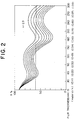
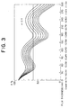
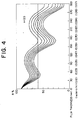
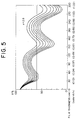
- the film thickness of the reflective film thus obtained was 100nm, which was the result after the film thickness of the recording film was changed between 0nm and 300nm.
- the scale on the abscissa is 30nm.
- the value of n abs ⁇ d/ ⁇ which is described layer, is also shown as the scale on the abscissa.
- the illustrated curves thus calculated are shown for the extinction coefficient between 0.03 and 0.1, with the scale of the extinction coefficient at 0.01.
- the curves of the reflectance (%) plotted against the film thickness comprises two interference mounds, wherein the same value for "n" provides a maximum at the same film thickness, and wherein the maximum value of the reflectance reduces as the "k" increases.
- the range for ⁇ C is between 0.12 and 0.75, whereas in the present invention, preferable range for ⁇ C is between 0.09 and 0.40.
- ⁇ C smaller than 0.09 which means a smaller thickness of the recording film, may not provide a sufficient recording sensitivity and a sufficient modulation factor.
- ⁇ C larger than 0.40 which means a larger thickness of the recording film, enlarges a recorded mark in both the directions of track and radius in the recorded section, which causes larger jitter and larger cross-talk.
- a preferable range for n abs is between 2.2 and 2.6 especially in the first aspect of the present invention. It is difficult to obtain a sufficient refractive index contrast for n abs below 2.2.
- a single pigment film which satisfies this range of n abs exhibits a maximum absorbance or step absorbance in a wavelength most adjacent to the recording/reproducing wavelength which is shorter than the recording/reproducing wavelength by 40 to 60nm.
- the single recording film exhibits an absorption spectrum, wherein A1/A0 is between 0.07 and 0.18 in the relationship between the optical absorbance A1 at the wavelength which is in the range of ⁇ 3nm from the recording/reproducing wavelength and an adjacent maximum absorbance or step absorbance A0 which is between 0.5 and 0.7.
- the ratio A1/A0 below 0.07 does not provide a sufficient absorption, which causes insufficient recording sensitivity, whereas the ratio exceeding 0.18 does not provide a sufficient reflectance due to an excess absorption and a stable tracking operation due to a small tracking error signal.
- A0 less than 0.5 does not provide a sufficient film thickness, whereas A0 exceeding 0.7 increases jitter due to a larger thickness.
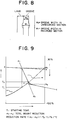
- the weight reduction rate is obtained as follows.
- An optical pigment having a mass of M0 is heated in a nitrogen ambient at a rate of 10 °C /minute (see Fig 9).
- the mass is reduced at a small rate in the initial period to trace a first substantially straight line a-b, then, reduced at a larger rate of more than 15% to trace a second substantially straight line d1-d2, which is called herein a main weight reduction.
- the starting temperature of the main weight reduction is designated by T1.
- the weight reduction is then slowed down to trace a third substantially straight line c-c.
- the weight reduction rate is expressed as follows: (m1-m2) (%) /(T2-T1) (°C), wherein T2 and m2 are the temperature and the mass at the intersection of the straight line d1-d2 and the straight line c-c, respectively, and m1 is the initial mass.
- the total weight reduction is expressed as (m1-m2) (%).
- alkyl group having 1 to 6 carbons which may be substituted by the halogen atom represented by Y 3
- Y 3 examples include methyl group, ethyl group, n-propyl group, isopropyl group, n-butyl group, sec-butyl group, tert-butyl group, n-heptyl group, n-hexyl group, chloromethyl group, dichloromethyl group, trichloromethyl group, trifluoromethyl group, bromomethyl group, methyl iodide group, 2, 2, and 2-trifluoroethyl group, perfluoroethyl group, and perfluoropropyl group.
- the electric conductivity was determined by measuring, using a four-pole method, a surface resistance R of a metallic film sputtered to a thickness of 100nm on a slide glass and the inverse of the specific electric resistance was calculated from the surface resistance R by the following formula: ( ⁇ /ln(2)) ⁇ R ⁇ t wherein "t" represents the film thickness.
- the electric conductivity thus obtained is larger than gold, and should be in the range between 0.20/ ⁇ V ⁇ cm and 0.30/ ⁇ V ⁇ cm.
- the metallic film should have a high reflectance, and the refractive index and extinction coefficient of the metallic film should be in the range between 0.1 and 0.2 and the range between 3 and 5, respectively, at the reproducing wavelength.
- the metallic reflective film should have a high reflectance for the laser light transmitted through a transparent substrate and have a high refractive index "n” and an extinction coefficient "k” between 0.1 and 0.2 and between 4 and 5, respectively, at a recording/reproducing wavelength between 500nm and 700nm.
- Preferable material for the metallic reflective layer is silver or a silver based alloy because, among other metals, silver has a high thermal conductivity, which suppresses the temperature rise by a large quenching effect, suppresses the extension of the transformation of the substrate, and reduces the cross-talk.
- silver has a higher reflectance than gold and aluminum alloys, and provides a high signal amplitude even from a small bit length, thereby exhibiting excellent characteristics especially for the small bit length.
- one or more additive elements such as Ti, Rh, Cu, Ta, Pd, Ni, V, Co, Cr, Si, C, B, Sn, P, Zn, Sb, and Mo may be preferably added in the silver below 10 atomic % of silver.
- the film thickness of the metallic reflective film is preferably equal to or more than 80nm, which does not provide an excess suppression of the transformation of the recording film nor degrades recording characteristics thereof.
- the fourth aspect of the present invention will be described.
- Recording at a linear speed as high as equal to or above 4.9m/s involves a new problem.
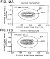
- the reproducing speed for a current DVD-RAM is between 3.7 and 3.8m/s, which is referred to as a one-time speed herein. If the reproducing speed is increased from the current speed up to or above 4.9m/s, the temperature distribution exhibits a different aspect in the longitudinal direction of the mark compared to the one-time speed, as will be understood from the comparison between Fig. 12A and Fig. 12B.
- the recording power level and the maximum temperature must be raised accordingly in order to finish the recording in a smaller time length.
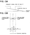
- the temperature gradient in the longitudinal direction of the mark becomes large as the linear speed increases, which involves an excess distortion of the pigment and the substrate, generating an asymmetrical distortion in the reproduced signal in the longitudinal direction, as shown in Figs. 13A and 13B.
- the distortion is especially remarkable in the range of a 10T mark or larger mark in the case of a mark length recording scheme.
- the distortion in the signal waveform retards the design for the optimum power level and increases the jitter.
- the present inventors examined correspondence of the distortion in the longitudinal direction of the mark in the reproduced signal to the shape of the distortion in the recorded section to find that, in the deformation or distortion of the substrate in the recorded section for the case of a linear speed of 4.9m/s or above and the case of a 11T or larger mark without using a pulse division technique, excellent recording characteristics can be obtained when: (i) only a moderate slope exists in the recorded section without a depression; or if the distortion is present, (ii) the depression has an edge disposed in the leading edge of the mark as viewed in the direction of reading, (iii) the depression has a center disposed in the central position of the mark, i.e., within ⁇ 10% of the total mark length from the center of the mark as viewed in the direction of reading, or (iv) the half-height width of the depression occupies a quarter of the mark length or above. On the other hand, if the distortion of the substrate for the 10T mark or longer mark is outside the specified ranges, it is likely that excellent
- the distortion in the signal waveform from a long mark generally appears in a higher linear speed range and does not appear in a lower linear speed range as in the case of CD, or one-time speed, provided that a sufficient groove width is secured.
- This distortion phenomenon is different from the distortions in the mark discussed in JP-A-7-65378 or JP-A-7-98887 for the CD-R disk in its mechanisms, and is considered peculiar to the write-once disk of a small wavelength having organic pigment, such as DVD-R.
- the distortion of the substrate in the recorded section is measured by AFM recording.
- the half-height is determined from the higher protrusion and the lowest portion, whereas if the difference exceeds 25%, the half-height is determined from the lower protrusion and the lowest portion after the depth of the lower protrusion measured from the lowest portion is multiplied by the ratio of the height of the higher protrusion to the height of the lower protrusion both measured from the lowest portion.
- the ratio of w/L is also used for the reference.
- the same dye solution was spin-coated on a substrate having a track pitch of 0.8 ⁇ m under similar conditions, annealed at 80°C for an hour, and subjected to measurement of the absorbance with reference to a similar substrate.
- the bonded disk was then peeled off at the interface, the reflective film was flaked off using a two-sided tape, the pigment was flushed away using ethanol, and the transformation of the substrate was observed in the recorded section by an AFM.
- the AFM showed a 20nm convex projection and a transformation of the groove width, which was as low as 1.4 times the groove width at the unrecorded section and thereby formed an excellent small recording mark.
- a bonded disk was fabricated in the present embodiment similarly to Embodiment 1 except for the rotational speed of the substrate during spin-coating of the dye solution, which was 600rpm. in the present embodiment.
- the film thickness d land of the recording film at the land area was 95nm
- the groove depth d film at the recording film was 78% of the groove depth d sub at the substrate, which corresponded to a film thickness d film of 128nm at the groove area.
- the cross-talk and transformation of the recorded section of the substrate were similar to those of Embodiment 1.
- the refractive index "n” and extinction coefficient "k” of the single- layer pigment were 2.5 and 0.05, respectively, at a 640nm wavelength.
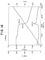
- the weight reduction of the pigment in the main weight reduction process, weight reduction rate, starting temperature of the main weight reduction and the total weight reduction were 37.6%, 2.6%/°C, 330°C and 45.7%, respectively.
- the refractive index "n” and extinction coefficient "k” of the single-layer pigment were 2.6 and 0.05, respectively, at a 640nm wavelength, and the absorption peak was at 595nm.
- the bonded disk was subjected to recording similarly to Embodiment 1 in similar conditions, resulting in a poor reflectance as low as 40%, jitter as high as 15ns which retarded recording of a small mark length.
- the reflectance of the disk was 640nm and corresponded to the second interference mound shown in Fig. 4, in view that "n" and "k” were 2.5 and 0.05, respectively.
- the value of n abs ⁇ d groove / ⁇ was 0.73, and ⁇ C was 0.26.
- the starting temperature of the main weight reduction of the recording film was 302°C, which corresponded to Fig. 8, the main weight reduction was 59.8%, the temperature difference was 5.49°C, and accordingly, the weight reduction rate was 10.9%/°C and the total weight reduction was 59.8%.
- the refractive index "n” and extinction coefficient "k” of the single layer pigment were 2.4 and 0.1, respectively.
- the film thicknesses d groove , d land at the groove area and the land area were about 90nm and 140nm, respectively.
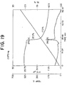
- the starting temperature of the main weight reduction of the recording film was 284°, the weight reduction in the main weight reduction was 56.9%, the temperature difference was 3.6°C, the total weight reduction was 59.8%, and accordingly, the weight reduction rate was 15.8%/°C.
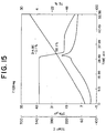
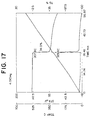
- a recording film was formed on a polycarbonate substrate of a 0.6mm thick, which comprised a U-shaped guide groove having a guide depth of 150nm and a groove width of 0.25 ⁇ m (half depth value) with a 0.80 ⁇ m pitch as measured by an AFM, by spin-coating liquid pigment, wherein 0.06g of a metal-containing azo pigment having a chemical structure expressed as follows: was dissolved in 5g of octafluoropentanol (OFP). The resultant recording layer was spin-coated at 800 rpm, annealed for an hour in an oven at 80°C. The weight reduction characteristic of the pigment is shown in Fig.
- the recording layer gold is sputtered to a thickness of 100nm, and the groove depth at the recording film was measured by using an AFM, which showed that the groove depth d film at the film was 55% of the groove depth d sub at the substrate.
- the film thickness d land at the land area was 80nm, and accordingly, the film thickness d film at the groove area corresponded to 140nm.
- a UV-cured resin SD-318 from Dainippon Ink And Chemicals, Incorporated
- EFM signal n-1T
- I top 50%
- I ll /R top 68%
- jitter of 9ns for 3T pulse were obtained.
- Each of the following embodiments and comparative examples had a substrate and a UV-cured resin film similar to those used in Embodiment 1, and had a reflective film made of gold of 100nm in thickness except for Embodiment 9, which had a reflective film made of silver of 100nm in thickness.
- the pigment used therein had chemcial structures shown below, and the recording conditions are similar to those used in Embodiment 1.
- the recording characteristics observed are shown in Table 1, wherein the cross-talk are calculated as a ratio (%) of the signal amplitude at the land area to the signal amplitude at the groove area on which a signal is recorded for sandwiching the land area.
- the recording power level was 7.4mW, 6.6mW, 8.6mW, 6.4mW, 6.5mW and 6.5mW, respectively, and in Comparative Examples, the recording power level was 7.2mW, 7.0mW and 7.2mW, respectively.
- optical disks according to the embodiments of the present invention are preferably used in an optical disk drive having a laser source lasing at a wavelength between 500nm and 700nm.
- the weight reduction property of the pigment is such that the weight reduction in the main weight reduction process, temperature difference, weight reduction rate, and starting temperature of the main weight reduction process were 41.0%, 3.6°C, 11.4%/°C, and 347°C, respectively.
- the thermogravimetric analysis (TGA) was effected by using a differential thermal analyzer (TG-DTA-320 in SSC5200H series from Seiko Electronic Corp).
- the refractive index "n” and extinction coefficient "k” of the single layer pigment thus obtained were 2.4 and 0.06, respectively, at a 640nm wavelength, and the absorption peak occurred at a 588nm wavelength.
- the bonded disk was then peeled off at the interface, the reflective film was flaked off using a two-sided tape, the pigment was flushed away using ethanol, and the transformation of the substrate was observed in the recorded section by an AFM.
- the AFM showed a 20nm convex projection, a peak of the depression located behind the center of the mark by 5.4% in the recorded section recorded at 3.7m/s linear speed, another peak of the depression located behind the center of the mark by 5.5% in the recorded section recorded at 4.7m/s linear speed, and a half-height width of 0.32
- the refractive index "n” and extinction coefficient "k” of the single-layer pigment were 2.36 and 0.06, respectively, at a 640nm wavelength, and an absorbance maximum occurred at a wavelength of 595.5nm.
- the film thickness d land of the recording film at the land area was 35nm
- the groove depth d film at the recording film was 57% of the groove depth d sub at the substrate
- the film thickness d groove of the recording film at the groove area corresponded to 110nm.
- the same disk was subjected to recording of a 11T mark at a linear speed of 4.9m/s and a recording power level of 72mW, and exhibited a distorted angle ⁇ as low as 11°. Protrusions of almost 20nm height were found as the distortion of the substrate in the recorded section, including a depression therebetween.
- the starting temperature of the main weight reduction for the pigment was 305°C in a nitrogen ambient, the weight reduction in the main reduction process was 47.7%, the temperature difference was 16.0°C, and the weight reduction rate was 2.98%/°C.
- the refractive index "n” and extinction coefficient "k” of the single-layer pigment were 2.5 and 0.08, respectively, at a 640nm wavelength, and an absorbance maximum occurred at a wavelength of 599.5nm.
- the film thickness is selected same as in Embodiment 11.
- a disk was fabricated similarly to Embodiment 13 except for a reflective film which was made of silver instead of gold, subjected to recording of a 11T mark at a linear speed of 4.9m/s, and exhibited a distorted angle ⁇ of 3° and a distortion in the recorded section similar to the case of Embodiment 13.
- R top was 42%.
- a disk was fabricated similarly to Embodiment 12 except for the reflective film which was made of silver instead of gold, subjected to recording similarly to Embodiment 14, and exhibited a distorted angle ⁇ of 14° which was slightly inferior to the case of Embodiment 12.
- the peak location of the depression in the recorded section was similar to Embodiment 12, the half-height width was 0.36nm which was slightly inferior to Embodiment 12.
- the film thickness was 90nm at the groove, and the groove depth d film at the coated film was 59% of the groove depth d sub at the substrate.
- the pigment exhibited an absorbance maximum at a 595.5 nm wavelength, and the refractive index "n” and extinction coefficient "k” of the single-layer pigment were 2.4 and 0.06, respectively, at a 640nm wavelength.
- the starting temperature of the main weight reduction for the pigment was 307°C in a nitrogen ambient, the weight reduction in the main reduction process was 52.3%, the temperature difference was 10.7°C, and the weight reduction rate was 4.89%/°C.
- the film thickness was similar to that in Embodiment 11.
- the method for the synthesis of the pigment included a refinement step of suspended washing in methanol, which provided an excellent weight reduction characteristic for the pigment, wherein the starting temperature of the main weight reduction for the pigment was 286°C in a nitrogen ambient, the weight reduction in the main reduction process was 43%, the temperature difference was 4.8°C, the weight reduction rate was 8.9%/°C and the pigment exhibited no weight reduction below the main weight reduction.
- the pigment exhibited an absorbance maximum at a 584nm wavelength, and the refractive index "n" and extinction coefficient "k” of the single-layer pigment were 2.3 and 0.06, respectively, at a 640nm wavelength.
- the resultant disk was subjected recording of a 11T mark at a linear speed of 4.9m/s and a recording power level of 8.6mW, similarly to Embodiment 11, and exhibited a distorted angle ⁇ as low as 5°.
- the distortion of the substrate was similar to that in Embodiment 11 except for the peak located 5.2% behind the center of the mark and a half-height width of 0.34nm, wherein a difference in the depression was not found between the marks 10T and 11T.
- a bonded disk was fabricated similarly to Embodiment 13 except for the pigment which had a chemical structure represented by the following formula:
- the distorted angle ⁇ in the reproduced signal from a 11T mark recorded at 3.7 m/s was as low as 3°, and accordingly, a percent jitter below 10% was obtained even without using a pulse division technique.
- the pigments according to the above Embodiments for the fourth aspect of the present invention there was no weight reduction observed outside the main weight reduction, or below the starting temperature of the main weight reduction, exhibiting excellent characteristics of the pigments.
- a bonded disk was fabricated similarly to Embodiment 11 except for the pigment which had a structure represented by the following formula:
- the starting temperature of main weight reduction in a nitrogen ambient, the weight reduction in the main weight reduction process and the temperature difference were 34.6°C, 42.5% and 5.3°C, respectively, which provided a reduction rate of 7.94%/°C by calculation.
- the resultant disk was subjected to EFM recording similarly to Embodiment 11 at 4.9 m/s, and exhibited a percent jitter of 9.8%.
- Recording of a 11T mark at 4.9 m/s provided a distorted angle ⁇ of 21° at a recording power level of 7.2mW, which was not acceptable.
- the distortion of the substrate in the recorded section was such that a part of a protrusion of around 20nm height was depressed, and although the peak of the depression was located only 7.7% behind the center of the protrusion, the depression had a significant asymmetry wherein the leading edge thereof is especially depressed to a large extent and the half-height width was 0.2nm.
- a bonded disk was fabricated similarly to Comparative Example 7 except for addition of 0.0066g of an additive agent into the pigment, the additive agent having a structure expressed as follows: Recording of a 11T mark to the resultant disk exhibited an acceptable distorted angle of 8°, which was superior to Comparative Example 7. The distortion of the substrate in the recorded section was such that a depression was not observed in a protrusion of around 20nm height and a moderate down slope was observed from the rear edge to the leading edge of the mark.
- the TG-DTA curve in a nitrogen ambient for the disk having the additive agent was similar to that of the disk before addition of the additive agent, and the starting temperature of the main weight reduction process for the disk after addition of the additive agent was 349°C.
- the main weight reduction process as used in the text means a weight reduction of more than 18% of the total weight.
Landscapes
- Optical Record Carriers And Manufacture Thereof (AREA)
- Investigating Or Analyzing Materials Using Thermal Means (AREA)
Applications Claiming Priority (4)
| Application Number | Priority Date | Filing Date | Title |
|---|---|---|---|
| JP338199/96 | 1996-12-18 | ||
| JP33819996A JP3666152B2 (ja) | 1996-12-18 | 1996-12-18 | 光記録媒体 |
| JP7355/97 | 1997-01-20 | ||
| JP9007355A JPH10208303A (ja) | 1997-01-20 | 1997-01-20 | 光記録媒体 |
Publications (3)
| Publication Number | Publication Date |
|---|---|
| EP0849727A2 true EP0849727A2 (de) | 1998-06-24 |
| EP0849727A3 EP0849727A3 (de) | 1998-08-26 |
| EP0849727B1 EP0849727B1 (de) | 2006-03-15 |
Family
ID=26341632
Family Applications (1)
| Application Number | Title | Priority Date | Filing Date |
|---|---|---|---|
| EP97122322A Expired - Lifetime EP0849727B1 (de) | 1996-12-18 | 1997-12-17 | Optische Aufzeichnungsplatte |
Country Status (3)
| Country | Link |
|---|---|
| US (1) | US6232036B1 (de) |
| EP (1) | EP0849727B1 (de) |
| DE (1) | DE69735460T2 (de) |
Cited By (5)
| Publication number | Priority date | Publication date | Assignee | Title |
|---|---|---|---|---|
| EP0875888A1 (de) * | 1997-04-28 | 1998-11-04 | Ricoh Company, Ltd. | Optisches Aufzeichnungsmedium, und dieses benutzende Aufzeichnungs- und/oder Reproduktions-Methode |
| EP1039456A1 (de) * | 1999-03-15 | 2000-09-27 | Fuji Photo Film Co., Ltd. | Beschreibbare digitale Videodisk (DVD) |
| WO2002080164A1 (en) * | 2001-03-28 | 2002-10-10 | Bayer Aktiengesellschaft | Optical recording medium |
| WO2004084204A3 (en) * | 2003-03-18 | 2005-03-17 | Koninkl Philips Electronics Nv | Optical information carrier comprising thermochromic or photochromic material |
| EP1690958A4 (de) * | 2003-10-16 | 2008-09-10 | Ishifuku Metal Ind | Sputtertargetmaterial |
Families Citing this family (23)
| Publication number | Priority date | Publication date | Assignee | Title |
|---|---|---|---|---|
| JP2002510836A (ja) * | 1998-04-06 | 2002-04-09 | イメイション・コーポレイション | データ記憶ディスク用リバース光マスタリング |
| US6905750B2 (en) * | 1998-06-22 | 2005-06-14 | Target Technology Company, Llc | Metal alloys for the reflective or the semi-reflective layer of an optical storage medium |
| US7314657B2 (en) * | 2000-07-21 | 2008-01-01 | Target Technology Company, Llc | Metal alloys for the reflective or the semi-reflective layer of an optical storage medium |
| US7045187B2 (en) * | 1998-06-22 | 2006-05-16 | Nee Han H | Metal alloys for the reflective or the semi-reflective layer of an optical storage medium |
| US7384677B2 (en) * | 1998-06-22 | 2008-06-10 | Target Technology Company, Llc | Metal alloys for the reflective or semi-reflective layer of an optical storage medium |
| US6852384B2 (en) * | 1998-06-22 | 2005-02-08 | Han H. Nee | Metal alloys for the reflective or the semi-reflective layer of an optical storage medium |
| TW561115B (en) * | 1999-09-08 | 2003-11-11 | Fuji Photo Film Co Ltd | Optical information recording medium |
| JP2001118289A (ja) * | 1999-10-20 | 2001-04-27 | Seiko Epson Corp | 光ディスク |
| AU2001232278A1 (en) * | 2000-02-14 | 2001-08-20 | Taiyo Yuden Co. Ltd. | Optical information recording medium |
| US7374805B2 (en) * | 2000-07-21 | 2008-05-20 | Target Technology Company, Llc | Metal alloys for the reflective or the semi-reflective layer of an optical storage medium |
| US7316837B2 (en) * | 2000-07-21 | 2008-01-08 | Target Technology Company, Llc | Metal alloys for the reflective or the semi-reflective layer of an optical storage medium |
| US7314659B2 (en) * | 2000-07-21 | 2008-01-01 | Target Technology Company, Llc | Metal alloys for the reflective or semi-reflective layer of an optical storage medium |
| US6771579B2 (en) | 2000-09-01 | 2004-08-03 | Mitsubishi Chemical Corporation | Optical recording method and optical recording medium |
| TWI292910B (de) * | 2001-06-11 | 2008-01-21 | Sony Corp | |
| AU2003241782A1 (en) * | 2002-05-31 | 2003-12-19 | Matsushita Electric Industrial Co., Ltd. | Optical recording medium, optical information processor and optical recording/reproducing method |
| US7572517B2 (en) * | 2002-07-08 | 2009-08-11 | Target Technology Company, Llc | Reflective or semi-reflective metal alloy coatings |
| AU2003248890A1 (en) * | 2002-07-08 | 2004-01-23 | Academy Corporation | Reflective or semi-reflective metal alloy coatings |
| CN100430215C (zh) * | 2003-04-18 | 2008-11-05 | 目标技术有限公司 | 光学存储介质反射层或半反射层用金属合金 |
| WO2004097821A1 (de) * | 2003-05-02 | 2004-11-11 | Interaxia Ag | Aufzeichnungsmedium für optischen datenspeicher, insbesondere für dvd±r |
| JP2004362644A (ja) * | 2003-06-03 | 2004-12-24 | Fuji Photo Film Co Ltd | 光情報記録方法 |
| TW200514070A (en) * | 2003-09-03 | 2005-04-16 | Williams Advanced Materials Inc | Silver alloys for optical data storage and optical media containing same |
| CN101045825A (zh) * | 2003-09-11 | 2007-10-03 | 三菱化学株式会社 | 偶氮金属螯合染料及光学记录媒体 |
| JP5426173B2 (ja) * | 2007-01-12 | 2014-02-26 | 新日鉄住金マテリアルズ株式会社 | Mo系スパッタリングターゲット板,および,その製造方法 |
Family Cites Families (26)
| Publication number | Priority date | Publication date | Assignee | Title |
|---|---|---|---|---|
| KR0159908B1 (ko) * | 1990-05-17 | 1999-02-18 | 에또오 다께또시 | 금속 킬레이트 화합물 및 그것을 이용한 광학적 기록 매체 |
| DE69112337T2 (de) * | 1990-05-25 | 1996-05-02 | Mitsubishi Chem Corp | Farbstoffzusammensetzung und optisches aufzeichnungsmedium. |
| US5500301A (en) * | 1991-03-07 | 1996-03-19 | Kabushiki Kaisha Kobe Seiko Sho | A1 alloy films and melting A1 alloy sputtering targets for depositing A1 alloy films |
| JP3019469B2 (ja) * | 1991-06-10 | 2000-03-13 | 三菱化学株式会社 | 光記録媒体 |
| JP3175279B2 (ja) * | 1992-04-02 | 2001-06-11 | 三菱化学株式会社 | 金属キレート化合物および該化合物を用いた光学記録媒体 |
| JP3199486B2 (ja) * | 1992-06-30 | 2001-08-20 | ティーディーケイ株式会社 | 光記録ディスク |
| DE69326525T2 (de) * | 1992-11-17 | 2000-01-27 | Mitsubishi Chemical Corp., Tokio/Tokyo | Magnetooptischer Aufzeichnungträger und Verfahren zur Aufzeichnung und Wiedergabe von optischer Information |
| CA2110233C (en) * | 1992-12-02 | 1999-01-12 | Mitsui Toatsu Chemicals, Incorporated | Optical information recording medium and composition for optical information recording film |
| JPH07141693A (ja) * | 1993-09-22 | 1995-06-02 | Toshiba Corp | 情報記録媒体 |
| DE69423728T2 (de) * | 1994-01-19 | 2000-11-16 | Kabushiki Kaisha Toshiba, Kawasaki | System mit optischer Platte und Gerät für optische Platte |
| JPH07266705A (ja) * | 1994-03-31 | 1995-10-17 | Tdk Corp | 光記録ディスク |
| US5633106A (en) * | 1994-04-08 | 1997-05-27 | Mitsui Toatsu Chemicals, Inc. | Optical recording media and a method of recording and reproducing information |
| JPH08258418A (ja) * | 1995-03-20 | 1996-10-08 | Hitachi Ltd | 情報記録用媒体 |
| JPH08332772A (ja) * | 1995-06-06 | 1996-12-17 | Mitsubishi Chem Corp | 光記録媒体 |
| JPH08339573A (ja) * | 1995-06-13 | 1996-12-24 | Mitsui Toatsu Chem Inc | 光記録媒体 |
| TW340864B (en) * | 1995-07-20 | 1998-09-21 | Mitsui Toatsu Chemicals | Optical recording medium |
| JP3731244B2 (ja) * | 1996-04-03 | 2006-01-05 | 三菱化学株式会社 | 光記録媒体及びその製造法 |
| JPH0981966A (ja) * | 1995-09-13 | 1997-03-28 | Mitsubishi Chem Corp | 光記録媒体 |
| JP3543464B2 (ja) * | 1996-01-16 | 2004-07-14 | 三菱化学株式会社 | 光記録媒体及び情報記録方法 |
| JPH0958123A (ja) * | 1995-08-22 | 1997-03-04 | Mitsubishi Chem Corp | 光記録媒体 |
| JPH106644A (ja) * | 1996-06-20 | 1998-01-13 | Mitsubishi Chem Corp | 光記録媒体 |
| JP3648823B2 (ja) * | 1996-01-18 | 2005-05-18 | 三菱化学株式会社 | 光学記録媒体及び情報記録方法 |
| US5858613A (en) * | 1996-01-23 | 1999-01-12 | Tdk Corporation | Optical recording medium |
| JPH09254543A (ja) * | 1996-03-21 | 1997-09-30 | Mitsubishi Chem Corp | 光記録媒体 |
| US5862123A (en) * | 1996-06-14 | 1999-01-19 | Mitsubishi Chemical Corporation | Optical phase-change disc |
| JP3486709B2 (ja) * | 1996-06-21 | 2004-01-13 | 株式会社リコー | 光記録媒体 |
-
1997
- 1997-12-17 EP EP97122322A patent/EP0849727B1/de not_active Expired - Lifetime
- 1997-12-17 DE DE69735460T patent/DE69735460T2/de not_active Expired - Lifetime
- 1997-12-18 US US08/992,899 patent/US6232036B1/en not_active Expired - Lifetime
Cited By (12)
| Publication number | Priority date | Publication date | Assignee | Title |
|---|---|---|---|---|
| EP0875888A1 (de) * | 1997-04-28 | 1998-11-04 | Ricoh Company, Ltd. | Optisches Aufzeichnungsmedium, und dieses benutzende Aufzeichnungs- und/oder Reproduktions-Methode |
| US6057020A (en) * | 1997-04-28 | 2000-05-02 | Ricoh Company, Ltd. | Optical recording medium and recording and/or reproduction method using the same |
| EP1039456A1 (de) * | 1999-03-15 | 2000-09-27 | Fuji Photo Film Co., Ltd. | Beschreibbare digitale Videodisk (DVD) |
| WO2002080164A1 (en) * | 2001-03-28 | 2002-10-10 | Bayer Aktiengesellschaft | Optical recording medium |
| US6936325B2 (en) | 2001-03-28 | 2005-08-30 | Sony Corporation | Optical recording medium |
| WO2004084204A3 (en) * | 2003-03-18 | 2005-03-17 | Koninkl Philips Electronics Nv | Optical information carrier comprising thermochromic or photochromic material |
| EP1690958A4 (de) * | 2003-10-16 | 2008-09-10 | Ishifuku Metal Ind | Sputtertargetmaterial |
| US7959746B2 (en) | 2003-10-16 | 2011-06-14 | Ishifuku Metal Industry Co., Ltd. | Sputtering target material |
| US8252127B2 (en) | 2003-10-16 | 2012-08-28 | Ishifuku Metal Industry Co., Ltd. | Sputtering target material |
| US20130094990A1 (en) * | 2003-10-16 | 2013-04-18 | Ishifuku Metal Industry Co., Ltd. | Sputtering target material |
| US8858877B2 (en) | 2003-10-16 | 2014-10-14 | Ishifuku Metal Industry Co., Ltd. | Sputtering target material |
| US9127346B2 (en) | 2003-10-16 | 2015-09-08 | Ishifuku Metal Industry Co., Ltd. | Sputtering target material |
Also Published As
| Publication number | Publication date |
|---|---|
| US6232036B1 (en) | 2001-05-15 |
| EP0849727B1 (de) | 2006-03-15 |
| EP0849727A3 (de) | 1998-08-26 |
| DE69735460D1 (de) | 2006-05-11 |
| DE69735460T2 (de) | 2006-11-16 |
Similar Documents
| Publication | Publication Date | Title |
|---|---|---|
| EP0849727B1 (de) | Optische Aufzeichnungsplatte | |
| KR100401282B1 (ko) | 광기록매체 | |
| US6811948B2 (en) | Thin-film design for optical recording media | |
| TW200305874A (en) | Optical recording medium and method for optically recording information in the same | |
| US6214519B1 (en) | Optical recording medium | |
| EP1310953B1 (de) | Aufzeichnungselement auf Basis von Phasenänderung für Anwendungen mit einmaliger Beschreibbarkeit | |
| EP1283522B1 (de) | WORM-Phasenänderungaufzeichnungselement | |
| US5449589A (en) | Method of making an optical information recording medium and method of recording/reproducing optical information | |
| US5882760A (en) | Recordable optical disks with metallic interlayer | |
| EP0836180B1 (de) | Optisches Aufzeichnungsmedium mit metallischer Aufzeichnungsschicht | |
| JP3666152B2 (ja) | 光記録媒体 | |
| US20100092717A1 (en) | Optical recording medium based on a tellurium and zinc alloy | |
| JP3731244B2 (ja) | 光記録媒体及びその製造法 | |
| Chang et al. | New write-once medium with NiO x film using blue laser | |
| US5879773A (en) | Recordable optical disks with dielectric interlayer | |
| JPH10208303A (ja) | 光記録媒体 | |
| JP3649062B2 (ja) | 光記録媒体及び光記録方法 | |
| JP3028520B2 (ja) | 光学情報記録媒体 | |
| Min et al. | New recordable optical discs with metal thin film and organic film on polycarbonate | |
| JP3651824B2 (ja) | 光記録媒体 | |
| JPH05303781A (ja) | 光磁気記録媒体 | |
| JPH106644A (ja) | 光記録媒体 | |
| JP2767871B2 (ja) | 光記録媒体 | |
| JP3342437B2 (ja) | 光記録媒体の情報記録方法 | |
| JP2002056576A (ja) | 光記録媒体 |
Legal Events
| Date | Code | Title | Description |
|---|---|---|---|
| PUAI | Public reference made under article 153(3) epc to a published international application that has entered the european phase |
Free format text: ORIGINAL CODE: 0009012 |
|
| AK | Designated contracting states |
Kind code of ref document: A2 Designated state(s): DE |
|
| AX | Request for extension of the european patent |
Free format text: AL;LT;LV;MK;RO;SI |
|
| PUAL | Search report despatched |
Free format text: ORIGINAL CODE: 0009013 |
|
| AK | Designated contracting states |
Kind code of ref document: A3 Designated state(s): AT BE CH DE DK ES FI FR GB GR IE IT LI LU MC NL PT SE |
|
| AX | Request for extension of the european patent |
Free format text: AL;LT;LV;MK;RO;SI |
|
| 17P | Request for examination filed |
Effective date: 19981216 |
|
| AKX | Designation fees paid |
Free format text: AT |
|
| RBV | Designated contracting states (corrected) |
Designated state(s): AT |
|
| RBV | Designated contracting states (corrected) |
Designated state(s): DE |
|
| REG | Reference to a national code |
Ref country code: DE Ref legal event code: 8566 |
|
| 17Q | First examination report despatched |
Effective date: 20030306 |
|
| RAP1 | Party data changed (applicant data changed or rights of an application transferred) |
Owner name: MITSUBISHI CHEMICAL CORPORATION |
|
| GRAP | Despatch of communication of intention to grant a patent |
Free format text: ORIGINAL CODE: EPIDOSNIGR1 |
|
| GRAS | Grant fee paid |
Free format text: ORIGINAL CODE: EPIDOSNIGR3 |
|
| GRAA | (expected) grant |
Free format text: ORIGINAL CODE: 0009210 |
|
| AK | Designated contracting states |
Kind code of ref document: B1 Designated state(s): DE |
|
| RAP2 | Party data changed (patent owner data changed or rights of a patent transferred) |
Owner name: MITSUBISHI KAGAKU MEDIA CO., LTD. |
|
| REF | Corresponds to: |
Ref document number: 69735460 Country of ref document: DE Date of ref document: 20060511 Kind code of ref document: P |
|
| PLBE | No opposition filed within time limit |
Free format text: ORIGINAL CODE: 0009261 |
|
| STAA | Information on the status of an ep patent application or granted ep patent |
Free format text: STATUS: NO OPPOSITION FILED WITHIN TIME LIMIT |
|
| 26N | No opposition filed |
Effective date: 20061218 |
|
| PGFP | Annual fee paid to national office [announced via postgrant information from national office to epo] |
Ref country code: DE Payment date: 20161213 Year of fee payment: 20 |
|
| REG | Reference to a national code |
Ref country code: DE Ref legal event code: R071 Ref document number: 69735460 Country of ref document: DE |