EP0849846A2 - Source laser à semi-conducteur du type à longueur d'onde accordable avec cavité externe - Google Patents
Source laser à semi-conducteur du type à longueur d'onde accordable avec cavité externe Download PDFInfo
- Publication number
- EP0849846A2 EP0849846A2 EP97310127A EP97310127A EP0849846A2 EP 0849846 A2 EP0849846 A2 EP 0849846A2 EP 97310127 A EP97310127 A EP 97310127A EP 97310127 A EP97310127 A EP 97310127A EP 0849846 A2 EP0849846 A2 EP 0849846A2
- Authority
- EP
- European Patent Office
- Prior art keywords
- light source
- change
- semiconductor laser
- wavelength
- temperature
- Prior art date
- Legal status (The legal status is an assumption and is not a legal conclusion. Google has not performed a legal analysis and makes no representation as to the accuracy of the status listed.)
- Granted
Links
Images


Classifications
-
- H—ELECTRICITY
- H01—ELECTRIC ELEMENTS
- H01S—DEVICES USING THE PROCESS OF LIGHT AMPLIFICATION BY STIMULATED EMISSION OF RADIATION [LASER] TO AMPLIFY OR GENERATE LIGHT; DEVICES USING STIMULATED EMISSION OF ELECTROMAGNETIC RADIATION IN WAVE RANGES OTHER THAN OPTICAL
- H01S5/00—Semiconductor lasers
- H01S5/10—Construction or shape of the optical resonator, e.g. extended or external cavity, coupled cavities, bent-guide, varying width, thickness or composition of the active region
- H01S5/14—External cavity lasers
- H01S5/141—External cavity lasers using a wavelength selective device, e.g. a grating or etalon
-
- H—ELECTRICITY
- H01—ELECTRIC ELEMENTS
- H01S—DEVICES USING THE PROCESS OF LIGHT AMPLIFICATION BY STIMULATED EMISSION OF RADIATION [LASER] TO AMPLIFY OR GENERATE LIGHT; DEVICES USING STIMULATED EMISSION OF ELECTROMAGNETIC RADIATION IN WAVE RANGES OTHER THAN OPTICAL
- H01S5/00—Semiconductor lasers
- H01S5/06—Arrangements for controlling the laser output parameters, e.g. by operating on the active medium
- H01S5/0617—Arrangements for controlling the laser output parameters, e.g. by operating on the active medium using memorised or pre-programmed laser characteristics
-
- H—ELECTRICITY
- H01—ELECTRIC ELEMENTS
- H01S—DEVICES USING THE PROCESS OF LIGHT AMPLIFICATION BY STIMULATED EMISSION OF RADIATION [LASER] TO AMPLIFY OR GENERATE LIGHT; DEVICES USING STIMULATED EMISSION OF ELECTROMAGNETIC RADIATION IN WAVE RANGES OTHER THAN OPTICAL
- H01S5/00—Semiconductor lasers
- H01S5/06—Arrangements for controlling the laser output parameters, e.g. by operating on the active medium
- H01S5/068—Stabilisation of laser output parameters
- H01S5/06804—Stabilisation of laser output parameters by monitoring an external parameter, e.g. temperature
-
- H—ELECTRICITY
- H01—ELECTRIC ELEMENTS
- H01S—DEVICES USING THE PROCESS OF LIGHT AMPLIFICATION BY STIMULATED EMISSION OF RADIATION [LASER] TO AMPLIFY OR GENERATE LIGHT; DEVICES USING STIMULATED EMISSION OF ELECTROMAGNETIC RADIATION IN WAVE RANGES OTHER THAN OPTICAL
- H01S5/00—Semiconductor lasers
- H01S5/06—Arrangements for controlling the laser output parameters, e.g. by operating on the active medium
- H01S5/068—Stabilisation of laser output parameters
- H01S5/0683—Stabilisation of laser output parameters by monitoring the optical output parameters
- H01S5/0687—Stabilising the frequency of the laser
-
- H—ELECTRICITY
- H01—ELECTRIC ELEMENTS
- H01S—DEVICES USING THE PROCESS OF LIGHT AMPLIFICATION BY STIMULATED EMISSION OF RADIATION [LASER] TO AMPLIFY OR GENERATE LIGHT; DEVICES USING STIMULATED EMISSION OF ELECTROMAGNETIC RADIATION IN WAVE RANGES OTHER THAN OPTICAL
- H01S5/00—Semiconductor lasers
- H01S5/10—Construction or shape of the optical resonator, e.g. extended or external cavity, coupled cavities, bent-guide, varying width, thickness or composition of the active region
- H01S5/14—External cavity lasers
- H01S5/141—External cavity lasers using a wavelength selective device, e.g. a grating or etalon
- H01S5/143—Littman-Metcalf configuration, e.g. laser - grating - mirror
Definitions
- the present invention relates to an external resonator type of a variable-wavelength semiconductor laser light source for use in coherent light communication/measurement technique fields.
- a semiconductor laser referred to as the LD, hereinafter
- the LD semiconductor laser
- a light source which can have a variable width of 100 nm, a wavelength setting resolution of 0.001 nm and a wave reproducibility of 0.001 nm and also which can be operated with a constant light output.
- Such LD light sources of the single mode oscillation type capable of changing the wavelength in a wide rage as mentioned above generally include an LD light source of an external resonator type which uses a diffraction grating.
- the oscillation wavelength of the LD light source is given by the following relational equations (1) and (2).
- the light from the LD light source oscillates with a resonating wavelength ⁇ M which is in the vicinity of the Bragg wavelength ⁇ b leading to a small mirror loss.
- ⁇ M 2 x n x L/M
- ⁇ b 2 x d x sin( ⁇ )/m
- the resonance wavelength ⁇ M can be changed by changing the Bragg wavelength ⁇ b to vary M. That is, the wavelength can be changed in a wide range by changing the incident angle ⁇ to the diffraction grating with allowing mode hop.
- the length of the external resonator L may be changed so that the longitudinal mode M is always constant corresponding to the incident angle ⁇ to the diffraction grating.
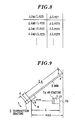
- a sine bar mechanism is adopted for this purpose. The principle thereof will be explained briefly with reference to FIG. 9, as follows.
- an LD 1 and a diffraction grating 2 form a Fabry-Perrot resonator.
- the resonance wavelength ⁇ M thereof in the equation (1) is expressed as follows.
- L A is the length of an arm (sine bar).
- ⁇ M - ⁇ b 2 x sin( ⁇ ) x ⁇ (L A /M) - (d/m) ⁇
- the wavelength shift can be set at zero regardless of the rotational angle 2 of the diffraction grating 2.
- the wavelength can be continuously changed without the mode hop.
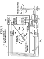
- FIG. 10 is an exemplary arrangement of a prior art external resonator type variable-wavelength LD light source.
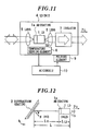
- an LD unit 4 includes, as shown in FIG. 11, a Fabry-Perrot type LD 1 coated on its one end face with an anti-reflection film (referred to as the AR coating, hereinafter) 1a, lenses 5 and 6, and an optical isolator 7. Further mounted to the LD unit 4 are a temperature detecting element 8 and a Peltier element 9, both of which are controlled with respect to temperature by a temperature adjustment circuit (referred to as the ATC circuit, hereinafter) 10.
- a temperature detecting element 8 and a Peltier element 9 both of which are controlled with respect to temperature by a temperature adjustment circuit (referred to as the ATC circuit, hereinafter) 10.
- the lens 5 comprises preferably a non-spherical lens or a combined or composite lens having a small liquid-level aberration.
- An LD end face 1b not having the AR coating 1a applied thereon as well as the diffraction grating 2 as an external reflecting mirror form an external resonator.
- the diffraction grating 2 is mounted to a rotary mechanism 11 and to one end of an arm (sine bar) 3, and the arm 3 abuts at the other end against an end face of a parallel moving mechanism 12.
- the parallel moving mechanism 12 which has the LD unit 4 fixedly mounted thereto, is arranged to be moved in parallel with directions shown by arrows X.
- a switch 13 Provided in the vicinity of the parallel moving mechanism 12 is a switch 13 as a position detecting means.
- a motor unit 14 as a driver unit includes a motor and an encoder, the motor being driven according to a pulse signal received from a control unit 15.
- the aforementioned LD unit 4, diffraction grating 2, rotary mechanism 11, arm 3, parallel moving mechanism 12, switch 13 and motor unit 14 are mounted on an optical system base 16.
- the LD 1 is driven by an LD driving current I LD received from an LD driver circuit 17.
- a beam splitter 18 is an optical device which acts to pass therethrough part of output light P O emitted from a variable-wavelength LD light source unit 19 as output light P O1 and to reflect part of the remaining output light P O as output light P O2 . Further, a PD unit 20 receives the reflected light P O2 , converts it to a voltage value V(P O2 ), and outputs the voltage value to the LD driver circuit 17.
- the switch 13 When the parallel moving mechanism 12 reaches a certain position, the switch 13 is turned ON. The position at which the switch 13 is turned ON, is assumed to be an origin position. When the switch 13 is turned ON, the switch outputs an origin detecting signal S G . The control unit 15, when recognizing the origin detecting signal S G , stops the output of the pulse signal to stop the motor. At the same time, the controller outputs a reset signal R e to reset the encoder of the motor unit 14. The then oscillation wavelength is measured by a wavelength meter and a measured value ⁇ O is assumed to be an origin wavelength ⁇ O . After this, the wavelength ⁇ O is set at the origin position.
- control unit 15 calculates a difference between a set wavelength ⁇ SET (referred to as the set wavelength, hereinafter) and the origin wavelength ⁇ O , and outputs to the motor of the motor unit 14 a pulse for causing the parallel moving mechanism 12 to be moved to a position corresponding to the set wavelength ⁇ SET .
- set wavelength referred to as the set wavelength, hereinafter
- the encoder of the motor unit 14 outputs always to the control unit 15 a signal S indicative of the movement amount of the parallel moving mechanism 12 moved by the motor, and the control unit 15 can recognize the current set wavelength based on the signal S.
- the aforementioned sine bar mechanism is employed so that the parallel movement of the parallel moving mechanism 12 in the arrow X direction causes change of the rotational angle 2 of the diffraction grating 2 and at the same time, as seen from the above equation (3), adjustment of the external resonator lengthL in response to a change in 2 realizes continuous variable wavelength without mode hop.
- ⁇ MA ⁇ M (T 0 )+ ⁇ M (I LD ) + ⁇ M (S)
- ⁇ M (T 0 ) is a change in the oscillation wavelength caused by thermal expansion involved by a temperature change in the entire light source unit
- ⁇ M (I LD ) is a change in the oscillation wavelength caused by a change in the LD driving current
- ⁇ M (S) is a shift of an actual oscillation wavelength from the set wavelength (encoder output value), caused by mechanical factors.
- Second one of the error causes is expressed by ⁇ M (T 0 ).
- the wavelength accuracy and wavelength reproducibility are guaranteed only at a constant temperature (e.g., 25oC), so that the thermal expansion and refractive index change caused by the temperature change of the entire light source unit cause change of "n" and "L” in the afore-mentioned equation (1), thus changing the oscillation wavelength ⁇ M .
- ⁇ M (T 0 ) ⁇ M /(n x L) ⁇ x ⁇ (n x L)
- variable-wavelength LD light source unit 19 mechanical parts are made of mainly invar material having a low thermal expansion coefficient, but the motor of the motor unit 14, diffraction grating 2, lenses 5 and 6, LD 1, etc. are made of stainless steel, glass, quartz, etc. respectively.
- Second one of the error causes comes from ⁇ M (I LD ) in the afore-mentioned equation (5), which results from a change in the LD driving current.
- ⁇ M (I LD ) ⁇ M (I LD )
- d ⁇ M /dI LD was about 2 pm/mA as an actually measured value of a DFB single laser.
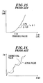
- Equation (1) is rewritten with use of parameters in FIG. 12, as follows.
- ⁇ M 2 x (n 0 x L 0 + n LD x L LD )/M
- n LD is the refractive index of the LD
- L 0 is "L - L LD " in FIG. 12
- L LD is the physical length of the LD.
- FIG. 14 A relationship between P 0 and I LD is as shown in FIG. 15, that is: ⁇ P 0 / ⁇ I LD ⁇ 0.1 mW/mA Where ⁇ P 0 denotes an optical output change. Since ⁇ P 0 ⁇ 3mW, ⁇ I LD ⁇ 30 mA.
- the set wavelength ⁇ SET corresponding to the output value of the encoder of the motor unit 14 and its actual oscillation wavelength vary proportionally in a 1:1 relationship; but they actually vary as shown by a solid line in FIG. 16.
- the present invention was developed in view of these problems. It is therefore an object of the present invention to provide an external resonator type variable-wavelength LD light source which can issue a constant optical output with a variable LD driving current, can ensure a wavelength reproducibility of 0.001 nm even when the LD driving current or operational temperature varies, can vary its oscillation wavelength continuously, and can be made low in cost and small in size.
- the external resonator type variable-wavelength LD light source comprises: a light source unit temperature detection member for detecting a temperature of an entire semiconductor laser light source unit; a storage unit for storing therein oscillation wavelength changes of the semiconductor laser light source unit on the basis of a change in a driving current to the semiconductor laser, of a change in the temperature of the entire semiconductor laser light source unit detected by the light source unit temperature detection member, and of a change in an encoder output value measured by an encoder; and a wavelength change compensation member for compensating a change of the oscillation wavelength of the semiconductor laser light source unit on the basis of the oscillation wavelength changes stored in the storage unit.
- the entire light source unit temperature detection member may comprise a temperature detecting element or any device so long as it has a function of detecting the temperature of the entire variable-wavelength LD light source unit.
- the storage unit may comprise an ordinary storage unit so long as it can store therein predetermined information.
- the oscillation wavelength change compensation member may comprise any device having any structure, so long as it has a function of eventually compensating a change in the oscillation wavelength of the variable-wavelength LD light source unit on the basis of the change of the oscillation wavelength stored in the storage unit.
- the invention is directed to the external resonator type variable-wavelength LD light source for compensating the change of the oscillation wavelength of the variable-wavelength LD light source unit by means of the oscillation wavelength change compensation member on the basis of the change of the oscillation wavelength of the variable-wavelength LD light source unit with respect to the change of the encoder output value; the external resonator type variable-wavelength LD light source can compensate errors of the change in the oscillation wavelength caused by the change in the LD driving current, the change in the oscillation wavelength caused by the change in the temperature of the entire light source unit, a difference between the set and actual wavelengths caused by mechanical factors to thereby ensure a wavelength reproducibility of 0.001 nm even when the LD driving current or operational temperature varies.
- the wavelength can be varied continuously, and the light source can be made low in cost and small in size.
- the external resonator type variable-wavelength LD light source comprises: a semiconductor laser unit including a semiconductor laser having a non-reflection film applied on its one end face, a temperature detecting element for measuring a temperature of the semiconductor laser and a Peltier element for changing the temperature of the semiconductor laser; a diffraction grating for forming a resonator together with the other end face of the semiconductor laser of the semiconductor laser unit having the non-reflection film not applied thereon; a sine bar mechanism having the diffraction grating mounted thereto for changing an incident angle of light emitted from the semiconductor laser to the diffraction grating; a parallel moving mechanism having the semiconductor laser unit mounted thereon and provided as contacted with the sine bar; a driver unit having a motor for finely driving the parallel moving mechanism and an encoder for measuring rotation of the motor; a position detecting member for detecting a position of the parallel moving mechanism; a temperature adjustment circuit for controlling a temperature of the semiconductor laser unit;
- the oscillation wavelength change compensation by the oscillation wavelength change compensation member may be carried out by controlling the ATC circuit under control of a controller to thereby change the temperature of the LD unit.
- the external resonator type variable-wavelength LD light source having such a member, since the oscillation wavelength change compensation member in the LD light source controls the ATC circuit under control of the controller to thereby change the temperature of the LD unit and to compensate the change of the oscillation wavelength of the variable-wavelength LD light source unit, the external resonator type variable-wavelength LD light source can compensate errors of the change in the oscillation wavelength caused by the change in the LD driving current, the change in the oscillation wavelength caused by the change in the temperature of the entire light source unit, and a difference between the set and actual wavelengths caused by mechanical factors to thereby ensure a wavelength reproducibility of, e.g., 0.001 nm even when the LD driving current or operational temperature varies, can vary the wavelength continuously, and can make its costs low and its size small.
- the oscillation wavelength change compensation by the oscillation wavelength change compensation member may be carried out by controlling driving of the motor under control of a controller to thereby move the parallel moving mechanism finely.
- the external resonator type variable-wavelength LD light source having such a member, since the oscillation wavelength change compensation member in the LD light source controls driving of the motor under control of a controller to thereby move the parallel moving mechanism finely and to compensate the change of the oscillation wavelength of the variable-wavelength LD light source unit, the external resonator type variable-wavelength LD light source can compensate errors of the change in the oscillation wavelength caused by the change in the LD driving current, the change in the oscillation wavelength caused by the change in the temperature of the entire light source unit, a difference between the set and actual wavelengths caused by mechanical factors, can ensure a wavelength reproducibility of 0.001 nm even when the LD driving current or operational temperature varies, can vary the wavelength continuously, and can make its costs low and its size small.
- the external resonator type variable-wavelength semiconductor laser light source further comprises a piezo element (referred to as the PZT, hereinafter) for finely moving the parallel moving mechanism by driving the motor, and in that the oscillation wavelength change compensation member controls driving of the motor under control of the controller to drive the PZT and to move the parallel moving mechanism finely.
- the PZT piezo element
- the external resonator type variable-wavelength LD light source having such a structure, since the LD light source further comprises the PZT for finely moving the parallel moving mechanism by driving the motor, and in that the oscillation wavelength change compensation member controls driving of the motor under control of the controller to drive the PZT and to move the parallel moving mechanism finely to thereby correct the change of the oscillation wavelength of the variable-wavelength LD light source unit, the external resonator type variable-wavelength LD light source can compensate, errors of the change in the oscillation wavelength caused by the change in the LD driving current, the change in the oscillation wavelength caused by the change in the temperature of the entire light source unit, a difference between the set and actual wavelengths caused by mechanical factors, can ensure a wavelength reproducibility of 0.001 nm even when the LD driving current or operational temperature varies, can vary the wavelength continuously, and can make its costs low and its size small.
- Embodiments of the external resonator type variable-wavelength LD light source in accordance with the present invention will be explained with reference to FIGS. 1 to 8.
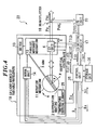
- FIG. 1 shows an arrangement of an external resonator type variable-wavelength LD light source 21 in accordance with the first embodiment of the present invention.
- parts having the same functions as those in FIG. 10 are denoted by the same reference numerals, and explanation therefor is omitted.
- a temperature detecting element 25 and a storage unit 26 are newly provided.
- the temperature detecting element 25 as a means for detecting a temperature of the entire light source unit detects a temperature of the optical system base 14, that is, a temperature of the entire variable-wavelength LD light source unit 19 as a detected temperature T O , and outputs the detected temperature to the control unit 15.
- the storage unit 26 stores therein the temperature T O of the variable-wavelengthLD light source unit 19, the LD driving current I LD and a wavelength compensation value based on the encoder output value S.
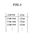
- the oscillation wavelength is measured under conditions of the constant temperature and constant LD driving current to prepare such a conversion table as shown in FIG. 3, and then stored in the storage unit 26 in FIG. 1.
- control unit 15 controls the motor of the motor unit 14 in such a manner that the encoder output S has a value corresponding to a set wavelength in the conversion table of FIG. 3, the error caused by the difference between the set and actual oscillation wavelengths resulting from the mechanical factors can be compensated.
- a wavelength setting resolution by the motor is 0.001 nm, then errors with respect to the oscillation wavelengths for the respective set wavelengths can be all suppressed to within 0.001 nm.
- the control unit15 reads the LD driving current LD driving current I LD and the temperature of T O of the entire variable-wavelength LD light source unit 19, and calculates a change ⁇ M in the oscillation wavelength caused by the change of the LD driving current and by the change of the temperature of the entire variable-wavelength LD light source unit 19.
- the change ⁇ M of the oscillation wavelength is a value to be compensated.
- the control unit 15 outputs the value ⁇ M to be compensated to the variable-wavelengthLD light source unit 19 to compensate the change of the oscillation wavelength.
- ⁇ M (d ⁇ M /dI LD ) x ⁇ I LD + (d ⁇ M /dT O ) x ⁇ T O
- ⁇ I LD is a change in the LD driving current
- ⁇ T O is a change in the temperature of the entire light source unit
- d ⁇ M /dI LD is a rate of change of oscillation wavelength caused by the change of the LD driving current
- d ⁇ M /dT O is a rate of change of the oscillation wavelength caused by the change of the temperature of the entire light source unit.
- a term (d ⁇ M /dI LD ) x ⁇ I LD in the equation (11) corresponds to the change of the oscillation wavelength caused by the change of the LD driving current
- a term (d ⁇ M /dT O ) x ⁇ T O corresponds to the change of the oscillation wavelength caused by the change of the temperature of the entire variable-wavelength LD light source unit 19.
- an oscillation wavelength change compensating means is formed for controlling the variable-wavelength LD light source unit 19 including the motor unit 14 under control of the control unit 15 on the basis of the stored information of the optical system base 14.
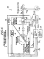
- FIG. 4 Shown in FIG. 4 is an arrangement of an external resonator type variable-wavelength LD light source unit 22 in accordance with the second embodiment of the present invention.
- parts having the same functions as those in the first embodiment of FIG. 1 are denoted by the same reference numerals, and explanation thereof is omitted.
- the control unit 15 reads the LD driving current LD driving current I LD and the temperature of T O of the entire variable-wavelength LD light source unit 19, and calculates a change ⁇ M in the oscillation wavelength.
- the controller calculates a value ⁇ T LD for compensation of the change ⁇ M of the oscillation wavelength and outputs V( ⁇ T LD ) corresponding to a voltage conversion thereof to the ATC circuit 10.
- ⁇ M (d ⁇ M /dI LD ) x ⁇ I LD + (n o x ⁇ x L O x ⁇ M /L) x ⁇ T O
- ⁇ is a thermal expansion coefficient of the optical system base.
- d ⁇ M /dI LD in the equation (12) is previously calculated by stopping the motor and measuring the LD driving current I LD and the oscillation wavelength ⁇ M with the constant LD driving current.
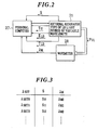
- n O x ⁇ x L O x ⁇ M /L corresponds to the term d ⁇ M /dI O in the equation (11), and is previously calculated, in such a measurement system as shown in FIG. 2, by stopping the motor and measuring the T O of the entire variable-wavelength LD light source unit 19 and the oscillation wavelength ⁇ M with the constant LD driving current.
- ⁇ M (n LD ) (dn LD /dT LD ) x ⁇ T LD x L LD x ⁇ M /(n O x L O + n LD x L LD )
- ⁇ n LD is a compensation of the refractive index of the LD
- ⁇ T LD is a compensation of the temperature of the LD
- dn LD /dT LD is a change in the refractive index of the LD caused by the change of the LD temperature.
- the temperature of the entire variable-wavelength LD light source unit 19 is made constant, the LD driving current is made constant and the motor of the motor unit 14 is stopped, ⁇ T LD and ⁇ M (n LD ) are actually measured to prepare such a conversion table as shown in FIG. 5, and stored in the storage unit 26 of FIG. 4, and then compensation is made based on the conversion table of FIG. 5.
- the change of the oscillation wavelength can be compensated with an accuracy of about 0.3 pm in accordance with the equation (14).
- an oscillation wavelength change compensating means is formed for controlling the ATC circuit 10 under control of the control unit 15 based on the stored information of the storage unit 26 to thereby change the temperature of the LD unit 4.
- FIG. 6 shows an arrangement of an external resonator type variable-wavelength LD light source unit 23 in the third embodiment of the present invention.
- parts having the same functions as those in the first embodiment of FIG. 1 are denoted by the same reference numerals, and explanation thereof is omitted.
- control unit 15 When assuming first that the errors caused by the differences between the set and actual oscillation wavelengths caused by the mechanical factors are already corrected in the conversion table of the storage unit 26, the control unit 15 reads the LD driving current LD driving current I LD and the temperature of T O of the entire variable-wavelength LD light source unit 19, and calculates a change ⁇ M in the oscillation wavelength.
- the parallel moving mechanism 12 is finely moved by the motor of the motor unit 14, and the motor is controlled so that the encoder output value becomes S+ ⁇ M /(d ⁇ M /dS) to compensate the change of the oscillation wavelength.
- d ⁇ M /dS is a rate of change of the oscillation wavelength caused by a change of the encoder output value.
- the compensation accuracy when the resolution of the wavelength setting by the motor of the motor unit 14 in FIG. 6 is 0.001 nm, the change of the oscillation wavelength can be compensated with an accuracy of 0.001 nm.
- an oscillation wavelength change compensating means is formed for controlling the parallel moving mechanism 12 based on the motor under control of the control unit 15 based on the stored information of the storage unit 26.
- FIG. 7 shows an arrangement of an external resonator type variable-wavelength LD light source unit 24 in accordance with the fourth embodiment of the present invention.
- parts having the same functions as those in the first embodiment of FIG. 1 are denoted by the same reference numerals, and explanation thereof is omitted.
- a PZT 29 is newly provided as shown in FIG. 7.
- the PZT 29 can finely move the parallel moving mechanism 12.
- control unit 15 When assuming first that the errors caused by the differences between the set and actual oscillation wavelengths caused by the mechanical factors are already corrected in the conversion table of the storage unit 26, the control unit 15 reads the LD driving current LD driving current I LD and the temperature of T O of the entire variable-wavelength LD light source unit 19, and calculates a change ⁇ M in the oscillation wavelength.
- control unit 15 calculates a value ⁇ L PZT for compensation of the change ⁇ M of the oscillation wavelength in accordance with the equation (8), controls the motor the motor unit 14, and finely moves the parallel moving mechanism 12 through the PZT 29 to compensate the change of the oscillation wavelength.
- ⁇ M is expressed by the equation (12) as in FIG. 6 of the third embodiment.
- ⁇ M (L PZT ) (n O x ⁇ L PZT ) x ⁇ M /( n O x L O + n LD x L LD ) where, ⁇ L PZT is a compensation of L O by PZT.
- the temperature of the entire variable-wavelength LD light source unit 19 is made constant and the LD driving current is made constant, ⁇ L PZT and ⁇ M (L PZT ) are actually measured to prepare such a conversion table as shown in FIG. 8, and stored in the storage unit 26 of FIG. 7, and then compensation is made based on the conversion table of FIG. 8.
- the change of the oscillation wavelength can be compensated with an accuracy of about 0.5 pm.
- an oscillation wavelength change compensating means is formed for controlling the parallel moving mechanism 12 based on the motor through the PZT 29 under control of the control unit 15 on the basis of the stored information of the storage unit 26.
- the switch has been used as the position detecting means in the foregoing respective embodiments, the present invention is not limited to the specific example, but any means may be uses so long as it has a position detecting function.
- the structures may be suitablymodified, as amatter of course.
- the external resonator type variable-wavelength LD light source of the invention can be operated with a constant optical output, can change the LD driving current, and can previously measure the change of the oscillation wavelength caused by the change of the LD driving current, the change of the oscillation wavelength caused by the change of the temperature of the entire light source unit, and the difference between the set and actual wavelengths caused by mechanical factors, and can store them in the form of corrected values to correspondingly correct the set wavelength even when the LD driving current or operational temperature varies, the light source can ensure a wavelength reproducibility of 0.001 nm, can vary the wavelength continuously, and can make its costs low and its size small.
- the external resonator type variable-wavelength LD light source having an oscillation wavelength change compensation member which controls the ATC circuit under control of the controller to thereby change the temperature of the LD unit and to compensate the change of the oscillation wavelength of the variable-wavelength LD light source unit
- the external resonator type variable-wavelength LD light source can compensate errors of the change in the oscillation wavelength caused by the change in the LD driving current, the change in the oscillation wavelength caused by the change in the temperature of the entire light source unit, and a difference between the set and actual wavelengths caused by mechanical factors to thereby ensure a wavelength reproducibility of, e.g., 0.001 nm even when the LD driving current or operational temperature varies, can vary the wavelength continuously, and can make its costs low and its size small.
- the external resonator type variable-wavelength LD light source having an oscillation wavelength change compensation member which controls driving of the motor under control of a controller to thereby move the parallel moving mechanism finely and to compensate the change of the oscillation wavelength of the variable-wavelength LD light source unit
- the external resonator type variable-wavelength LD light source can compensate errors of the change in the oscillation wavelength caused by the change in the LD driving current, the change in the oscillation wavelength caused by the change in the temperature of the entire light source unit, a difference between the set and actual wavelengths caused by mechanical factors, can ensure a wavelength reproducibility of 0.001 nm even when the LD driving current or operational temperature varies, can vary the wavelength continuously, and can make its costs low and its size small.
- the external resonator type variable-wavelength LD light source which further comprises the PZT for finely moving the parallel moving mechanism by driving the motor, and in that the oscillation wavelength change compensation member controls driving of the motor under control of the controller to drive the PZT and to move the parallel moving mechanism finely to thereby correct the change of the oscillation wavelength of the variable-wavelength LD light source unit
- the external resonator type variable-wavelength LD light source can compensate, errors of the change in the oscillation wavelength caused by the change in the LD driving current, the change in the oscillation wavelength caused by the change in the temperature of the entire light source unit, a difference between the set and actual wavelengths caused by mechanical factors, can ensure a wavelength reproducibility of 0.001 nm even when the LD driving current or operational temperature varies, can vary the wavelength continuously, and can make its costs low and its size small.
Landscapes
- Physics & Mathematics (AREA)
- Condensed Matter Physics & Semiconductors (AREA)
- General Physics & Mathematics (AREA)
- Electromagnetism (AREA)
- Optics & Photonics (AREA)
- Semiconductor Lasers (AREA)
Applications Claiming Priority (3)
| Application Number | Priority Date | Filing Date | Title |
|---|---|---|---|
| JP33852396A JP3218999B2 (ja) | 1996-12-18 | 1996-12-18 | 外部共振器型波長可変半導体レーザ光源 |
| JP338523/96 | 1996-12-18 | ||
| JP33852396 | 1996-12-18 |
Publications (3)
| Publication Number | Publication Date |
|---|---|
| EP0849846A2 true EP0849846A2 (fr) | 1998-06-24 |
| EP0849846A3 EP0849846A3 (fr) | 1999-06-30 |
| EP0849846B1 EP0849846B1 (fr) | 2001-09-19 |
Family
ID=18318971
Family Applications (1)
| Application Number | Title | Priority Date | Filing Date |
|---|---|---|---|
| EP97310127A Expired - Lifetime EP0849846B1 (fr) | 1996-12-18 | 1997-12-15 | Source laser à semi-conducteur du type à longueur d'onde accordable avec cavité externe |
Country Status (4)
| Country | Link |
|---|---|
| US (1) | US5982794A (fr) |
| EP (1) | EP0849846B1 (fr) |
| JP (1) | JP3218999B2 (fr) |
| DE (1) | DE69706819T2 (fr) |
Cited By (3)
| Publication number | Priority date | Publication date | Assignee | Title |
|---|---|---|---|---|
| EP1330000A1 (fr) * | 2002-12-06 | 2003-07-23 | Agilent Technologies Inc | Détermination du point de fonctionnement pour un laser à sélection de modes |
| WO2003005502A3 (fr) * | 2001-07-06 | 2004-03-25 | Intel Corp | Laser a cavite externe a regulation thermique selective |
| US7230959B2 (en) | 2002-02-22 | 2007-06-12 | Intel Corporation | Tunable laser with magnetically coupled filter |
Families Citing this family (18)
| Publication number | Priority date | Publication date | Assignee | Title |
|---|---|---|---|---|
| JPH11163450A (ja) * | 1997-11-28 | 1999-06-18 | Ando Electric Co Ltd | 波長可変光源 |
| CA2260630C (fr) * | 1998-01-30 | 2002-05-14 | Ando Electric Co., Ltd. | Appareil a source lumineuse variable en longueur d'onde |
| FR2775390B1 (fr) * | 1998-02-20 | 2000-05-05 | Photonetics | Source laser monomode continument accordable en longueur d'onde |
| JP3197869B2 (ja) * | 1998-03-31 | 2001-08-13 | アンリツ株式会社 | 波長可変レーザ光源装置 |
| US6856632B1 (en) * | 1999-09-20 | 2005-02-15 | Iolon, Inc. | Widely tunable laser |
| US6847661B2 (en) | 1999-09-20 | 2005-01-25 | Iolon, Inc. | Tunable laser with microactuator |
| US6903486B2 (en) | 1999-11-29 | 2005-06-07 | Iolon, Inc. | Balanced microdevice |
| WO2003067510A1 (fr) * | 2000-11-28 | 2003-08-14 | Ceyx Technologies, Inc. | Compensation de performance d'un laser en fonction de la temperature |
| DE60229560D1 (de) * | 2002-04-30 | 2008-12-04 | Agilent Technologies Inc | Wellenlängenabstimmbarer laser mit parameter korrektur |
| CA2475850A1 (fr) | 2003-01-08 | 2003-07-29 | Ceyx Technologies, Inc. | Appareil et procede pour mesurer des signaux laser dynamiques |
| JP2006086430A (ja) * | 2004-09-17 | 2006-03-30 | Yokogawa Electric Corp | 波長可変光源 |
| JP2006171380A (ja) * | 2004-12-16 | 2006-06-29 | Sony Corp | ホログラム記録再生装置及びホログラム記録再生方法 |
| JP4081095B2 (ja) * | 2005-03-16 | 2008-04-23 | 日本電信電話株式会社 | 光通信用光源部に格納する光出力波長特性及び光出力電力特性の測定点の選定方法 |
| CA2560143C (fr) | 2005-03-16 | 2009-06-23 | Nippon Telegraph And Telephone Corporation | Source lumineuse de communication optique et methode de controle par surveillance de longueur d'onde |
| JP2006324561A (ja) * | 2005-05-20 | 2006-11-30 | Sony Corp | レーザ装置および回折格子の駆動方法 |
| JP5536401B2 (ja) | 2008-10-16 | 2014-07-02 | ギガフォトン株式会社 | レーザ装置および極端紫外光光源装置 |
| IT201900002013A1 (it) * | 2019-02-12 | 2020-08-12 | Laboratorio Europeo Di Spettroscopie Non Lineari Lens | Dispositivo laser a cavita' esterna, sistema e procedimento corrispondenti |
| DE112021007338T5 (de) * | 2021-03-23 | 2024-01-04 | Mitsubishi Electric Corporation | Lasersystem |
Family Cites Families (17)
| Publication number | Priority date | Publication date | Assignee | Title |
|---|---|---|---|---|
| BG47632A1 (en) * | 1987-11-30 | 1990-08-15 | Univ Sofijski | Method and device for determining moment of switching of system for active thermostabilizing of resonator lenght in frequency stabilized lasers |
| JPH01251681A (ja) * | 1988-03-25 | 1989-10-06 | Topcon Corp | 半導体レーザーの発振周波数・発振出力安定化装置 |
| JP3407893B2 (ja) * | 1991-05-27 | 2003-05-19 | パイオニア株式会社 | 半導体レーザ制御装置 |
| EP0529731B1 (fr) * | 1991-08-30 | 1995-11-08 | Koninklijke Philips Electronics N.V. | Oscillateur à laser à accord continu |
| US5414727A (en) * | 1991-09-30 | 1995-05-09 | Honeywell Inc. | Active current control apparatus |
| EP0618653B1 (fr) * | 1993-03-30 | 1997-07-16 | Nec Corporation | Méthode de stabilisation de la fréquence d'un laser à semi-conducteur et source de lumière stabilisée en fréquence |
| JPH0799359A (ja) * | 1993-09-27 | 1995-04-11 | Ando Electric Co Ltd | 外部共振器型周波数可変半導体レーザ光源 |
| JP3272837B2 (ja) * | 1993-11-08 | 2002-04-08 | レーザー濃縮技術研究組合 | レ−ザ発振装置 |
| JPH07164673A (ja) * | 1993-12-13 | 1995-06-27 | Minolta Co Ltd | レーザ駆動装置 |
| JPH07240558A (ja) * | 1994-02-28 | 1995-09-12 | Ando Electric Co Ltd | 波長可変半導体レーザ光源 |
| US5579327A (en) * | 1994-06-06 | 1996-11-26 | Anritsu Corporation | External-cavity tunable wavelength light source using semiconductor laser having phase adjustment area |
| US5521738A (en) * | 1994-06-30 | 1996-05-28 | At&T Corp. | Data encoded optical pulse generator |
| US5706301A (en) * | 1995-08-16 | 1998-01-06 | Telefonaktiebolaget L M Ericsson | Laser wavelength control system |
| US5604758A (en) * | 1995-09-08 | 1997-02-18 | Xerox Corporation | Microprocessor controlled thermoelectric cooler and laser power controller |
| US5844928A (en) * | 1996-02-27 | 1998-12-01 | Lucent Technologies, Inc. | Laser driver with temperature sensor on an integrated circuit |
| DE19620594A1 (de) * | 1996-05-22 | 1997-11-27 | Sel Alcatel Ag | Resonator für elektromagnetische Wellen mit einer Stabilisierungseinrichtung und Verfahren zum Stabilisieren der Resonatorlänge |
| JP2871623B2 (ja) * | 1996-07-11 | 1999-03-17 | 日本電気株式会社 | 半導体レーザ装置 |
-
1996
- 1996-12-18 JP JP33852396A patent/JP3218999B2/ja not_active Expired - Fee Related
-
1997
- 1997-12-15 EP EP97310127A patent/EP0849846B1/fr not_active Expired - Lifetime
- 1997-12-15 DE DE69706819T patent/DE69706819T2/de not_active Expired - Fee Related
- 1997-12-17 US US08/992,717 patent/US5982794A/en not_active Expired - Fee Related
Cited By (5)
| Publication number | Priority date | Publication date | Assignee | Title |
|---|---|---|---|---|
| WO2003005502A3 (fr) * | 2001-07-06 | 2004-03-25 | Intel Corp | Laser a cavite externe a regulation thermique selective |
| US6724797B2 (en) | 2001-07-06 | 2004-04-20 | Intel Corporation | External cavity laser with selective thermal control |
| US7230959B2 (en) | 2002-02-22 | 2007-06-12 | Intel Corporation | Tunable laser with magnetically coupled filter |
| EP1330000A1 (fr) * | 2002-12-06 | 2003-07-23 | Agilent Technologies Inc | Détermination du point de fonctionnement pour un laser à sélection de modes |
| US6901094B2 (en) | 2002-12-06 | 2005-05-31 | Agilent Technologies, Inc. | Operating point determination for mode-selection laser |
Also Published As
| Publication number | Publication date |
|---|---|
| JP3218999B2 (ja) | 2001-10-15 |
| JPH10178240A (ja) | 1998-06-30 |
| EP0849846A3 (fr) | 1999-06-30 |
| EP0849846B1 (fr) | 2001-09-19 |
| US5982794A (en) | 1999-11-09 |
| DE69706819T2 (de) | 2002-04-11 |
| DE69706819D1 (de) | 2001-10-25 |
Similar Documents
| Publication | Publication Date | Title |
|---|---|---|
| US5982794A (en) | External resonator type of variable-wavelength semiconductor laser light source | |
| EP0867989B1 (fr) | Source de lumière à semi-conducteur à longueur d'onde accordable | |
| US6304586B1 (en) | Method and apparatus for modulating a tunable laser | |
| US6804278B2 (en) | Evaluation and adjustment of laser losses according to voltage across gain medium | |
| EP0693231B1 (fr) | Systeme d'accord pour laser a diode a cavite externe | |
| US5387974A (en) | Laser apparatus including Fabry-perot wavelength detector with temperature and wavelength compensation | |
| JPH10341057A (ja) | 外部共振器型波長可変半導体レーザー光源およびその波長可変方法 | |
| US20070195328A1 (en) | Wavelength measurement method based on combination of two signals in quadrature | |
| JP2002374034A (ja) | 可変波長光源装置 | |
| US5548609A (en) | External resonator type wavelength-variable semiconductor laser light source | |
| US20070127539A1 (en) | Narrow band laser with wavelength stability | |
| US6850545B2 (en) | Wavelength tunable light source | |
| JPH0897516A (ja) | 波長安定化外部共振器型ld光源 | |
| JP3602664B2 (ja) | 波長可変レーザ光発生方法およびその装置 | |
| JPH1168248A (ja) | 外部共振器型波長可変半導体レーザ光源 | |
| EP1671403B1 (fr) | Unite de controle de laser angulaire | |
| JPH09260792A (ja) | 外部共振器型波長可変ld光源 | |
| JPH09129982A (ja) | 外部共振器型ld光源 | |
| JPH10107370A (ja) | 外部共振器型波長可変半導体レーザ光源の位相調整装置 | |
| JPH11220198A (ja) | 波長可変光源装置 | |
| JP2823870B2 (ja) | 半導体レーザのスペクトル線幅狭窄化装置 | |
| JPH0945983A (ja) | 波長可変半導体レーザ | |
| JPH11274643A (ja) | 可変波長半導体レーザ光源 | |
| JPH09270557A (ja) | レーザ光発生装置 | |
| JPH03150889A (ja) | 波長可変型レーザ装置 |
Legal Events
| Date | Code | Title | Description |
|---|---|---|---|
| PUAI | Public reference made under article 153(3) epc to a published international application that has entered the european phase |
Free format text: ORIGINAL CODE: 0009012 |
|
| AK | Designated contracting states |
Kind code of ref document: A2 Designated state(s): DE FR GB |
|
| AX | Request for extension of the european patent |
Free format text: AL;LT;LV;MK;RO;SI |
|
| PUAL | Search report despatched |
Free format text: ORIGINAL CODE: 0009013 |
|
| AK | Designated contracting states |
Kind code of ref document: A3 Designated state(s): AT BE CH DE DK ES FI FR GB GR IE IT LI LU MC NL PT SE |
|
| AX | Request for extension of the european patent |
Free format text: AL;LT;LV;MK;RO;SI |
|
| RIC1 | Information provided on ipc code assigned before grant |
Free format text: 6H 01S 3/085 A, 6H 01S 3/1055 B, 6H 01S 3/133 B |
|
| 17P | Request for examination filed |
Effective date: 19990625 |
|
| AKX | Designation fees paid |
Free format text: DE FR GB |
|
| 17Q | First examination report despatched |
Effective date: 20000619 |
|
| RIC1 | Information provided on ipc code assigned before grant |
Free format text: 7H 01S 5/14 A, 7H 01S 3/1055 B, 7H 01S 5/068 B |
|
| RIC1 | Information provided on ipc code assigned before grant |
Free format text: 7H 01S 5/14 A, 7H 01S 3/1055 B, 7H 01S 5/068 B |
|
| GRAG | Despatch of communication of intention to grant |
Free format text: ORIGINAL CODE: EPIDOS AGRA |
|
| GRAG | Despatch of communication of intention to grant |
Free format text: ORIGINAL CODE: EPIDOS AGRA |
|
| GRAH | Despatch of communication of intention to grant a patent |
Free format text: ORIGINAL CODE: EPIDOS IGRA |
|
| GRAH | Despatch of communication of intention to grant a patent |
Free format text: ORIGINAL CODE: EPIDOS IGRA |
|
| GRAA | (expected) grant |
Free format text: ORIGINAL CODE: 0009210 |
|
| AK | Designated contracting states |
Kind code of ref document: B1 Designated state(s): DE FR GB |
|
| REF | Corresponds to: |
Ref document number: 69706819 Country of ref document: DE Date of ref document: 20011025 |
|
| PGFP | Annual fee paid to national office [announced via postgrant information from national office to epo] |
Ref country code: FR Payment date: 20011212 Year of fee payment: 5 |
|
| PGFP | Annual fee paid to national office [announced via postgrant information from national office to epo] |
Ref country code: GB Payment date: 20011219 Year of fee payment: 5 |
|
| REG | Reference to a national code |
Ref country code: GB Ref legal event code: IF02 |
|
| PGFP | Annual fee paid to national office [announced via postgrant information from national office to epo] |
Ref country code: DE Payment date: 20020109 Year of fee payment: 5 |
|
| ET | Fr: translation filed | ||
| PLBE | No opposition filed within time limit |
Free format text: ORIGINAL CODE: 0009261 |
|
| STAA | Information on the status of an ep patent application or granted ep patent |
Free format text: STATUS: NO OPPOSITION FILED WITHIN TIME LIMIT |
|
| 26N | No opposition filed | ||
| PG25 | Lapsed in a contracting state [announced via postgrant information from national office to epo] |
Ref country code: GB Free format text: LAPSE BECAUSE OF NON-PAYMENT OF DUE FEES Effective date: 20021215 |
|
| PG25 | Lapsed in a contracting state [announced via postgrant information from national office to epo] |
Ref country code: DE Free format text: LAPSE BECAUSE OF NON-PAYMENT OF DUE FEES Effective date: 20030701 |
|
| GBPC | Gb: european patent ceased through non-payment of renewal fee |
Effective date: 20021215 |
|
| PG25 | Lapsed in a contracting state [announced via postgrant information from national office to epo] |
Ref country code: FR Free format text: LAPSE BECAUSE OF NON-PAYMENT OF DUE FEES Effective date: 20030901 |
|
| REG | Reference to a national code |
Ref country code: FR Ref legal event code: ST |