EP0852458A1 - Dispositif d'alimentation en composants electroniques - Google Patents
Dispositif d'alimentation en composants electroniques Download PDFInfo
- Publication number
- EP0852458A1 EP0852458A1 EP97927439A EP97927439A EP0852458A1 EP 0852458 A1 EP0852458 A1 EP 0852458A1 EP 97927439 A EP97927439 A EP 97927439A EP 97927439 A EP97927439 A EP 97927439A EP 0852458 A1 EP0852458 A1 EP 0852458A1
- Authority
- EP
- European Patent Office
- Prior art keywords
- electronic component
- electronic components
- forefront
- chute
- tilted
- Prior art date
- Legal status (The legal status is an assumption and is not a legal conclusion. Google has not performed a legal analysis and makes no representation as to the accuracy of the status listed.)
- Granted
Links
Images

Classifications
-
- H—ELECTRICITY
- H05—ELECTRIC TECHNIQUES NOT OTHERWISE PROVIDED FOR
- H05K—PRINTED CIRCUITS; CASINGS OR CONSTRUCTIONAL DETAILS OF ELECTRIC APPARATUS; MANUFACTURE OF ASSEMBLAGES OF ELECTRICAL COMPONENTS
- H05K13/00—Apparatus or processes specially adapted for manufacturing or adjusting assemblages of electric components
- H05K13/02—Feeding of components
- H05K13/021—Loading or unloading of containers
-
- H—ELECTRICITY
- H05—ELECTRIC TECHNIQUES NOT OTHERWISE PROVIDED FOR
- H05K—PRINTED CIRCUITS; CASINGS OR CONSTRUCTIONAL DETAILS OF ELECTRIC APPARATUS; MANUFACTURE OF ASSEMBLAGES OF ELECTRICAL COMPONENTS
- H05K13/00—Apparatus or processes specially adapted for manufacturing or adjusting assemblages of electric components
- H05K13/02—Feeding of components
-
- H—ELECTRICITY
- H05—ELECTRIC TECHNIQUES NOT OTHERWISE PROVIDED FOR
- H05K—PRINTED CIRCUITS; CASINGS OR CONSTRUCTIONAL DETAILS OF ELECTRIC APPARATUS; MANUFACTURE OF ASSEMBLAGES OF ELECTRICAL COMPONENTS
- H05K13/00—Apparatus or processes specially adapted for manufacturing or adjusting assemblages of electric components
- H05K13/04—Mounting of components, e.g. of leadless components
- H05K13/043—Feeding one by one by other means than belts
- H05K13/0434—Feeding one by one by other means than belts with containers
-
- Y—GENERAL TAGGING OF NEW TECHNOLOGICAL DEVELOPMENTS; GENERAL TAGGING OF CROSS-SECTIONAL TECHNOLOGIES SPANNING OVER SEVERAL SECTIONS OF THE IPC; TECHNICAL SUBJECTS COVERED BY FORMER USPC CROSS-REFERENCE ART COLLECTIONS [XRACs] AND DIGESTS
- Y10—TECHNICAL SUBJECTS COVERED BY FORMER USPC
- Y10T—TECHNICAL SUBJECTS COVERED BY FORMER US CLASSIFICATION
- Y10T29/00—Metal working
- Y10T29/53—Means to assemble or disassemble
- Y10T29/53478—Means to assemble or disassemble with magazine supply
Definitions
- the present invention relates to an electronic component feeding apparatus for feeding electronic components one by one which are stored in sticks in an automatic mounting operation of electronic components.
- the common electronic component feeding apparatus of such type comprises a holder 3 for holding a group of sticks 1, each stick storing a row of electronic components, a tilted chute 4 having a separating means 6 at the front end thereof for separating the forefront electronic component 2 from another, and a swinging means 7 for holding and moving the forefront electronic component 2 to a horizontal position 35.
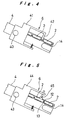
- the separating means 6 may, for example, comprise a pivotal block 41 having a separating pin 42 and being arranged movable about a pivot 40 located at the front end of the tilted chute 4, and a shutter 14 which opens and closes, as shown in Fig. 4.
- the electronic components 2 joined to one another are downwardly released from the stick 1 and guided by the tilted chute 4 to slide down to the front end of the chute 4 due to its own weight.
- the separating means 6 rotates the pivotal block 41 to cause the separating pin 42 to be inserted between the forefront and the succeeding electronic components 2 to separate them.
- the shutter 14 at the front end of the tilted chute 4 is then opened to transfer only the separated electronic component 2 to the swinging means 7.
- separating pin 42 fails to be inserted between the two adjacent electronic components 2 depending on configuration of the interface between the components.
- another example of the separating means 6 which has been employed includes a stopper 45 which holds the second electronic component 2 from above while permitting the first one to run through the opened shutter 14 at the front end of the tilted chute 4 to the swinging means 7, as shown in Fig. 5.
- the electronic component feeding apparatus has a holder for holding sticks, each stick storing a plurality of electronic components joined to each other, a tilted chute mounted to be sloped for allowing the electronic components to run down from the stick and provided with a separating means at a front end thereof for separating a forefront electronic component from the others, and a swinging means for holding and moving the forefront electronic component to a horizontal position, and is characterized in that the separating means comprises a- step which is dropped in level at a front end of the tilted chute for receiving the forefront electronic component and an arm for holding down the succeeding electronic component from above and for moving the same backward along the tilted chute.
- the two burrs are easily separated because the forefront electronic component is brought to a position lower than the succeeding electronic component at the step on the tilted chute, whereby the burrs between the adjacent electronic components are disengaged, separating the forefront electronic component. If the burr of the leading electronic component overlaps the burr of the succeeding electronic component when they are sliding down on the tilted chute, the succeeding electronic component is held down from above and forcibly moved backward on the tilted chute.
- the present invention can be implemented by a conventional electronic component feeding apparatus with a stick feeder which is simply modified with its tilted chute having a step and its separating means having a sliding mechanism.
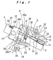
- Fig. 1 is a side view of a separating means according to one embodiment of the present invention
- Fig. 2 is a schematic view showing the overall arrangement of an electronic component feeding apparatus of the present invention
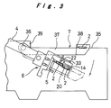
- Fig. 3 is a side view of a swinging means according to one embodiment of the present invention
- Fig. 4 is a side view of a conventional separating means
- Fig. 5 is a side view of another conventional separating means.
- An electronic component feeding apparatus of the present invention comprises, as shown in Figs. 1 to 3, a holder 3 for holding a group of sticks 1, each stick storing a row of electronic components 2, a tilted chute 4 given a slope allowing the electronic components 2 to slide down from the stick 1 and having a separating means 5 at its front end 5 for separating the electronic component 2 at the head from another, and a swinging means 7 for holding and moving the forefront electronic component 2 to a horizontal feeding location 35.
- the separating means 6 comprises, as best shown in Fig. 1, a step 20 located at the front end 5 of the chute 4, a shutter 14 provided at the front end of the step 20 and driven by an opening/closing means 33 to open and close for letting the forefront electronic component 2 to slide down toward the swinging means 7, a pivotal block 15 supported about a pivot 17 located on the front end 5 of the chute 4 for turning movement in the direction of b, a slide block 21 supported by a pair of guide pins 18a and 18b on the pivotal block 15 for sliding movement along the direction c, a drive pin 19 mounted to actuate the turning movement of the pivotal block 15 and the sliding movement of the slide block 21, and a drive unit (not shown) for driving the drive pin 19 linking with the action of the shutter 14.
- the step 20 disposed at the front end 5 of the chute 4 is a tilted portion which is dropped in level, and has a length slightly greater than that of the electronic component 2. Its level is lowered from the front end 5 of the chute 4 to have a depth being substantially one half of the height of the electronic component 2, so that it can accept only one electronic component at a time.
- the pivotal block 15 includes a hole in which the pivot 17 is supportingly fitted, a pivotal operating part 26 for direct contact with the drive pin 19, the pair of upper and lower guide pins 18a and 18b supporting the slide block 21 in such a way that the slide block 21 can reciprocate only along the direction of c which is parallel to a straight line across the pivot 17 but is inhibited to pivot with respect to the pivotal block 15, and a spring 27 fixedly mounted at one end to an anchor portion 29 of the pivotal block 15 and at the other end to an anchor portion 30 of the tilted chute 4 for restoring the rotated pivotal block 15.
- the slide block 21 comprises an arm 22 for holding down the upper side of the succeeding electronic component 2 through a friction member 23, a slider operating part 24 for direct contact with the drive pin 19, a pair of upper and lower guide holes 25a and 25b for respectively receiving the pair of guide pins 18a and 18b so that the slide block 21 can reciprocate along the direction of c which is parallel to the straight line across the pivot 17, and a spring 28 fixedly mounted at one end to an anchor portion 31 of the slide block 21 and at the other end to an anchor portion 32 of the pivotal block 15 for restoring the slide block 21 to its initial position.
- the swinging means 7 comprises, as best shown in Fig. 3, a swing arm 37 mounted for pivotal movement about a pivot 36 located near the front end 5 of the tilted chute 4, a component holder 38 mounted to the distal end of the swing arm 37 for forward and backward movements between an extension of the step 20 and a horizontal feeding position 35 when receiving the electronic component 2, and a drive unit 39 for driving the swing arm 37 linking with the opening and closing action of the shutter 14.
- the drive pin 19 pushes the pivotal operating part 26 of the pivotal block 15 against the yielding force of the spring 27 to lift up the arm 22, which allows the electronic components 2 joined one another to slide downwardly to the front end 5 of the tilted chute 4, and the forefront electronic component 2 is guided into the step 20.
- the drive pin 19 is detached from the pivotal operating part 26, the arm 22 is actuated by the resiling force of the spring 27 to hold down the succeeding electronic component 2 with the friction member 23 at its distal end.
- the forefront electronic component 2 is slid down with the succeeding electronic component 2 having the burr 13 at its front end overlapping the burr 12 at the rear end of the forefront electronic component 2, the forefront electronic component 2 is led into the step 20 being dropped in level, thus causing the burrs 12 and 13 to be disengaged, or the forefront electronic component 2 is caught by a step wall 34 and kept to be in the step 20, causing the succeeding electronic component 2 to be separated therefrom. Also, in case that the burr 12 at the rear end of the forefront electronic component 2 overlaps the burr 13 at the leading end of the succeeding electronic component 2, the forefront electronic component 2 is tilted by its own weight and caught by the step wall 34, thus being separated from the succeeding electronic component 2.
- the electronic components feeding apparatus of the present invention permits a number of electronic components to be separated from each other and fed one by one regardless of the configuration at the joining ends of the electronic components as well as the presence of burrs developed during a molding process of the electronic components, and is thus favorably applied to the implementation of stick supply in automatic mounting operation of the electronic components.
Landscapes
- Engineering & Computer Science (AREA)
- Manufacturing & Machinery (AREA)
- Microelectronics & Electronic Packaging (AREA)
- Feeding Of Articles To Conveyors (AREA)
- Branching, Merging, And Special Transfer Between Conveyors (AREA)
- Supply And Installment Of Electrical Components (AREA)
- Automatic Assembly (AREA)
Applications Claiming Priority (4)
| Application Number | Priority Date | Filing Date | Title |
|---|---|---|---|
| JP163180/96 | 1996-06-24 | ||
| JP8163180A JPH1013089A (ja) | 1996-06-24 | 1996-06-24 | 電子部品供給装置 |
| JP16318096 | 1996-06-24 | ||
| PCT/JP1997/002168 WO1997050284A1 (fr) | 1996-06-24 | 1997-06-23 | Dispositif d'alimentation en composants electroniques |
Publications (3)
| Publication Number | Publication Date |
|---|---|
| EP0852458A1 true EP0852458A1 (fr) | 1998-07-08 |
| EP0852458A4 EP0852458A4 (fr) | 2000-10-18 |
| EP0852458B1 EP0852458B1 (fr) | 2005-05-04 |
Family
ID=15768774
Family Applications (1)
| Application Number | Title | Priority Date | Filing Date |
|---|---|---|---|
| EP97927439A Expired - Lifetime EP0852458B1 (fr) | 1996-06-24 | 1997-06-23 | Dispositif d'alimentation en composants electroniques |
Country Status (7)
| Country | Link |
|---|---|
| US (1) | US6132167A (fr) |
| EP (1) | EP0852458B1 (fr) |
| JP (1) | JPH1013089A (fr) |
| KR (1) | KR19990036413A (fr) |
| CN (1) | CN1110990C (fr) |
| DE (1) | DE69733188T2 (fr) |
| WO (1) | WO1997050284A1 (fr) |
Cited By (1)
| Publication number | Priority date | Publication date | Assignee | Title |
|---|---|---|---|---|
| US10455749B2 (en) | 2017-02-03 | 2019-10-22 | Fanuc Corporation | Parts supply device and parts supply robot having the same |
Families Citing this family (6)
| Publication number | Priority date | Publication date | Assignee | Title |
|---|---|---|---|---|
| US6264415B1 (en) * | 1999-09-30 | 2001-07-24 | Advanced Micro Devices, Inc. | Mechanism for accurately transferring a predetermined number of integrated circuit packages from tube to tube |
| KR100932730B1 (ko) * | 2007-11-20 | 2009-12-21 | 김동석 | 전자부품 급송테이프 연결용 클립, 이를 구비한 클립 리본및 이를 이용한 전자부품 급송테이프 연결기구 |
| JP5772461B2 (ja) * | 2011-09-30 | 2015-09-02 | 富士通株式会社 | 部品搬送装置及び部品搬送方法 |
| US9975708B2 (en) * | 2016-03-16 | 2018-05-22 | Texas Instruments Incorporated | Transfer track stopper for packaged integrated circuits |
| JP6901931B2 (ja) * | 2017-02-24 | 2021-07-14 | 太陽誘電株式会社 | テーピング装置 |
| JP6467695B1 (ja) * | 2018-10-02 | 2019-02-13 | 株式会社エナデック | ワーク供給装置 |
Family Cites Families (12)
| Publication number | Priority date | Publication date | Assignee | Title |
|---|---|---|---|---|
| JPS5986297A (ja) * | 1982-11-09 | 1984-05-18 | 日本電気株式会社 | ワ−ク供給シユ−ト |
| JPS59129681A (ja) * | 1983-01-17 | 1984-07-26 | 松下電器産業株式会社 | 部品供給装置 |
| JPS60197518A (ja) * | 1984-03-15 | 1985-10-07 | Alps Electric Co Ltd | 部品供給装置 |
| US4599026A (en) * | 1985-02-26 | 1986-07-08 | Amp Incorporated | Apparatus for providing a continuous supply of workpieces |
| KR900001090B1 (ko) * | 1985-07-17 | 1990-02-26 | 후지쓰가부시끼가이샤 | 전자부품 삽입장치 |
| DE3704750A1 (de) * | 1985-11-11 | 1988-08-25 | Heigl Helmuth | Vereinzelungsvorrichtung |
| JP2523624B2 (ja) * | 1987-04-28 | 1996-08-14 | 松下電器産業株式会社 | 電子部品供給方法およびその装置 |
| JPH04223400A (ja) * | 1990-12-25 | 1992-08-13 | Hitachi Electron Eng Co Ltd | Icデバイスの移し替え装置 |
| JPH05198969A (ja) * | 1992-01-21 | 1993-08-06 | Citizen Watch Co Ltd | 電子部品供給装置 |
| JPH0652193A (ja) * | 1992-08-03 | 1994-02-25 | Omron Corp | 注文登録システム |
| JPH0652193U (ja) * | 1992-12-24 | 1994-07-15 | 栄幸精機株式会社 | プリント基板に対する異形電子部品挿入機への異形電子部品供給装置 |
| US5503299A (en) * | 1994-07-18 | 1996-04-02 | Advantek, Inc. | Inertial parts feeding apparatus and method |
-
1996
- 1996-06-24 JP JP8163180A patent/JPH1013089A/ja active Pending
-
1997
- 1997-06-23 EP EP97927439A patent/EP0852458B1/fr not_active Expired - Lifetime
- 1997-06-23 DE DE69733188T patent/DE69733188T2/de not_active Expired - Fee Related
- 1997-06-23 WO PCT/JP1997/002168 patent/WO1997050284A1/fr not_active Ceased
- 1997-06-23 KR KR1019980701082A patent/KR19990036413A/ko not_active Ceased
- 1997-06-23 CN CN97190755A patent/CN1110990C/zh not_active Expired - Fee Related
- 1997-06-26 US US09/029,102 patent/US6132167A/en not_active Expired - Fee Related
Cited By (1)
| Publication number | Priority date | Publication date | Assignee | Title |
|---|---|---|---|---|
| US10455749B2 (en) | 2017-02-03 | 2019-10-22 | Fanuc Corporation | Parts supply device and parts supply robot having the same |
Also Published As
| Publication number | Publication date |
|---|---|
| KR19990036413A (ko) | 1999-05-25 |
| EP0852458B1 (fr) | 2005-05-04 |
| JPH1013089A (ja) | 1998-01-16 |
| EP0852458A4 (fr) | 2000-10-18 |
| DE69733188T2 (de) | 2006-02-02 |
| CN1110990C (zh) | 2003-06-04 |
| DE69733188D1 (de) | 2005-06-09 |
| CN1196872A (zh) | 1998-10-21 |
| WO1997050284A1 (fr) | 1997-12-31 |
| US6132167A (en) | 2000-10-17 |
Similar Documents
| Publication | Publication Date | Title |
|---|---|---|
| US6671946B1 (en) | Component mounting machine | |
| EP0852458B1 (fr) | Dispositif d'alimentation en composants electroniques | |
| US6254332B1 (en) | Nut feeder for feeding nuts for resistance welding | |
| CN115108212A (zh) | 挂入机构、进仓装置、入库设备以及带式仓储系统 | |
| JP4435317B2 (ja) | Oリング組付装置及び組付方法 | |
| KR100520997B1 (ko) | 사출 성형 렌즈 처리 장치 | |
| JPH0645406B2 (ja) | Icテスターのためにスリーブを積み降ろしするための装置 | |
| EP0957050B1 (fr) | Dispositif de transport de composants | |
| US6332529B1 (en) | Component conveying device | |
| KR860001939B1 (ko) | 양쪽 방향으로 개방될 수 있는 슬라이드 파스너를 제조하는 장치 | |
| JPH1074777A (ja) | リードフレーム搬送方法及び搬送装置 | |
| JP3491517B2 (ja) | 電子部品実装機 | |
| US6733228B2 (en) | Apparatus for transporting parts | |
| JP3750377B2 (ja) | 部品搬送装置 | |
| JP3094197B2 (ja) | スライダーの引手取付装置 | |
| JPH09194028A (ja) | 部品供給装置 | |
| JP7432720B2 (ja) | 部品保持具、および装着方法 | |
| JP2847030B2 (ja) | 部品分離装置 | |
| JPH0671446B2 (ja) | スライドフアスナ−製造装置 | |
| JPH0145756B2 (fr) | ||
| JPS631620A (ja) | コイルばねの分離装置 | |
| KR970004833B1 (ko) | 테스터 핸들러의 슬리브 2단 업/다운 장치 | |
| JP2848104B2 (ja) | 部品供給装置 | |
| JPS6255718B2 (fr) | ||
| EP0257160A1 (fr) | Boucle pour cuir ou tissu et machine automatique pour la pose de telles boucles |
Legal Events
| Date | Code | Title | Description |
|---|---|---|---|
| PUAI | Public reference made under article 153(3) epc to a published international application that has entered the european phase |
Free format text: ORIGINAL CODE: 0009012 |
|
| 17P | Request for examination filed |
Effective date: 19980313 |
|
| AK | Designated contracting states |
Kind code of ref document: A1 Designated state(s): DE FR GB |
|
| A4 | Supplementary search report drawn up and despatched |
Effective date: 20000901 |
|
| AK | Designated contracting states |
Kind code of ref document: A4 Designated state(s): DE FR GB |
|
| 17Q | First examination report despatched |
Effective date: 20030923 |
|
| GRAP | Despatch of communication of intention to grant a patent |
Free format text: ORIGINAL CODE: EPIDOSNIGR1 |
|
| GRAS | Grant fee paid |
Free format text: ORIGINAL CODE: EPIDOSNIGR3 |
|
| GRAA | (expected) grant |
Free format text: ORIGINAL CODE: 0009210 |
|
| AK | Designated contracting states |
Kind code of ref document: B1 Designated state(s): DE FR GB |
|
| REG | Reference to a national code |
Ref country code: GB Ref legal event code: FG4D |
|
| REF | Corresponds to: |
Ref document number: 69733188 Country of ref document: DE Date of ref document: 20050609 Kind code of ref document: P |
|
| ET | Fr: translation filed | ||
| PLBE | No opposition filed within time limit |
Free format text: ORIGINAL CODE: 0009261 |
|
| STAA | Information on the status of an ep patent application or granted ep patent |
Free format text: STATUS: NO OPPOSITION FILED WITHIN TIME LIMIT |
|
| 26N | No opposition filed |
Effective date: 20060207 |
|
| PGFP | Annual fee paid to national office [announced via postgrant information from national office to epo] |
Ref country code: FR Payment date: 20060608 Year of fee payment: 10 |
|
| PGFP | Annual fee paid to national office [announced via postgrant information from national office to epo] |
Ref country code: DE Payment date: 20060615 Year of fee payment: 10 |
|
| PGFP | Annual fee paid to national office [announced via postgrant information from national office to epo] |
Ref country code: GB Payment date: 20060621 Year of fee payment: 10 |
|
| GBPC | Gb: european patent ceased through non-payment of renewal fee |
Effective date: 20070623 |
|
| REG | Reference to a national code |
Ref country code: FR Ref legal event code: ST Effective date: 20080229 |
|
| PG25 | Lapsed in a contracting state [announced via postgrant information from national office to epo] |
Ref country code: DE Free format text: LAPSE BECAUSE OF NON-PAYMENT OF DUE FEES Effective date: 20080101 |
|
| PG25 | Lapsed in a contracting state [announced via postgrant information from national office to epo] |
Ref country code: GB Free format text: LAPSE BECAUSE OF NON-PAYMENT OF DUE FEES Effective date: 20070623 |
|
| PG25 | Lapsed in a contracting state [announced via postgrant information from national office to epo] |
Ref country code: FR Free format text: LAPSE BECAUSE OF NON-PAYMENT OF DUE FEES Effective date: 20070702 |