EP0854004A1 - Verfahren zum Herstellen von Dichtflächen an komplementären Formwerkzeugen - Google Patents
Verfahren zum Herstellen von Dichtflächen an komplementären Formwerkzeugen Download PDFInfo
- Publication number
- EP0854004A1 EP0854004A1 EP98103286A EP98103286A EP0854004A1 EP 0854004 A1 EP0854004 A1 EP 0854004A1 EP 98103286 A EP98103286 A EP 98103286A EP 98103286 A EP98103286 A EP 98103286A EP 0854004 A1 EP0854004 A1 EP 0854004A1
- Authority
- EP
- European Patent Office
- Prior art keywords
- partial sealing
- sealing surfaces
- complementary
- laser
- measuring device
- Prior art date
- Legal status (The legal status is an assumption and is not a legal conclusion. Google has not performed a legal analysis and makes no representation as to the accuracy of the status listed.)
- Granted
Links
Images



Classifications
-
- G—PHYSICS
- G05—CONTROLLING; REGULATING
- G05B—CONTROL OR REGULATING SYSTEMS IN GENERAL; FUNCTIONAL ELEMENTS OF SUCH SYSTEMS; MONITORING OR TESTING ARRANGEMENTS FOR SUCH SYSTEMS OR ELEMENTS
- G05B19/00—Program-control systems
- G05B19/02—Program-control systems electric
- G05B19/42—Recording and playback systems, i.e. in which the program is recorded from a cycle of operations, e.g. the cycle of operations being manually controlled, after which this record is played back on the same machine
- G05B19/4202—Recording and playback systems, i.e. in which the program is recorded from a cycle of operations, e.g. the cycle of operations being manually controlled, after which this record is played back on the same machine preparation of the program medium using a drawing, a model
- G05B19/4207—Recording and playback systems, i.e. in which the program is recorded from a cycle of operations, e.g. the cycle of operations being manually controlled, after which this record is played back on the same machine preparation of the program medium using a drawing, a model in which a model is traced or scanned and corresponding data recorded
-
- B—PERFORMING OPERATIONS; TRANSPORTING
- B23—MACHINE TOOLS; METAL-WORKING NOT OTHERWISE PROVIDED FOR
- B23K—SOLDERING OR UNSOLDERING; WELDING; CLADDING OR PLATING BY SOLDERING OR WELDING; CUTTING BY APPLYING HEAT LOCALLY, e.g. FLAME CUTTING; WORKING BY LASER BEAM
- B23K26/00—Working by laser beam, e.g. welding, cutting or boring
- B23K26/02—Positioning or observing the workpiece, e.g. with respect to the point of impact; Aligning, aiming or focusing the laser beam
-
- B—PERFORMING OPERATIONS; TRANSPORTING
- B23—MACHINE TOOLS; METAL-WORKING NOT OTHERWISE PROVIDED FOR
- B23K—SOLDERING OR UNSOLDERING; WELDING; CLADDING OR PLATING BY SOLDERING OR WELDING; CUTTING BY APPLYING HEAT LOCALLY, e.g. FLAME CUTTING; WORKING BY LASER BEAM
- B23K26/00—Working by laser beam, e.g. welding, cutting or boring
- B23K26/02—Positioning or observing the workpiece, e.g. with respect to the point of impact; Aligning, aiming or focusing the laser beam
- B23K26/03—Observing, e.g. monitoring, the workpiece
- B23K26/032—Observing, e.g. monitoring, the workpiece using optical means
-
- B—PERFORMING OPERATIONS; TRANSPORTING
- B23—MACHINE TOOLS; METAL-WORKING NOT OTHERWISE PROVIDED FOR
- B23K—SOLDERING OR UNSOLDERING; WELDING; CLADDING OR PLATING BY SOLDERING OR WELDING; CUTTING BY APPLYING HEAT LOCALLY, e.g. FLAME CUTTING; WORKING BY LASER BEAM
- B23K26/00—Working by laser beam, e.g. welding, cutting or boring
- B23K26/02—Positioning or observing the workpiece, e.g. with respect to the point of impact; Aligning, aiming or focusing the laser beam
- B23K26/04—Automatically aligning, aiming or focusing the laser beam, e.g. using the back-scattered light
-
- B—PERFORMING OPERATIONS; TRANSPORTING
- B23—MACHINE TOOLS; METAL-WORKING NOT OTHERWISE PROVIDED FOR
- B23K—SOLDERING OR UNSOLDERING; WELDING; CLADDING OR PLATING BY SOLDERING OR WELDING; CUTTING BY APPLYING HEAT LOCALLY, e.g. FLAME CUTTING; WORKING BY LASER BEAM
- B23K26/00—Working by laser beam, e.g. welding, cutting or boring
- B23K26/02—Positioning or observing the workpiece, e.g. with respect to the point of impact; Aligning, aiming or focusing the laser beam
- B23K26/06—Shaping the laser beam, e.g. by masks or multi-focusing
- B23K26/0665—Shaping the laser beam, e.g. by masks or multi-focusing by beam condensation on the workpiece, e.g. for focusing
-
- B—PERFORMING OPERATIONS; TRANSPORTING
- B23—MACHINE TOOLS; METAL-WORKING NOT OTHERWISE PROVIDED FOR
- B23K—SOLDERING OR UNSOLDERING; WELDING; CLADDING OR PLATING BY SOLDERING OR WELDING; CUTTING BY APPLYING HEAT LOCALLY, e.g. FLAME CUTTING; WORKING BY LASER BEAM
- B23K26/00—Working by laser beam, e.g. welding, cutting or boring
- B23K26/08—Devices involving relative movement between laser beam and workpiece
- B23K26/10—Devices involving relative movement between laser beam and workpiece using a fixed support, i.e. involving moving the laser beam
-
- B—PERFORMING OPERATIONS; TRANSPORTING
- B23—MACHINE TOOLS; METAL-WORKING NOT OTHERWISE PROVIDED FOR
- B23K—SOLDERING OR UNSOLDERING; WELDING; CLADDING OR PLATING BY SOLDERING OR WELDING; CUTTING BY APPLYING HEAT LOCALLY, e.g. FLAME CUTTING; WORKING BY LASER BEAM
- B23K26/00—Working by laser beam, e.g. welding, cutting or boring
- B23K26/352—Working by laser beam, e.g. welding, cutting or boring for surface treatment
- B23K26/355—Texturing
-
- B—PERFORMING OPERATIONS; TRANSPORTING
- B23—MACHINE TOOLS; METAL-WORKING NOT OTHERWISE PROVIDED FOR
- B23K—SOLDERING OR UNSOLDERING; WELDING; CLADDING OR PLATING BY SOLDERING OR WELDING; CUTTING BY APPLYING HEAT LOCALLY, e.g. FLAME CUTTING; WORKING BY LASER BEAM
- B23K26/00—Working by laser beam, e.g. welding, cutting or boring
- B23K26/352—Working by laser beam, e.g. welding, cutting or boring for surface treatment
- B23K26/3568—Modifying rugosity
- B23K26/3576—Diminishing rugosity, e.g. by grinding, polishing or smoothing
-
- G—PHYSICS
- G05—CONTROLLING; REGULATING
- G05B—CONTROL OR REGULATING SYSTEMS IN GENERAL; FUNCTIONAL ELEMENTS OF SUCH SYSTEMS; MONITORING OR TESTING ARRANGEMENTS FOR SUCH SYSTEMS OR ELEMENTS
- G05B19/00—Program-control systems
- G05B19/02—Program-control systems electric
- G05B19/18—Numerical control [NC], i.e. automatically operating machines, in particular machine tools, e.g. in a manufacturing environment, so as to execute positioning, movement or co-ordinated operations by means of program data in numerical form
- G05B19/4097—Numerical control [NC], i.e. automatically operating machines, in particular machine tools, e.g. in a manufacturing environment, so as to execute positioning, movement or co-ordinated operations by means of program data in numerical form characterised by using design data to control NC machines, e.g. CAD/CAM
- G05B19/4099—Surface or curve machining, making three-dimensional [3D] objects, e.g. desktop manufacturing
-
- G—PHYSICS
- G05—CONTROLLING; REGULATING
- G05B—CONTROL OR REGULATING SYSTEMS IN GENERAL; FUNCTIONAL ELEMENTS OF SUCH SYSTEMS; MONITORING OR TESTING ARRANGEMENTS FOR SUCH SYSTEMS OR ELEMENTS
- G05B2219/00—Program-control systems
- G05B2219/30—Nc systems
- G05B2219/35—Nc in input of data, input till input file format
- G05B2219/35062—Derive mating, complementary, mirror part from computer model data
-
- G—PHYSICS
- G05—CONTROLLING; REGULATING
- G05B—CONTROL OR REGULATING SYSTEMS IN GENERAL; FUNCTIONAL ELEMENTS OF SUCH SYSTEMS; MONITORING OR TESTING ARRANGEMENTS FOR SUCH SYSTEMS OR ELEMENTS
- G05B2219/00—Program-control systems
- G05B2219/30—Nc systems
- G05B2219/45—Nc applications
- G05B2219/45165—Laser machining
-
- G—PHYSICS
- G05—CONTROLLING; REGULATING
- G05B—CONTROL OR REGULATING SYSTEMS IN GENERAL; FUNCTIONAL ELEMENTS OF SUCH SYSTEMS; MONITORING OR TESTING ARRANGEMENTS FOR SUCH SYSTEMS OR ELEMENTS
- G05B2219/00—Program-control systems
- G05B2219/30—Nc systems
- G05B2219/49—Nc machine tool, till multiple
- G05B2219/49008—Making 3-D object with model in computer memory
-
- G—PHYSICS
- G05—CONTROLLING; REGULATING
- G05B—CONTROL OR REGULATING SYSTEMS IN GENERAL; FUNCTIONAL ELEMENTS OF SUCH SYSTEMS; MONITORING OR TESTING ARRANGEMENTS FOR SUCH SYSTEMS OR ELEMENTS
- G05B2219/00—Program-control systems
- G05B2219/30—Nc systems
- G05B2219/50—Machine tool, machine tool null till machine tool work handling
- G05B2219/50063—Probe, measure, verify workpiece, feedback measured values
-
- G—PHYSICS
- G05—CONTROLLING; REGULATING
- G05B—CONTROL OR REGULATING SYSTEMS IN GENERAL; FUNCTIONAL ELEMENTS OF SUCH SYSTEMS; MONITORING OR TESTING ARRANGEMENTS FOR SUCH SYSTEMS OR ELEMENTS
- G05B2219/00—Program-control systems
- G05B2219/30—Nc systems
- G05B2219/50—Machine tool, machine tool null till machine tool work handling
- G05B2219/50071—Store actual surface in memory before machining, compare with reference surface
Definitions
- the present invention relates to a method and a Device for processing, in particular for polishing and Structuring of any 3D shape surfaces or free-form surfaces using a laser and applying this Process for the production of complementary sealing surfaces on complementary molds.
- DE-OS-42 17 530, DE-OS-39 22 377, EP-A-0 419 999 and US-A-4,825,035 are methods and devices for hardening highly stressed metallic Surfaces such as B. piston treads known.
- DE-OS 41 06 008 is an automatic welding robot known, where the quality of the welds online via optical monitoring of the weld seams or the Welding spatter is monitored.
- DE-OS-37 11 470 describes a method for manufacturing a three-dimensional model known from a Variety of disks is composed which the Have model contours and made of plate material material-removing processing made by laser will. This will last at a certain point Material removed until the TARGET value is reached.
- DE-OS-42 19 809 describes a method and a device for the controlled removal of layers of known a surface by means of laser. To control to simplify or regulate the deduction, that successively machined partial areas always have a constant area.
- the jet or Laser processing methods and devices have the Disadvantage that only known in advance essentially Shapes can be edited with it. An industrial one Use and editing of any, complicated 3D shaped surfaces are not possible.
- JP-A-63101092 is a processing device known from 3D shaped surfaces in which the to be machined Area is measured immediately before processing. Based on the measurement data and the desired shape suitable processing parameters are calculated and converted into a appropriate material processing implemented.
- the complementary Partial sealing surface pairs processed only one half and the updated actual form determined after processing is used as the TARGET form for the second half of the Partial sealing surface pairs used. This eliminates errors or Deviations in the first half of the partial sealing surface pairs of the TARGET shape when machining the second half the partial sealing surface pairs balanced or neutralized.
- the complementary partial sealing surfaces at a constant distance between the complementary partial sealing surfaces. This means that two can be created with just one set of target data Machining adjacent, complementary sealing surfaces or produce.
- the laser in the Areas with a flat rise are operated as there are minor Fluence fluctuations hardly affect the material removal impact so that there are smooth, even surfaces surrender.
- the present application is a divisional application to EP 96909025.7 (parent registration).
- the one in the parent application Device for laser polishing is suitable especially for the implementation of the invention Procedure.
- the exemplary device shown in FIG Implementation of the present invention comprises Laser device 2 consisting of a laser head 3 and a laser beam generating device 4 with associated Control device 6, through which processing parameters, such as B. pulse frequency, pulse duration, degree of focus, Adjust feed, etc. of the working or laser beam 5 and let it be controlled.
- the Laser beam generating device 4 is via a light guide cable 7 connected to the laser head 3.
- the laser head 3 is attached to a laser head mount 8, which is part of a XYZ positioning device 10.
- the laser head 3 comprises also an imaging optics or focusing device 12, through which the laser beam 5 emerging from the laser head 3 on the surface of a workpiece 14 to be machined is focused. In this way, the laser head 3 and thus the laser beam 5 emerging from the laser head 3 move in all three spatial directions X, Y and Z and position.
- Measuring sensors 16 are also connected to the laser head 3, by means of which the contour of the surface of the machining workpiece 14, for example by triangulation, immediately before scanning the laser beam 5 and immediately after painting the Laser beam 5 can be determined. This way it becomes immediate the result of the editing during editing checked with the laser beam 5 and the number of The laser beam 5 can sweep over the 3D shaped surface optimized according to the desired work result will.
- the entire system is controlled by the control device 6, through which both the laser device 2, consisting of laser head 3 and laser beam generating device 4, as well as the positioning device 10 and Measuring sensors 16 are controlled and regulated.
- the control device 6 forms a together with the measuring sensors 16 2D or 3D contour measuring device 18.
- At the control device 6 is, for example, a microcomputer with a mass storage device. In these Storage device can, for example, CNC data of the machining workpiece 14 are stored. With the Contour measuring device 18 can thus the target-actual deviation be recorded and the number of processing steps and the same applies to the laser beam characteristics can be set.
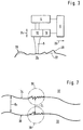
- FIG. 3 shows a schematic illustration of that in FIG. 1 shown device with the laser beam generating device 4, the control device 6 and the imaging optics 12 from which the laser beam 5 emerges and on the surface of the workpiece 14 to be machined occurs, which is shown as contour line 20 (actual shape).
- the contour measuring device 18 is here in the imaging optics 12 integrated and the working beam 5 is simultaneously as Measuring beam used for the contour measuring device 18.
- the control device 6 can not be closer by means Actuators shown the distance between Imaging optics 12 and the workpiece surface 20 vary, which is indicated by a double arrow 24.
- Actuators are also the feed with respect to the workpiece 14 causes and controls. This is by an arrow 26 shown.
- the No transition from the current form 20 to the target form 22 necessarily with a single sweep of the Laser beam 5 reached. In the one already painted Area 28 is still a discrepancy between TARGET and Can be seen.
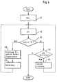
- Fig. 4 shows a flow chart for explaining essential Sub-steps of the inventive method with which Surface of a workpiece 14 from the actual shape in the SHOULD form is transferred.
- a step S1 is first the desired TARGET shape in a reference coordinate system fixed.
- the TARGET shape can be, for example, in the form of CNC or CAD data are available.
- a step S2 then the actual form of the still unprocessed or pre-machined workpiece 14 determined and in coordinates of the reference coordinate system.
- Step S3 is queried whether the actual value at the machining partial surface of the workpiece 14 already with the SHOULD value match or not. If it does asked in a step S4 whether all partial areas already exist edited or not. If so, it is Processing finished. Are not all partial areas processed, the transition to next partial area and the processing starts again at Step S2.
- Step S6 branches in which, based on the comparison of TARGET and ACTUAL data, based on external entries about the machining material, etc. the machining parameters for the Laser 2 and the strategy of machining is determined.
- step S7 the laser processing of the respective partial area corresponding to that in step S6 determined parameters executed. Then it will go back branches to step S2.
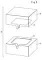
- Fig. 5 shows schematically a molding tool 30, which consists of two complementary parts 32 and 33.
- the two parts 32 and 33 can be put together and then by them enclosed cavity is then complemented by two Partial sealing surfaces 34 and 36 sealed.
- the Partial sealing surfaces 34 and 36 can have almost any shape be.
- Fig. 6 shows a flow chart for explaining the manufacture the sealing surfaces 34 and 36 with the method according to of the present invention.
- a step S1 first the target shape of only one of the two partial sealing surfaces, for example the partial sealing surface 34, fixed. Then the processing takes place according to the Steps S2 to S7 according to Fig. 4. Is the first partial sealing surface 34 completely processed, so in one Step S8 is the current form of processing after processing first partial sealing surface 34 as a target shape for the second Partial sealing surface 36 fixed. Processing the second Partial sealing surface 36 is then again analogous to that Steps S2 to S7 according to FIG. 4.
- FIG. 7 schematically shows a section through a part of the parts 32 and 33 of the molding tool 30 or a section through a part of the part sealing surfaces 34 and 36, areas 38 and 39 being shown enlarged.
- the two parts 32 and 33 more precisely their partial sealing surfaces 34 and 36, are arranged at a distance D from one another. Due to the roughness of the pre-machined partial sealing surfaces 34 and 36, the actual distance D i (actual distance) varies between opposing surface elements of the partial sealing surfaces 34 and 36.
- the two mold parts 32 and 33 are spatially fixed at a fixed distance from one another and the actual distance D i between opposing surface elements of the partial sealing surfaces 34 and 36 is measured.
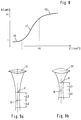
- FIG. 8 shows the material removal A caused by the laser beam 5 in ⁇ m as a function of the laser fluence (power density times irradiation time) in J / cm 2 .
- the result is a curve in the form of an elongated S with a flat curve in the area of low laser fluence, reference numeral 40, and in the area of high laser fluence, reference numeral 42, and a steep curve in the area of medium laser fluence, reference numeral 41.
- Those indicated in FIG. 8 Values apply to a copper vapor laser system as is known from DE-OS 44 12 443 and to which reference is made in full here.
- the region 40 or region 41 ends at approximately 1 J / cm 2 and the end of region 41 or the beginning of region 42 is approximately 250 J / cm 2 .
- the aluminum removal is in the range of 1 ⁇ m, region 40, and in region 42 with a laser fluence above 250 J / cm 2 , the aluminum removal is approximately 80 ⁇ m.
- the laser 2 is, according to the invention, in the areas 40 and 42 operated with a flat curve, since there is little Fluence fluctuations, such as those caused by variations the distance between the laser head 3 and to be machined Area due to vibration occur, hardly affect the size of the material removal. Hence is controlled and precise shaping easier. Of the Area 40 with low laser intensity is special advantageous when laser polishing, because a laser polishing large material removal is not desired.
- a focusing device or a Imaging optics 12 used which have a large Rayleigh length, preferably have SSge $$ 300 ⁇ m. It is known that real optical systems the focus B is not an ideal one mathematical point, but a spatial area.
- the Rayleigh length is a measure of the variation of the Cross section of the beam in the area of the geometric Focus. The smaller the Rayleigh length, the more the real beam matches the geometric one Beam path.
- 9a shows an optic 12 with a large Rayleigh length and 9b an optics 12 'with a small Rayleigh length. Varies in both cases the distance between imaging optics 12, 12 'and the area to be machined around the focal point B by ⁇ D, so fluctuates with a small Rayleigh length - Fig. 9b - Cross-sectional area F of the beam in the area between + ⁇ D and - ⁇ D and thus the laser intensity considerably more than with a large Rayleigh length - Fig. 9a.
- a Laser device 2 with an imaging optics 12 with a large Rayleigh length is therefore less sensitive to Vibration fluctuations.
Landscapes
- Engineering & Computer Science (AREA)
- Physics & Mathematics (AREA)
- Optics & Photonics (AREA)
- Mechanical Engineering (AREA)
- Plasma & Fusion (AREA)
- General Physics & Mathematics (AREA)
- Automation & Control Theory (AREA)
- Manufacturing & Machinery (AREA)
- Human Computer Interaction (AREA)
- Laser Beam Processing (AREA)
- Length Measuring Devices By Optical Means (AREA)
- Grinding And Polishing Of Tertiary Curved Surfaces And Surfaces With Complex Shapes (AREA)
- Length Measuring Devices With Unspecified Measuring Means (AREA)
- Encapsulation Of And Coatings For Semiconductor Or Solid State Devices (AREA)
- Moulds For Moulding Plastics Or The Like (AREA)
- Manufacturing Of Printed Circuit Boards (AREA)
Abstract
Description
- Fig. 1
- eine schematische Darstellung einer beispielhaften Vorrichtung zur Ausführung des erfindungsgemäßen Verfahrens,
- Fig. 2
- ein Detail der Vorrichtung nach Fig. 1,
- Fig. 3
- eine schematische Darstellung zur Erläuterung der Arbeitsweise der Vorrichtung nach Fig. 1 und 2,
- Fig. 4
- ein Flußdiagramm zur Veranschaulichung wesentlicher Teilschritte des erfinderischen Verfahrens,
- Fig. 5
- eine schematische Darstellung eines Formwerkzeuges mit zwei komplementären Teilen,
- Fig. 6
- ein Flußdiagramm zur Erläuterung einer ersten Ausführungsform des Verfahrens zur Herstellung von Dichtflächen gemäß der vorliegenden Erfindung,
- Fig. 7
- eine schematische Darstellung zur Erläuterung einer zweiten Ausführungsform des Verfahrens zur Herstellung von Dichtflächen,
- Fig. 8
- eine qualitative Darstellung des Materialabtrags als Funktion der Laserfluenz, und
- Fig. 9a und 9b
- Abbildungsoptiken mit großer und kleiner Rayleighlänge.
Claims (11)
- Verfahren zur Herstellung von Dichtflächen an komplementären Formwerkzeugen mit wenigstens zwei komplementären Teildichtflächen, mit folgenden Verfahrensschritten:a) Festlegen der dreidimensionalen Koordinaten einer der komplementären Teildichtflächen (Soll-Daten);b) Abtasten wenigstens der einen komplementären Teildichtfläche mittels einer 3D-Konturmeßeinrichtung zum Bestimmen der genauen, tatsächlichen Oberflächenform dieser Teildichtflächen in einem Referenzkoordinatensystem (IST-Daten);c) Errechnen von Bearbeitungsparamentern für eine Strahlbearbeitungseinrichtung zum Abtragen von Materialschichten aufgrund der ermittelten SOLL-Daten und aufgrund der durch die 3D-Konturmeßeinrichtung ermittelten IST-Daten;d) Bearbeiten der einen komplementären Teildichtfläche mit der Strahlbearbeitungseinrichtung auf der Basis der in Schritt c) ermittelten Bearbeitungsparameter;e) erneutes Abtasten der in Schritt d) bearbeiteten Teildichtfläche mittels der 3D-Konturmeßeinrichtung zum Bestimmen der nunmehr nach der Bearbeitung vorliegenden Oberflächenform der Teildichtflächen (aktualisierte IST-Daten);f) gegebenenfalls Wiederholung der Schritte b) bis e) bis die Abweichung der SOLL-Daten von den IST-Daten innerhalb eines bestimmten Toleranzbereiches liegt; undg) Festlegen der zuletzt in Schritt e) ermittelten Oberflächenform der einen bereits bearbeiteten komplementären Teildichtfläche als SOLL-Form für die andere komplementäre Teildichtfläche; undh) Bearbeiten der anderen komplementären Teildichtfläche gemäß den Schritten c) bis f).
- Verfahren zur Herstellung von Dichtflächen an komplementären Formwerkzeugen mit wenigstens zwei komplementären Teildichtflächen, mit folgenden Verfahrensschritten:a) Anordnen der komplementären Formwerkzeuge derart, daß der Abstand einander entsprechender Flächenabschnitte der Teildichtflächen innerhalb eines ersten Toleranzbereichs liegt;b) Bestimmen des genauen Abstands einander entsprechender Flächenabschnitte der Teildichtflächen mittels einer 3D-Konturmeßeinrichtung (IST-Daten);c) Festlegen eines SOLL-Abstandes (SOLL-Daten), der mindestens so groß wie der größte IST-Abstand ist;d) Errechnen von Bearbeitungsparamentern für eine Strahlbearbeitungseinrichtung zum Abtragen von Materialschichten aufgrund der ermittelten SOLL-Daten und aufgrund der durch die 3D-Konturmeßeinrichtung ermittelten IST-Daten;e) Bearbeiten wenigstens einer der komplementären Teildichtflächen mit der Strahlbearbeitungseinrichtung auf der Basis der in Schritt d) ermittelten Bearbeitungsparameter;f) erneutes Bestimmen des genauen Abstandes einander entsprechender Flächenabschnitte der Teildichtflächen mittels der 3D-Konturmeßeinrichtung (aktualisierte IST-Daten);g) gegebenenfalls Wiederholung der Schritte d) bis f) bis die Abweichung der SOLL-Daten von den IST-Daten innerhalb eines zweiten Toleranzbereiches liegt, der kleiner als der erste Toleranzbereich ist.
- Verfahren nach wenigstens einem der vorhergehenden Ansprüche 1 oder 2, dadurch gekennzeichnet, daß die Querschnittsfläche des auf der zu bearbeitenden Teildichtfläche auftreffenden Arbeitsstrahls die Teildichtfläche in ihrer gesamten Breite überdeckt.
- Verfahren nach einem der vorhergehenden Ansprüche, dadurch gekennzeichnet, daß die Festlegung der SOLL-Daten und die erstmalige Ermittlung der IST-Daten vertauscht sind.
- Verfahren nach wenigstens einem der vorhergehenden Ansprüche, dadurch gekennzeichnet, daß die Strahlbearbeitungseinrichtung in einem Bereich betrieben wird, in dem die Änderungen des Materialabtrags aufgrund von Schwankungen der Strahlintensität möglichst gering sind.
- Verfahren nach Anspruch 5, dadurch gekennzeichnet, daß die Strahlbearbeitungseinrichtung beim Laserpolieren in einem Bereich mit geringer Laserintensität betrieben wird.
- Verfahren nach wenigstens einem der vorhergehenden Ansprüche, dadurch gekennzeichnet, daß die 3D-Konturmeßeinrichtung mit Triangulation arbeitet.
- Verfahren nach wenigstens einem der vorhergehenden Ansprüche, dadurch gekennzeichnet, daß die Strahlbearbeitungseinrichtung einen Laserstrahl als Arbeitsstrahl erzeugt.
- Verfahren nach Anspruch 8, dadurch gekennzeichnet, daß die Strahlbearbeitungseinrichtung einen gepulsten Laserstrahl erzeugt.
- Verfahren nach Anspruch 8 oder 9, dadurch gekennzeichnet, daß der Arbeitsstrahl der Strahlbearbeitungseinrichtung als Meßstrahl der 3D-Konturmeßeinrichtung verwendet wird.
- Verfahren nach wenigstens einem der vorhergehenden Ansprüche, dadurch gekennzeichnet, daß Arbeitsstrahl senkrecht zu der zu bearbeitenden Oberfläche ausgerichtet wird.
Applications Claiming Priority (3)
| Application Number | Priority Date | Filing Date | Title |
|---|---|---|---|
| DE29505985U DE29505985U1 (de) | 1995-04-06 | 1995-04-06 | Vorrichtung zum Bearbeiten, insbesondere zum Polieren und Strukturieren von beliebigen 3D-Formflächen mittels eines Laserstrahls |
| DE29505985U | 1995-04-06 | ||
| EP96909025A EP0819036B1 (de) | 1995-04-06 | 1996-04-09 | Verfahren und vorrichtung zum bearbeiten von beliebigen 3d-formflächen mittels laser |
Related Parent Applications (2)
| Application Number | Title | Priority Date | Filing Date |
|---|---|---|---|
| EP96909025A Division EP0819036B1 (de) | 1995-04-06 | 1996-04-09 | Verfahren und vorrichtung zum bearbeiten von beliebigen 3d-formflächen mittels laser |
| EP96909025.7 Division | 1996-10-10 |
Publications (2)
| Publication Number | Publication Date |
|---|---|
| EP0854004A1 true EP0854004A1 (de) | 1998-07-22 |
| EP0854004B1 EP0854004B1 (de) | 2001-10-04 |
Family
ID=8006554
Family Applications (2)
| Application Number | Title | Priority Date | Filing Date |
|---|---|---|---|
| EP96909025A Expired - Lifetime EP0819036B1 (de) | 1995-04-06 | 1996-04-09 | Verfahren und vorrichtung zum bearbeiten von beliebigen 3d-formflächen mittels laser |
| EP98103286A Expired - Lifetime EP0854004B1 (de) | 1995-04-06 | 1996-04-09 | Verfahren zum Herstellen von Dichtflächen an komplementären Formwerkzeugen |
Family Applications Before (1)
| Application Number | Title | Priority Date | Filing Date |
|---|---|---|---|
| EP96909025A Expired - Lifetime EP0819036B1 (de) | 1995-04-06 | 1996-04-09 | Verfahren und vorrichtung zum bearbeiten von beliebigen 3d-formflächen mittels laser |
Country Status (13)
| Country | Link |
|---|---|
| US (1) | US6043452A (de) |
| EP (2) | EP0819036B1 (de) |
| JP (1) | JP3258331B2 (de) |
| KR (1) | KR100311839B1 (de) |
| AT (2) | ATE206340T1 (de) |
| AU (1) | AU5269496A (de) |
| BR (1) | BR9604851A (de) |
| CA (1) | CA2217372C (de) |
| DE (3) | DE29505985U1 (de) |
| DK (2) | DK0854004T3 (de) |
| ES (2) | ES2162356T3 (de) |
| PT (1) | PT854004E (de) |
| WO (1) | WO1996031315A1 (de) |
Cited By (3)
| Publication number | Priority date | Publication date | Assignee | Title |
|---|---|---|---|---|
| DE102012111796A1 (de) * | 2012-12-05 | 2014-06-18 | Reinhard Caliebe | Bearbeitungseinrichtung für ein Werkstück |
| DE102012111797A1 (de) * | 2012-12-05 | 2014-06-18 | Reinhard Caliebe | Bearbeitungseinrichtung für ein Werkstück |
| DE102018209929A1 (de) * | 2018-06-20 | 2019-12-24 | Bayerische Motoren Werke Aktiengesellschaft | Verfahren zum Bearbeiten eines Bauteils eines Kraftfahrzeugs |
Families Citing this family (79)
| Publication number | Priority date | Publication date | Assignee | Title |
|---|---|---|---|---|
| GB2328636A (en) * | 1997-08-29 | 1999-03-03 | Rye Machinery Ltd | A support for a laser tool |
| ES2200524T3 (es) * | 1998-10-05 | 2004-03-01 | Mystix Limited | Articulo de plastico y procedimiento de fabricacion de dicho articulo. |
| KR100628438B1 (ko) * | 1998-12-04 | 2006-12-05 | 삼성전자주식회사 | 액정표시기 패널의 제조방법 |
| DE29904489U1 (de) * | 1999-03-11 | 1999-05-27 | Precitec GmbH, 76571 Gaggenau | Arbeitskopf zur Bearbeitung eines Werkstücks mittels eines Laserstrahls |
| US6300595B1 (en) * | 1999-06-03 | 2001-10-09 | High Tech Polishing, Inc. | Method of three dimensional laser engraving |
| USD437332S1 (en) | 1999-07-23 | 2001-02-06 | Lillbacka Jetair Oy | Cutting head support frame |
| US6552301B2 (en) | 2000-01-25 | 2003-04-22 | Peter R. Herman | Burst-ultrafast laser machining method |
| KR100364195B1 (ko) * | 2000-06-12 | 2002-12-11 | 한국기계연구원 | 엑사이머 레이저빔을 이용한 3차원 형상을 갖는 물품의 제조방법 및 제조장치 |
| US6492615B1 (en) * | 2000-10-12 | 2002-12-10 | Scimed Life Systems, Inc. | Laser polishing of medical devices |
| US7767928B2 (en) | 2001-09-05 | 2010-08-03 | Lasertec Gmbh | Depth measurement and depth control or automatic depth control for a hollow to be produced by a laser processing device |
| DE10228743B4 (de) | 2002-06-27 | 2005-05-04 | Fraunhofer-Gesellschaft zur Förderung der angewandten Forschung e.V. | Verfahren zum Glätten und Polieren von Oberflächen durch Bearbeitung mit Laserstrahlung |
| DE10317579B4 (de) * | 2003-04-16 | 2016-04-14 | Lasertec Gmbh | Verfahren und Vorrichtung zur Herstellung eines Gesenks in einem Werkstück |
| DE10324439B4 (de) * | 2003-05-28 | 2008-01-31 | Lasertec Gmbh | Verfahren und Vorrichtung zur Herstellung eines Gesenks |
| DE10342750B4 (de) * | 2003-09-16 | 2008-06-19 | Fraunhofer-Gesellschaft zur Förderung der angewandten Forschung e.V. | Verfahren zum Glätten und Polieren oder zum Strukturieren von Oberflächen mit Laserstrahlung |
| DE10345081A1 (de) * | 2003-09-26 | 2005-05-19 | Peguform Gmbh & Co. Kg | Verfahren zur Bearbeitung einer dreidimensionalen Oberfläche |
| JP5013699B2 (ja) * | 2005-10-21 | 2012-08-29 | 株式会社キーエンス | 3次元加工データ設定装置、3次元加工データ設定方法、3次元加工データ設定プログラム、コンピュータで読み取り可能な記録媒体及び記録した機器並びにレーザ加工装置 |
| US7449699B1 (en) | 2006-04-20 | 2008-11-11 | Sandia Corporation | Method and apparatus for creating a topography at a surface |
| US20070279969A1 (en) * | 2006-06-02 | 2007-12-06 | Raytheon Company | Intrusion detection apparatus and method |
| JP5132900B2 (ja) * | 2006-06-28 | 2013-01-30 | 株式会社キーエンス | レーザ加工条件設定装置、レーザ加工装置、レーザ加工条件設定方法、レーザ加工条件設定プログラム |
| JP4958489B2 (ja) * | 2006-06-30 | 2012-06-20 | 株式会社キーエンス | レーザ加工装置、レーザ加工条件設定装置、レーザ加工条件設定方法、レーザ加工条件設定プログラム |
| JP4795886B2 (ja) * | 2006-07-27 | 2011-10-19 | 株式会社キーエンス | レーザ加工装置、レーザ加工条件設定装置、レーザ加工条件設定方法、レーザ加工条件設定プログラム |
| JP4956107B2 (ja) * | 2006-09-15 | 2012-06-20 | 株式会社キーエンス | レーザ加工データ生成装置、レーザ加工データ生成方法、コンピュータプログラム及びレーザマーキングシステム |
| KR100784939B1 (ko) | 2006-12-22 | 2007-12-13 | 주식회사 아스트 | 3차원 형상 정보를 활용한 항공기 동체 제작 장비의 다축동시 제어방법 |
| US8674259B2 (en) * | 2008-05-28 | 2014-03-18 | Caterpillar Inc. | Manufacturing system for producing reverse-tapered orifice |
| US20110087457A1 (en) * | 2009-10-09 | 2011-04-14 | Furmanite Worldwide, Inc. | Surface measurement, selection, and machining |
| US20110087363A1 (en) * | 2009-10-09 | 2011-04-14 | Furmanite Worldwide, Inc. | Surface measurement, selection, and machining |
| US20110085175A1 (en) * | 2009-10-09 | 2011-04-14 | Furmanite Worldwide, Inc. | Surface measurement, selection, and machining |
| US9056584B2 (en) | 2010-07-08 | 2015-06-16 | Gentex Corporation | Rearview assembly for a vehicle |
| DE102010033053B4 (de) * | 2010-08-02 | 2013-03-07 | Fraunhofer-Gesellschaft zur Förderung der angewandten Forschung e.V. | Verfahren zum formgebenden Umschmelzen von Werkstücken |
| DE102011103793A1 (de) * | 2011-03-10 | 2012-09-27 | Fraunhofer-Gesellschaft zur Förderung der angewandten Forschung e.V. | Verfahren zur Fertigung optischer Elemente durch Bearbeitung mit energetischer Strahlung |
| JP5459255B2 (ja) * | 2011-04-08 | 2014-04-02 | 株式会社安川電機 | ロボットシステム |
| EP2511656A1 (de) * | 2011-04-14 | 2012-10-17 | Hexagon Technology Center GmbH | Vermessungssystem zur Bestimmung von 3D-Koordinaten einer Objektoberfläche |
| FR2974746B1 (fr) * | 2011-05-02 | 2014-07-18 | Snecma | Procede de nettoyage et de decapage d'une aube de turbomoteur au moyen d'un laser impulsionnel |
| DE102011078825B4 (de) * | 2011-07-07 | 2018-07-19 | Sauer Gmbh Lasertec | Verfahren und Laserbearbeitungsmaschine zur Bearbeitung eines Werkstücks |
| US10052726B2 (en) | 2011-12-14 | 2018-08-21 | Panasonic Intellectual Property Management Co., Ltd. | Method for creating machining data for use in hybrid ultraprecision machining device, and hybrid ultraprecision machining device |
| WO2013089282A1 (ja) | 2011-12-14 | 2013-06-20 | パナソニック株式会社 | 超精密複合加工装置における加工手段の判断方法および超精密複合加工装置 |
| WO2013098567A1 (en) * | 2011-12-28 | 2013-07-04 | Femtonics Kft. | Method for the 3-dimensional measurement of a sample with a measuring system comprising a laser scanning microscope and such measuring system |
| US9316347B2 (en) | 2012-01-24 | 2016-04-19 | Gentex Corporation | Rearview assembly with interchangeable rearward viewing device |
| US8879139B2 (en) | 2012-04-24 | 2014-11-04 | Gentex Corporation | Display mirror assembly |
| US8864322B2 (en) | 2012-08-24 | 2014-10-21 | Gentex Corporation | Shaped rearview mirror assembly |
| DE102012107827A1 (de) * | 2012-08-24 | 2014-02-27 | Sandvik Surface Solutions Division Of Sandvik Materials Technology Deutschland Gmbh | Verfahren zur Erzeugung von Glanzeffekten auf Presswerkzeugen |
| US9327648B2 (en) | 2013-01-04 | 2016-05-03 | Gentex Corporation | Rearview assembly with exposed carrier plate |
| US9488892B2 (en) | 2013-01-09 | 2016-11-08 | Gentex Corporation | Printed appliqué and method thereof |
| FI20135385L (fi) * | 2013-04-18 | 2014-10-19 | Cajo Tech Oy | Metallipintojen värimerkintä |
| KR101470175B1 (ko) * | 2013-06-26 | 2014-12-08 | 현대자동차주식회사 | 금형의 외관 레이저가공 방법 |
| AU2014326772B2 (en) | 2013-09-24 | 2017-07-20 | Gentex Corporation | Display mirror assembly |
| US9694751B2 (en) | 2014-09-19 | 2017-07-04 | Gentex Corporation | Rearview assembly |
| WO2016073848A1 (en) | 2014-11-07 | 2016-05-12 | Gentex Corporation | Full display mirror actuator |
| KR101977685B1 (ko) | 2014-11-13 | 2019-05-13 | 젠텍스 코포레이션 | 디스플레이를 갖춘 후방 미러 시스템 |
| KR101997815B1 (ko) | 2014-12-03 | 2019-07-08 | 젠텍스 코포레이션 | 디스플레이 미러 어셈블리 |
| USD746744S1 (en) | 2014-12-05 | 2016-01-05 | Gentex Corporation | Rearview device |
| CN104759753B (zh) * | 2015-03-30 | 2016-08-31 | 江苏大学 | 多系统自动化协调工作提高激光诱导空化强化的方法 |
| JP2018513810A (ja) | 2015-04-20 | 2018-05-31 | ジェンテックス コーポレイション | 装飾を備えた後方視認アセンブリ |
| WO2016187215A1 (en) | 2015-05-18 | 2016-11-24 | Gentex Corporation | Full display rearview device |
| US10029330B2 (en) * | 2015-06-17 | 2018-07-24 | The Boeing Company | Hybrid laser machining of multi-material stack-ups |
| US9994156B2 (en) | 2015-10-30 | 2018-06-12 | Gentex Corporation | Rearview device |
| WO2017075420A1 (en) | 2015-10-30 | 2017-05-04 | Gentex Corporation | Toggle paddle |
| USD845851S1 (en) | 2016-03-31 | 2019-04-16 | Gentex Corporation | Rearview device |
| USD817238S1 (en) | 2016-04-29 | 2018-05-08 | Gentex Corporation | Rearview device |
| US10025138B2 (en) | 2016-06-06 | 2018-07-17 | Gentex Corporation | Illuminating display with light gathering structure |
| JP6348149B2 (ja) * | 2016-07-08 | 2018-06-27 | ファナック株式会社 | ロボットを用いてレーザ加工を行うレーザ加工ロボットシステム |
| USD809984S1 (en) | 2016-12-07 | 2018-02-13 | Gentex Corporation | Rearview assembly |
| DE102017002986B4 (de) | 2016-12-13 | 2019-08-29 | AIXLens GmbH | Verfahren zur Herstellung einer transmitiven Optik und Intraokularlinse |
| DE102017007219A1 (de) | 2016-12-13 | 2018-06-14 | Fraunhofer-Gesellschaft zur Förderung der angewandten Forschung e.V. | Verfahren zur Herstellung einer transmitiven oder reflektiven Optik und Linse |
| USD854473S1 (en) | 2016-12-16 | 2019-07-23 | Gentex Corporation | Rearview assembly |
| CN108393579A (zh) * | 2017-02-07 | 2018-08-14 | 京东方科技集团股份有限公司 | 激光加工装置及激光加工方法 |
| JP6464213B2 (ja) * | 2017-02-09 | 2019-02-06 | ファナック株式会社 | レーザ加工ヘッドおよび撮影装置を備えるレーザ加工システム |
| EP3406389A1 (de) * | 2017-05-23 | 2018-11-28 | Siemens Aktiengesellschaft | Verfahren zur erkennung und bearbeitung von definierten konturen bei der durchtrennung eines festkörpers mittels eines hochenergiestrahls |
| DE102017113804B4 (de) * | 2017-06-22 | 2020-08-06 | Rolf Rascher | Verfahren sowie Vorrichtung zur Überwachung eines Laserpolierprozesses |
| US10744539B2 (en) * | 2017-10-27 | 2020-08-18 | The Boeing Company | Optimized-coverage selective laser ablation systems and methods |
| WO2019116452A1 (ja) * | 2017-12-12 | 2019-06-20 | 株式会社ニコン | 処理装置及び処理方法、加工方法、並びに、造形装置及び造形方法 |
| DE102018102108B4 (de) * | 2018-01-31 | 2019-10-10 | Acsys Lasertechnik Gmbh | Verfahren zum laserbasierten Erzeugen einer Struktur an einer Spanfläche eines spanenden Werkzeugs |
| DE102018106362A1 (de) * | 2018-03-19 | 2019-09-19 | Technische Universität Hamburg | Vorrichtungen und verfahren zum bearbeiten metallischer objekte |
| DE102018108145A1 (de) * | 2018-04-06 | 2019-10-10 | Volkswagen Ag | Verfahren zur Bearbeitung von Oberflächen von mittels 3D-Druck gefertigten Bauteilen sowie ein solches bearbeitetes Bauteil |
| DE102018122605A1 (de) | 2018-09-14 | 2020-03-19 | Fraunhofer-Gesellschaft zur Förderung der angewandten Forschung e.V. | Verfahren zum Glätten eines Bauteiloberflächenbereichs |
| TWI861185B (zh) * | 2019-08-23 | 2024-11-11 | 日商Tocalo股份有限公司 | 表面處理方法 |
| CN112756777B (zh) * | 2020-12-29 | 2022-12-02 | 华中科技大学 | 一种金属表面的激光发黑处理方法 |
| CN114959691A (zh) * | 2022-06-10 | 2022-08-30 | 北京工商大学 | 一种3d打印钛合金的表面改性设备及其表面改性方法 |
| CN120306820B (zh) * | 2025-06-17 | 2025-08-08 | 天津远东恒嘉新材料有限公司 | 用于金刚石复合片的激光研磨控制系统 |
Citations (1)
| Publication number | Priority date | Publication date | Assignee | Title |
|---|---|---|---|---|
| US4986664A (en) * | 1984-02-07 | 1991-01-22 | International Technical Associates | System and process for controlled removal of material to produce a desired surface contour |
Family Cites Families (14)
| Publication number | Priority date | Publication date | Assignee | Title |
|---|---|---|---|---|
| DE2624121A1 (de) * | 1976-05-28 | 1977-12-15 | Siemens Ag | Verfahren zum genauen bearbeiten eines im arbeitsfeld eines bearbeitungslasers angeordneten werkstueckes sowie vorrichtung zur ausuebung des verfahrens |
| US4469930A (en) * | 1981-07-17 | 1984-09-04 | Fuji Tool & Die Co., Ltd. | Three-dimensional laser cutting system by a playback method |
| US4752668A (en) * | 1986-04-28 | 1988-06-21 | Rosenfield Michael G | System for laser removal of excess material from a semiconductor wafer |
| US4825035A (en) * | 1986-09-20 | 1989-04-25 | Mitsubishi Denki Kabushiki Kaisha | Control apparatus for energy beam hardening |
| JPS63101092A (ja) * | 1986-10-18 | 1988-05-06 | Toshiba Corp | レ−ザ加工装置 |
| US4977512A (en) | 1987-02-05 | 1990-12-11 | Shibuya Kogyo Co., Ltd. | Three dimensional simultaneous machining and measuring system |
| DE3711470A1 (de) * | 1987-04-04 | 1988-10-27 | Fraunhofer Ges Forschung | Verfahren zum herstellen eines dreidimensionalen modells |
| DD263447A1 (de) * | 1987-09-02 | 1989-01-04 | Zeiss Jena Veb Carl | Anordnung zur operativen behandlung der augenhornhaut |
| US4915757A (en) * | 1988-05-05 | 1990-04-10 | Spectra-Physics, Inc. | Creation of three dimensional objects |
| US4914270A (en) * | 1988-11-08 | 1990-04-03 | University Of Southern California | Method and apparatus for shaping articles using a laser beam |
| US5057184A (en) * | 1990-04-06 | 1991-10-15 | International Business Machines Corporation | Laser etching of materials in liquids |
| US5475197A (en) * | 1992-06-17 | 1995-12-12 | Carl-Zeiss-Stiftung | Process and apparatus for the ablation of a surface |
| DE4333501C2 (de) * | 1993-10-01 | 1998-04-09 | Univ Stuttgart Strahlwerkzeuge | Verfahren zur Bestimmung der momentanen und Herbeiführung einer gewünschten Eindringtiefe eines Bearbeitungslaserstrahles in ein Werkstück sowie Vorrichtung zur Durchführung dieses Verfahrens |
| US5656186A (en) * | 1994-04-08 | 1997-08-12 | The Regents Of The University Of Michigan | Method for controlling configuration of laser induced breakdown and ablation |
-
1995
- 1995-04-06 DE DE29505985U patent/DE29505985U1/de not_active Expired - Lifetime
-
1996
- 1996-04-09 ES ES98103286T patent/ES2162356T3/es not_active Expired - Lifetime
- 1996-04-09 CA CA002217372A patent/CA2217372C/en not_active Expired - Fee Related
- 1996-04-09 AU AU52694/96A patent/AU5269496A/en not_active Abandoned
- 1996-04-09 WO PCT/DE1996/000621 patent/WO1996031315A1/de not_active Ceased
- 1996-04-09 DE DE59601716T patent/DE59601716D1/de not_active Expired - Lifetime
- 1996-04-09 EP EP96909025A patent/EP0819036B1/de not_active Expired - Lifetime
- 1996-04-09 AT AT98103286T patent/ATE206340T1/de not_active IP Right Cessation
- 1996-04-09 BR BR9604851-4A patent/BR9604851A/pt not_active Application Discontinuation
- 1996-04-09 DK DK98103286T patent/DK0854004T3/da active
- 1996-04-09 ES ES96909025T patent/ES2130808T3/es not_active Expired - Lifetime
- 1996-04-09 AT AT96909025T patent/ATE179107T1/de not_active IP Right Cessation
- 1996-04-09 JP JP52986296A patent/JP3258331B2/ja not_active Expired - Fee Related
- 1996-04-09 EP EP98103286A patent/EP0854004B1/de not_active Expired - Lifetime
- 1996-04-09 US US08/930,429 patent/US6043452A/en not_active Expired - Fee Related
- 1996-04-09 DK DK96909025T patent/DK0819036T3/da active
- 1996-04-09 KR KR1019970707004A patent/KR100311839B1/ko not_active Expired - Fee Related
- 1996-04-09 DE DE59607842T patent/DE59607842D1/de not_active Expired - Lifetime
- 1996-04-09 PT PT98103286T patent/PT854004E/pt unknown
Patent Citations (1)
| Publication number | Priority date | Publication date | Assignee | Title |
|---|---|---|---|---|
| US4986664A (en) * | 1984-02-07 | 1991-01-22 | International Technical Associates | System and process for controlled removal of material to produce a desired surface contour |
Cited By (5)
| Publication number | Priority date | Publication date | Assignee | Title |
|---|---|---|---|---|
| DE102012111796A1 (de) * | 2012-12-05 | 2014-06-18 | Reinhard Caliebe | Bearbeitungseinrichtung für ein Werkstück |
| DE102012111797A1 (de) * | 2012-12-05 | 2014-06-18 | Reinhard Caliebe | Bearbeitungseinrichtung für ein Werkstück |
| DE102012111796B4 (de) * | 2012-12-05 | 2017-04-20 | Reinhard Caliebe | Bearbeitungseinrichtung für ein Werkstück |
| DE102012111797B4 (de) * | 2012-12-05 | 2017-04-20 | Reinhard Caliebe | Bearbeitungseinrichtung für ein Werkstück |
| DE102018209929A1 (de) * | 2018-06-20 | 2019-12-24 | Bayerische Motoren Werke Aktiengesellschaft | Verfahren zum Bearbeiten eines Bauteils eines Kraftfahrzeugs |
Also Published As
| Publication number | Publication date |
|---|---|
| ATE179107T1 (de) | 1999-05-15 |
| BR9604851A (pt) | 1999-11-30 |
| DE59607842D1 (de) | 2001-11-08 |
| JPH10508256A (ja) | 1998-08-18 |
| DE59601716D1 (de) | 1999-05-27 |
| ES2162356T3 (es) | 2001-12-16 |
| EP0854004B1 (de) | 2001-10-04 |
| CA2217372C (en) | 2001-10-02 |
| WO1996031315A1 (de) | 1996-10-10 |
| ES2130808T3 (es) | 1999-07-01 |
| CA2217372A1 (en) | 1996-10-10 |
| DE29505985U1 (de) | 1995-07-20 |
| AU5269496A (en) | 1996-10-23 |
| DK0854004T3 (da) | 2002-01-07 |
| KR19980703605A (ko) | 1998-12-05 |
| JP3258331B2 (ja) | 2002-02-18 |
| EP0819036A1 (de) | 1998-01-21 |
| DK0819036T3 (da) | 1999-10-25 |
| EP0819036B1 (de) | 1999-04-21 |
| US6043452A (en) | 2000-03-28 |
| PT854004E (pt) | 2002-02-28 |
| ATE206340T1 (de) | 2001-10-15 |
| KR100311839B1 (ko) | 2002-11-18 |
Similar Documents
| Publication | Publication Date | Title |
|---|---|---|
| EP0854004B1 (de) | Verfahren zum Herstellen von Dichtflächen an komplementären Formwerkzeugen | |
| EP0790875B1 (de) | Verfahren und vorrichtung zur herstellung von metallischen werkstücken | |
| DE69116219T2 (de) | Zielbereichprofilierung von optischen Oberflächen durch Ecimer Laser Lichtabschmelzung | |
| DE3934587C2 (de) | Verfahren zum Herstellen von mittels Laserstrahlung erzeugter, hochpräziser Durchgangsbohrungen in Werkstücken | |
| DE19935274C1 (de) | Vorrichtung und Verfahren zur Herstellung von Bauteilen aus einer Werkstoffkombination | |
| DE102017202725B3 (de) | Vorrichtung und Verfahren zum Kalibrieren eines Bestrahlungssystems, das zum Herstellen eines dreidimensionalen Werkstücks verwendet wird | |
| DE3711470C2 (de) | ||
| DE102016111455B4 (de) | Verfahren zur Bestimmung einer Referenz-Fokuslage sowie Werkzeugmaschine | |
| EP3771551A1 (de) | Verfahren zum kalibrieren einer vorrichtung zum herstellen eines dreidimensionalen objekts | |
| DE69215851T2 (de) | Verfahren und vorrichtung zum laserbearbeiten | |
| DE102021103206A1 (de) | Verfahren zum Optimieren einer Bearbeitungszeit eines Laserbearbeitungsprozesses, Verfahren zum Durchführen eines Laserbearbeitungsprozesses an einem Werkstück und Laserbearbeitungssystem, welches eingerichtet ist, um diese durchzuführen | |
| CH656568A5 (de) | Verfahren und vorrichtung zur detektion des brennpunktes eines laserstrahles in einer laserwerkzeugmaschine. | |
| DE102018124208A1 (de) | Verfahren und Vorrichtung zur Überwachung eines Bearbeitungsprozesses eines Werkstücks mittels eines Laserstrahls | |
| DE102018125436A1 (de) | Verfahren zur materialabtragenden Laserbearbeitung eines Werkstücks | |
| DE69215855T2 (de) | Verfahren zum laserdurchbohren | |
| DE19804577C2 (de) | Verfahren und Vorrichtung zur Beseitigung von Formabweichungen an metallischen Bauteilen | |
| DE102015109593B4 (de) | Scannereinrichtung für einen Laserstrahl zur Lasermaterialbearbeitung, Werkzeugmaschine mit der Scannereinrichtung sowie Verfahren zum Ansteuern der Werkzeugmaschine mit der Scannereinrichtung | |
| DE102019105079B4 (de) | Verfahren zur Festlegung einer Bewegungsbahn eines additiv oder subtraktiv wirkenden Werkzeugs, Verfahren zur abtragenden Bearbeitung eines Werkstücks mittels Laserstrahl sowie Anlage hierfür | |
| DE19855962C5 (de) | Verfahren zur Herstellung eines Zwischenmodells in Negativform | |
| DE102010040931B4 (de) | Vorrichtung zur Nachbearbeitung von zwei Bauteilen sowie Verfahren | |
| EP0754523B1 (de) | Verfahren zum Vermessen einer sich etwa in Längsrichtung erstreckten Raumkontur | |
| DE4213106A1 (de) | Verfahren zur bearbeitung von werkstuecken und zur verwendung in diesem verfahren geeignete vorrichtung | |
| DE102018216206A1 (de) | Verfahren zum Glätten der Oberfläche eines Kunststoffbauteils | |
| EP3520927B1 (de) | 3d-drucker mit einem elektronisch ansteuerbaren umformmodul | |
| DE102024003425B4 (de) | Verfahren und Laserschweißvorrichtung zur Erzeugung einer Schweißverbindung |
Legal Events
| Date | Code | Title | Description |
|---|---|---|---|
| PUAI | Public reference made under article 153(3) epc to a published international application that has entered the european phase |
Free format text: ORIGINAL CODE: 0009012 |
|
| 17P | Request for examination filed |
Effective date: 19980323 |
|
| AC | Divisional application: reference to earlier application |
Ref document number: 819036 Country of ref document: EP |
|
| AK | Designated contracting states |
Kind code of ref document: A1 Designated state(s): AT BE CH DE DK ES FR GB IE IT LI NL PT SE |
|
| RAP1 | Party data changed (applicant data changed or rights of an application transferred) |
Owner name: LFC LASER FINSHING CENTER AG |
|
| GRAG | Despatch of communication of intention to grant |
Free format text: ORIGINAL CODE: EPIDOS AGRA |
|
| 17Q | First examination report despatched |
Effective date: 20010417 |
|
| DAX | Request for extension of the european patent (deleted) | ||
| GRAG | Despatch of communication of intention to grant |
Free format text: ORIGINAL CODE: EPIDOS AGRA |
|
| GRAH | Despatch of communication of intention to grant a patent |
Free format text: ORIGINAL CODE: EPIDOS IGRA |
|
| GRAH | Despatch of communication of intention to grant a patent |
Free format text: ORIGINAL CODE: EPIDOS IGRA |
|
| GRAA | (expected) grant |
Free format text: ORIGINAL CODE: 0009210 |
|
| AC | Divisional application: reference to earlier application |
Ref document number: 819036 Country of ref document: EP |
|
| AK | Designated contracting states |
Kind code of ref document: B1 Designated state(s): AT BE CH DE DK ES FR GB IE IT LI NL PT SE |
|
| REF | Corresponds to: |
Ref document number: 206340 Country of ref document: AT Date of ref document: 20011015 Kind code of ref document: T |
|
| REG | Reference to a national code |
Ref country code: CH Ref legal event code: NV Representative=s name: ISLER & PEDRAZZINI AG Ref country code: CH Ref legal event code: EP |
|
| GBT | Gb: translation of ep patent filed (gb section 77(6)(a)/1977) |
Effective date: 20011004 |
|
| REF | Corresponds to: |
Ref document number: 59607842 Country of ref document: DE Date of ref document: 20011108 |
|
| REG | Reference to a national code |
Ref country code: IE Ref legal event code: FG4D Free format text: GERMAN |
|
| REG | Reference to a national code |
Ref country code: ES Ref legal event code: FG2A Ref document number: 2162356 Country of ref document: ES Kind code of ref document: T3 |
|
| REG | Reference to a national code |
Ref country code: GB Ref legal event code: IF02 |
|
| REG | Reference to a national code |
Ref country code: DK Ref legal event code: T3 |
|
| ET | Fr: translation filed | ||
| REG | Reference to a national code |
Ref country code: PT Ref legal event code: SC4A Free format text: AVAILABILITY OF NATIONAL TRANSLATION Effective date: 20011115 |
|
| PGFP | Annual fee paid to national office [announced via postgrant information from national office to epo] |
Ref country code: ES Payment date: 20020422 Year of fee payment: 7 Ref country code: DK Payment date: 20020422 Year of fee payment: 7 |
|
| PGFP | Annual fee paid to national office [announced via postgrant information from national office to epo] |
Ref country code: AT Payment date: 20020423 Year of fee payment: 7 Ref country code: CH Payment date: 20020423 Year of fee payment: 7 |
|
| PGFP | Annual fee paid to national office [announced via postgrant information from national office to epo] |
Ref country code: SE Payment date: 20020424 Year of fee payment: 7 Ref country code: GB Payment date: 20020424 Year of fee payment: 7 |
|
| PGFP | Annual fee paid to national office [announced via postgrant information from national office to epo] |
Ref country code: PT Payment date: 20020426 Year of fee payment: 7 |
|
| PGFP | Annual fee paid to national office [announced via postgrant information from national office to epo] |
Ref country code: IE Payment date: 20020429 Year of fee payment: 7 |
|
| PG25 | Lapsed in a contracting state [announced via postgrant information from national office to epo] |
Ref country code: FR Free format text: LAPSE BECAUSE OF NON-PAYMENT OF DUE FEES Effective date: 20020430 |
|
| PGFP | Annual fee paid to national office [announced via postgrant information from national office to epo] |
Ref country code: NL Payment date: 20020430 Year of fee payment: 7 |
|
| PGFP | Annual fee paid to national office [announced via postgrant information from national office to epo] |
Ref country code: BE Payment date: 20020508 Year of fee payment: 7 |
|
| PLBE | No opposition filed within time limit |
Free format text: ORIGINAL CODE: 0009261 |
|
| STAA | Information on the status of an ep patent application or granted ep patent |
Free format text: STATUS: NO OPPOSITION FILED WITHIN TIME LIMIT |
|
| 26N | No opposition filed | ||
| PG25 | Lapsed in a contracting state [announced via postgrant information from national office to epo] |
Ref country code: IE Free format text: LAPSE BECAUSE OF NON-PAYMENT OF DUE FEES Effective date: 20030409 Ref country code: GB Free format text: LAPSE BECAUSE OF NON-PAYMENT OF DUE FEES Effective date: 20030409 Ref country code: AT Free format text: LAPSE BECAUSE OF NON-PAYMENT OF DUE FEES Effective date: 20030409 |
|
| PG25 | Lapsed in a contracting state [announced via postgrant information from national office to epo] |
Ref country code: SE Free format text: LAPSE BECAUSE OF NON-PAYMENT OF DUE FEES Effective date: 20030410 Ref country code: ES Free format text: LAPSE BECAUSE OF NON-PAYMENT OF DUE FEES Effective date: 20030410 |
|
| PG25 | Lapsed in a contracting state [announced via postgrant information from national office to epo] |
Ref country code: LI Free format text: LAPSE BECAUSE OF NON-PAYMENT OF DUE FEES Effective date: 20030430 Ref country code: DK Free format text: LAPSE BECAUSE OF NON-PAYMENT OF DUE FEES Effective date: 20030430 Ref country code: CH Free format text: LAPSE BECAUSE OF NON-PAYMENT OF DUE FEES Effective date: 20030430 Ref country code: BE Free format text: LAPSE BECAUSE OF NON-PAYMENT OF DUE FEES Effective date: 20030430 |
|
| BERE | Be: lapsed |
Owner name: LASER FINISHING CENTER A.G. *LFC Effective date: 20030430 |
|
| PG25 | Lapsed in a contracting state [announced via postgrant information from national office to epo] |
Ref country code: PT Free format text: LAPSE BECAUSE OF NON-PAYMENT OF DUE FEES Effective date: 20031031 |
|
| PG25 | Lapsed in a contracting state [announced via postgrant information from national office to epo] |
Ref country code: NL Free format text: LAPSE BECAUSE OF NON-PAYMENT OF DUE FEES Effective date: 20031101 |
|
| GBPC | Gb: european patent ceased through non-payment of renewal fee |
Effective date: 20030409 |
|
| NLV4 | Nl: lapsed or anulled due to non-payment of the annual fee |
Effective date: 20031101 |
|
| EUG | Se: european patent has lapsed | ||
| REG | Reference to a national code |
Ref country code: DK Ref legal event code: EBP |
|
| REG | Reference to a national code |
Ref country code: CH Ref legal event code: PL |
|
| REG | Reference to a national code |
Ref country code: PT Ref legal event code: MM4A Free format text: LAPSE DUE TO NON-PAYMENT OF FEES Effective date: 20031031 |
|
| REG | Reference to a national code |
Ref country code: IE Ref legal event code: MM4A |
|
| REG | Reference to a national code |
Ref country code: ES Ref legal event code: FD2A Effective date: 20030410 |
|
| REG | Reference to a national code |
Ref country code: FR Ref legal event code: ST |
|
| PG25 | Lapsed in a contracting state [announced via postgrant information from national office to epo] |
Ref country code: IT Free format text: LAPSE BECAUSE OF NON-PAYMENT OF DUE FEES;WARNING: LAPSES OF ITALIAN PATENTS WITH EFFECTIVE DATE BEFORE 2007 MAY HAVE OCCURRED AT ANY TIME BEFORE 2007. THE CORRECT EFFECTIVE DATE MAY BE DIFFERENT FROM THE ONE RECORDED. Effective date: 20050409 |
|
| PGFP | Annual fee paid to national office [announced via postgrant information from national office to epo] |
Ref country code: DE Payment date: 20120419 Year of fee payment: 17 |
|
| PG25 | Lapsed in a contracting state [announced via postgrant information from national office to epo] |
Ref country code: DE Free format text: LAPSE BECAUSE OF NON-PAYMENT OF DUE FEES Effective date: 20131101 |
|
| REG | Reference to a national code |
Ref country code: DE Ref legal event code: R119 Ref document number: 59607842 Country of ref document: DE Effective date: 20131101 |