EP0857498A2 - Bindungseinrichtung - Google Patents
Bindungseinrichtung Download PDFInfo
- Publication number
- EP0857498A2 EP0857498A2 EP98890026A EP98890026A EP0857498A2 EP 0857498 A2 EP0857498 A2 EP 0857498A2 EP 98890026 A EP98890026 A EP 98890026A EP 98890026 A EP98890026 A EP 98890026A EP 0857498 A2 EP0857498 A2 EP 0857498A2
- Authority
- EP
- European Patent Office
- Prior art keywords
- binding
- carrier
- binding device
- parts
- part carrier
- Prior art date
- Legal status (The legal status is an assumption and is not a legal conclusion. Google has not performed a legal analysis and makes no representation as to the accuracy of the status listed.)
- Granted
Links
Images




Classifications
-
- A—HUMAN NECESSITIES
- A63—SPORTS; GAMES; AMUSEMENTS
- A63C—SKATES; SKIS; ROLLER SKATES; DESIGN OR LAYOUT OF COURTS, RINKS OR THE LIKE
- A63C10/00—Snowboard bindings
- A63C10/16—Systems for adjusting the direction or position of the bindings
- A63C10/22—Systems for adjusting the direction or position of the bindings to fit the size of the shoe
-
- A—HUMAN NECESSITIES
- A63—SPORTS; GAMES; AMUSEMENTS
- A63C—SKATES; SKIS; ROLLER SKATES; DESIGN OR LAYOUT OF COURTS, RINKS OR THE LIKE
- A63C10/00—Snowboard bindings
- A63C10/02—Snowboard bindings characterised by details of the shoe holders
- A63C10/08—Toe or heel stirrups; Clamps
-
- A—HUMAN NECESSITIES
- A63—SPORTS; GAMES; AMUSEMENTS
- A63C—SKATES; SKIS; ROLLER SKATES; DESIGN OR LAYOUT OF COURTS, RINKS OR THE LIKE
- A63C10/00—Snowboard bindings
- A63C10/16—Systems for adjusting the direction or position of the bindings
- A63C10/18—Systems for adjusting the direction or position of the bindings about a vertical rotation axis relative to the board
Definitions
- the invention relates to a binding device according to the introductory part of claim 1.
- EP 396 133 A discloses a binding device, in particular known for a snowboard where a central Disk on its peripheral surface with opposite one another Locking recesses is provided, with a binding plate, the has a corresponding central opening for the disc the latter with the help of engaging in the recesses spring-loaded pin is locked into place laterally.
- the disc can by means of a central screw in selected rotational positions a base plate, which in turn is firmly attached screwed onto the snowboard.
- “Canting” means the lateral inclination or tilting of the binding, i.e. tipping about one to the longitudinal axis of the foot parallel axis;
- “Lift”, on the other hand is one Inclination of the foot understood in such a way that the heel of one foot (namely the back foot on the snowboard) as well how the toe of the other front foot is raised.
- FR 2 702 388 A shows a binding device, in which a wedge-shaped mounting plate is provided is; between an upper binding plate and this Mounting plate is a wedge-shaped intermediate plate, so that the inclination of the binding plate from the horizontal to double wedge angle is adjustable.
- one central screw provided, which is with her head over a spherical machined washer on one edge spherical surface of a recess in the binding plate supports. Such spherical surfaces are expensive in the production.
- FR 2 704 439 A there is one Mounting plate provided in the form of a flat disc, and the Inclination of a binding plate to the top of the snowboard adjusted by means of set screws through the binding plate be screwed in and on the flat mounting plate support.
- a central screw for tightening the Binding plate provided against the mounting plate wherein again spherical surfaces on the nut or one Countersink in the binding plate are necessary.
- Invention is based on the idea that such allow easy adjustment with a central screw is a certain axial orientation of this screw relative to the usual binding parts also the desired one Rotation setting allowed. This task is accomplished with the in Features specified claim 1 solved.
- the axis is thus in the present binding device the central screw by the angle that the top of the Mounting base relative to the snowboard or generally to the top of the sports equipment is inclined from the vertical inclined, the central screw being rectangular with its axis on the sloping top of the mounting base stands.
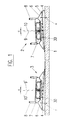
- the two are required on a snowboard Binding devices mounted on the latter so that the two wedge-shaped mounting bases with their tops to each other run inclined so that when the Binding parts with the longitudinal axis of the binding at right angles maximum canting for both along the longitudinal axis of the snowboard Feet is reached, corresponding to a spread standing on the snowboard, with the two perpendicular to the top of the mounting base extending axes approximately in the Hit the hip of a snowboard user.
- the Binding parts carrier relative to the mounting base in the sense is twisted that the respective toe areas closer to the tip the heel is automatically adjusted with the rear binding as well as the toe with the front binding raised, i.e. received a "lift” whereby at the same time the "canting" is reduced.
- This adjustment can be done quickly with the single central screw will. Accordingly, the present binding device is suitable especially for the rental of sports equipment, where regular Settings according to the needs of changing Users are required.
- the binding part carrier for example an elongated one Plate comparable to a binding sole plate, on which binding sled parts are particularly adjustable mounted with Using the central screw directly on the mounting base can be installed adjustable.
- the central screw one with the binding part carrier rotatably connected, on the mounting base arranged rotary position adjustment part perpendicular to the bottom.
- the rotational position adjustment part from a top view generally circular part, also called connecting plate, exist, which has an outer ring gear, which to a Sprocket on the top of the for example also general circular mounting base fits.
- the Teeth be graduated in 3 ° steps.
- the rotary position adjustment part i.e. the connecting plate, can also be used with a scale be provided, so the extent of the rotational position adjustment to be able to check or check in a simple manner.
- the principle of assembly with the only one central, oblique screw maintained.
- the binding part carrier could be in some way, for example with the help of separate bolts, with the rotary position adjustment part once and for all connected non-rotatably, because of the binding adjustment both components with regard to the rotational position be rotated together relative to the mounting base.
- cohesion can be a particularly simple assembly be made possible that the rotational position adjustment part laterally stops on the binding piece carrier for non-rotatable Has connection with this.
- Binding device characterized in that between the binding part carrier and the rotational position adjustment part one intermediate plate also fixed by the central screw is attached, preferably with a rotation lock edge is provided in the screw opening.
- the off-center projections can be simple plug-in projections or also locking projections on a component, e.g. on the intermediate plate, which are in corresponding recesses or depressions on the other part, for example protrude on the rotary position adjustment part and so the exact mutual alignment of the components mentioned before insertion the central screw.
- the intermediate plate made of elastically deformable material exists and thus forms a damping plate.
- the intermediate plate is a wedge pad forms for the binding part carrier.
- the wedge pad can be used a slope in the longitudinal direction and / or a slope in Have transverse direction of the binding part carrier.
- the intermediate plate with the bottom of the Binding part carrier is engaged via projections, e.g. is locked.
- the intermediate plate can, for example have two locking projections, in particular locking tongues, the corresponding, e.g. slit-shaped recesses of the binding piece carrier snap into place for exact alignment to achieve these two components. It can also be used for the assembly of the binding parts carrier together with the intermediate plate as a unit on the mounting base or the rotary position adjustment part be put on.
- the intermediate plate itself support projections extending diametrically away from the screw axis for, in particular, adjustably arranged on the binding part carrier Has binding slide parts. It is further cheap if the support extensions on top with their edges leading snow drainage grooves are formed. These snow drainage grooves therefore lead from a central area the support projections towards the edges thereof, and especially when adjusting the binding slide parts, if these with their undersides over the support extensions can slide, accumulated snow or the like on the latter. pushed and removed by the grooves towards the edges, so that the binding sled parts are still full the support extensions can rest and a flawless Function is made possible.
- binding device quickly and easily, preferred with only one adjusting screw or spindle can.
- binding devices The type in question is normally required, two at a time Binding sled parts, one in the toe area and the other adjustable in the heel area; could think of it become, in a manner known per se with a central spindle opposing threads for the two binding slide parts to use the binding slide parts by turning the spindle in opposite directions along the binding part carrier move.
- a central spindle is, however, according to the Central screw provided according to the invention for the fixation of the binding part carrier is not possible.
- the binding part carrier two by means of a spindle drive in his Binding carriage parts adjustable in the longitudinal direction, and that the spindle drive within the binding part carrier runs off-center at least in sections.
- this Binding device thus becomes the central screw for the assembly is used, "bypassed" by the spindle drive, by this at least in that section where the central Screw is present, off-center in the binding part carrier is arranged.
- two independent adjustment spindles for the binding slide parts are desired, so the binding in the toe area regardless of the binding in the heel area along the binding part carrier adjust and thus better meet the wishes of the To be able to adapt the user, it can be provided that two, preferably axially aligned, spindles, each one for a binding sled part, from the two end faces of the binding part carrier off-center in the binding part carrier extend lengthwise.
- a single spindle for this is provided, which is mounted off-center in the binding parts carrier is at one end from outside the binding part carrier is accessible and in their the two Binding sled parts assigned opposite sections Has thread.
- the two spindles at their inner front ends are provided with keyways or recesses to which non-rotatable coupling of the spindles an optional or releasable coupling wedge is assigned.
- a longitudinal guide for the two binding slide parts is provided. It is also advantageous if the longitudinal guide by a provided in the binding part carrier Longitudinal channel is formed in which a guide projection of the respective Sled part is slidably received. On the other hand In terms of production technology, it is often cheap if the longitudinal guide is formed by a guide rod which in the binding parts carrier is attached and recesses in Guide projections of the two sled parts penetrated.
- FIG. 1 shows schematically at 1 a sports device, here snowboard, indicated, on which two trained in principle the same Binding devices 2, 3 are arranged.
- Each of these binding devices 2, 3 has a wedge-shaped mounting base 4 on, which is firmly attached to the snowboard 1, and on the opposite the bottom and thus the level of the snowboard top Top side 5 inclined (by an angle ⁇ ), a rotational position adjustment part 6 is attached, which in turn with a Binding parts carrier 7 is rotatably connected.
- binding parts 8 (broken off), wherein these binding parts 8, for example, as known per se can be generally bow-shaped (see e.g. also EP 351 289 A or DE 42 09 112 A).
- the respective binding part carrier 7 is with the help of Rotary position adjustment part 6 relative to the fixed mounting base 4 rotatably arranged, being selected in the respective Rotational position can be fixed, as described in more detail below will be explained. So if the binding facilities 2, 3 according to Figure 1, the two binding parts carrier 7 with their Toe areas twisted towards the tip of the snowboard are, for example according to Fig.1 to the right (where it is assumed that the one not illustrated on the right Snowboard tip), so the closer to the snowboard tip located, in Fig.1 right binding device 2 of Toe part of the binding due to the wedge shape of the mounting base 4 raised, but her heel part lowered compared to the shown basic position.
- the one binding device e.g. 2, explained in more detail.
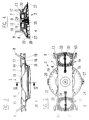
- the binding part carrier 7 an elongated, box-profile-like component with three Longitudinal chambers 11, 12, 13 (see Fig. 4); this binding part carrier 7 carries in its two opposite one another End regions binding slide parts 14 and 15, which are longitudinal of the binding part carrier 7 in order to adapt the binding (see the only partially shown bow-shaped binding parts 8) the respective shoe size can be adjusted as below will be explained in more detail.
- the slide parts 14, 15 are ribbed on their top to form treads formed, as can be seen from the plan view of Figure 2.
- the slide parts 14, 15 can in a conventional manner be educated; in particular, they can each consist of a lower, in cross section general U-shaped part 16, which if necessary with protrusions in the partially at the bottom of the Binding parts carrier 7 open outer longitudinal chambers 11 and 13 respectively engages, and an upper, with the lower part 16 via a Snap or snap connection or a screw connection connected kick part 17 exist, so that the binding part carrier 7 is enclosed like a frame, as is the case with the Fig. 17 to 20 can be seen.
- the upper steps 17 also have a known per se Way laterally grooves or recesses 18 for receiving the bow-like binding parts 8.
- the binding part carrier 7 is non-rotatably seated on the rotational position adjustment part 6, being simple for the non-rotatable connection lateral stops 19 formed on the rotational position adjustment part 6 are.
- the rotational position adjustment part 6 is in more detail on it Top side generally conical, cf. Fig.4, one elongated recess 20 for receiving the binding part carrier 7 is provided.
- the rotational position adjustment part 6 thus has general the shape of a flat truncated cone, being on its circumference with a scale 21 for checking when setting the Rotational position can be provided.
- the Rotary position adjustment part 6 On its underside, a toothed ring or ring 22 on the with a corresponding toothed ring or ring 23 on the Top of the wedge-shaped, also general in plan view circular mounting base 4 cooperates to one gradual rotation of the rotary position adjusting part 6 together Binding parts carrier 7 relative to the mounting base 4, for example in 3 ° steps.
- the individual components of the binding device 2, namely the mounting base 4, the rotational position adjustment part 6 and the Binding parts carrier 7 can (also in the following explained embodiments), for example made of cast aluminum material or preferably consist of GRP polyamide, wherein Recesses, depressions, etc. are provided to save weight can be, like this from the different sectional representations, e.g. Fig.4 (or Fig.6 etc.) is recognizable.
- the Mounting base 4 can also be opposite one another Extensions 26, 27 may be provided, the line or arrow markings for working with scale 21 on the rotary position adjustment part 6 and installation instructions (e.g. "Board Center") to facilitate assembly and adjustment of the binding device Provide 2.
- the central screw 24 can thus easily and quickly connecting the components of the binding device 2 (or 3) can be loosened to the respective rotational position the binding part carrier 7 and thus the foot relative to Snowboard 1 set.
- This central screw 24 forms thus the only mounting element for such Loosening and setting of the binding device must be tightened again, causing the rotational position adjustment the bond can be made in an extremely short time can.
- the mounting base 4 is mounted on the snowboard in one conventional in itself, not illustrated in Figures 2 to 4 Way with the help of screws, cf.
- Position 28 in Figure 5 with the orientation of the mounting base 4th when it is permanently attached to the snowboard 1, as described above in already mentioned in connection with Fig.1, is such that the Mounting base top 5 the maximum slope in the longitudinal direction of the snowboard 1 to the respective other binding device 3 or 2 has gone.
- the binding part carrier 7 could also directly to be mounted on the mounting base 4, it then, for example with a corresponding toothing on its underside would be provided.
- Binding parts carrier 7 in one piece with the adjusting part 6 to manufacture although e.g. for manufacturing reasons usually separate training will be preferred.
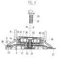
- central screw 24 in a conventional manner, for example with a head 29 conical on the underside (see FIG. Fig.6) or even with a flat head (not shown) can be, i.e. a hemispherical, relatively complex head to be manufactured is not required.
- FIG. 1 and 3 it can also be seen that the rotational position adjustment part 6 diametrically opposite each other Support extensions 30 for supporting the binding slide parts 14, 15 on the cantilevered with its two end regions Binding parts carrier 7 is provided. Sliding more in detail on these support extensions 30 the binding slide parts 14, 15 with their lower parts 16, being between these support extensions 30 and the actual binding parts carrier 7 Space 31 of low height is left, in which the Slide parts 14, 15 adjusted with their lower parts 16 can be.
- each binding slide part 14 or 15 its own, in the longitudinal center of the Binding parts carrier 7 arranged screw 32 for the purpose Adjustment of the slide part 14 or 15 in the longitudinal direction of the Binding parts carrier 7 is assigned, with a corresponding Spindle nut 33 with the respective slide part 14 or 15 is firmly connected.
- Each spindle 32 is in the central longitudinal chamber 12, about 34, rotatably mounted, and from the outside the respective end face of the binding member longitudinal member 7 for a screwdriver accessible so that each slide part 14 or 15 independently of the other along the binding part carrier 7 to be able to adjust the binding.
- 5 to 10 is a modified binding device can be seen, which is currently regarded as particularly preferred becomes.
- 5 to 7 are those components, the components the binding device explained with reference to Figures 1 to 4 correspond with the same reference numerals.
- these components with regard to training, Function and interaction with other components of those correspond to the previously described embodiment, will be below no further explanation, and it will in this regard, reference is made to the above description.
- Fig.5 is indicated by dashed lines that the Mounting base (4 in Fig. 6) provided with four longitudinal slots 35 is to be mounted on the snowboard (1 in Fig.1) with the help of Screws 28, e.g. Phillips mounting screws, under Allow adjustment in a conventional manner.
- Screws 28 e.g. Phillips mounting screws
- Fig. 6 it can also be seen that the binding part carrier 7 - not in contrast to the embodiment according to FIGS. 2 to 4 is in direct contact with the rotary position adjustment part 6, but that between these two components 7, 6 a Intermediate plate 37 is arranged, which is based on the Fig. 8 to 10 will be explained in more detail.
- Intermediate plate 37 which is preferably made of an elastically deformable Plastic material is used to make a damping plate to a small extent (as far as the central screw 24 permits) a relative movement between the binding part carrier 7 and the Rotary position adjustment part 6 enables and thus a damping of Impact caused by snowboarding can cause these blows are not undamped to the foot of the snowboard user be transmitted.
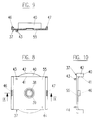
- This damping intermediate plate illustrated in more detail in FIGS. 8 to 10 37 is generally rectangular in plan view, see FIG. Fig.8, and has a central bore 38 for the passage of the central screw 24 (Fig.5 and 6), being in the area of this Bore 38 is also a sealing lip, elastically deformable edge 39 projecting obliquely upwards Protection against rotation of the central screw 24 can be provided; this edge 39 becomes downward when the screw 24 is screwed in pressed; and he thereby holds the screw 24 tight.
- On the opposite long sides (related to the Binding parts carrier 7 according to FIG. 5) is the intermediate plate 37 with upright, one-piece circular segment shaped in plan view Stops 40 provided, facing each other flat inner sides 41 in the assembled state (see FIG.
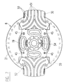
- the intermediate plate 37 is in each other opposite corner areas with locking tongues 43 and 44 provided that serve as an alignment or assembly aid by in corresponding recesses or openings 45 on the Top of the rotary position adjustment part 6 are snapped can (see also Fig. 7).
- the intermediate plate 37 is also on their top with flat locking tongues 46, 47 formed from below into corresponding recesses 48, 49 on the underside of the binding part carrier 7 snap in (see also Fig. 5 also Fig.11) when this binding parts carrier 7 during assembly the rotational position adjustment part 6 and the intermediate plate placed thereon 37 is pressed.
- This also makes the alignment and assembly easier because then the individual central holes in the various components 6, 37, 7 the binding device if they have been arranged one above the other are exact for screwing in the central screw 24 are aligned with each other.
- FIG. 5 also shows a spindle drive arrangement modified compared to FIG. 2, namely with two eccentrically arranged independently rotatable spindles 32 'shown; this Spindles 32 'are in a lateral longitudinal chamber 11 in conventionally rotatably mounted (not shown) and act with spindle nuts 33 'on the binding slide parts 14, 15 together.
- an independent adjustment of the Sled parts 14, 15 is not required, an adjustment with just one operation, with just one Spindle, preferred, cf. also Fig. 17 to 20 and those there shown spindle 62, which also with dashed lines in Fig.5 is indicated.
- the Spindle 62 in the spindle nuts 33 'of the slide parts 14, 15 assigned active sections 62a, 62b in opposite directions Has thread.
- the rotational position adjustment part 6 is also with four arcuate longitudinal slots arranged according to a circle 53 provided which an assembly of this adjustment part 6 enable directly on the snowboard 1, in the event that a Tilting the foot on the snowboard 1 using the wedge-shaped Mounting base 4 is not desired and omitted should.
- 7 is the one for the passage of the central one Screw 24 required central bore 54 shown.
- the intermediate plate 37 can be in addition to or instead of the Damping effect also used to increase the footprint be, depending on the thickness of their actual plate body 55 (see Fig. 9) of the binding part carrier 7 arranged higher or lower can be. In particular, depending on the desired Height of the stand area a correspondingly thick or thin intermediate plate 37, i.e. with a thicker or thinner plate body 55, can be selected and used. In this respect the described modular structure of the binding device 2 (or 3) additionally used advantageously.
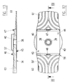
- this wedge pad 56 in the longitudinal direction of the binding part carrier 7 (and thus the foot, not shown) sloping trained, i.e. its top has a slope 57 in Longitudinal direction of the binding part carrier 7.
- the slope 57 in the middle area defines the direct support for the binding part carrier 7.
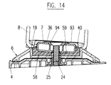
- FIG. 14 corresponds 16 and according to Fig.11 to 13 in principle that according to Fig.8 to 10, with those on the respective intermediate plate 56 and 58 also Locking elements, 43, 44 and 46, 47 are formed, as in the Intermediate plate 37 according to Figures 8 to 10 are present; furthermore are also with the wedge pad intermediate plates 56 and 58 central bores 38 with a sealing lip-like anti-rotation edge 39 provided.
- These extensions 60, 61 are in at their top a way, as already mentioned above in connection with FIG. 7 was explained with the support extensions 30, with Snow drainage grooves 50 'provided.
- the eccentric arrangement is a continuous spindle 62 in connection with a binding slide part 14 can be seen (in the top view according to FIG. 17) only the one effective section 62a of the spindle 62 is shown, the The display should be supplemented in such a way that the other part of the slide 15 is driven by the same spindle 62, for which purpose in the area this other slide part 15 the spindle 62 an opposite Thread compared to the thread in the area of the shown Carriage part 14 must have, cf. also Fig. 5).
- Spindle 62 passing through is in the exemplary embodiment shown arranged in one side longitudinal chamber 11, and it cooperates with a spindle nut 63, which is in one above open slot 64 of an upright tab 65 is inserted; for this purpose, the spindle nut 63 has a circumferential groove 66 into which the tab 65 engages.
- the tab 65 is through one of the Bottom of the lower part 16 of the binding slide 14 (or 15) punched out rag formed from the plane of the bottom was bent up. This tab 65 protrudes through a corresponding one Opening on the underside of the binding part carrier 7 (not shown) in the longitudinal chamber 11, so with the only one To be able to cooperate with spindle 62.
- a comparable Spindle drive with a continuous single eccentric spindle 62, which with a spindle nut 63 or Tab 65 of the slide part 14 (or 15) cooperates, intended; for longitudinal guidance is here in the opposite lateral longitudinal chamber 13 a guide rod 73 is arranged, with a sleeve similar to the spindle nut 63 74 interacts, similar to the spindle nut 63 from above forth inserted into a slot of a guide projection 75 which is similar to the tab 65 by a punched out and bent up flap is formed.
- Fig. 21 is another way to bypass the central bore 76 (for the central screw 24) is provided, namely with an off-center bypass drive rod 77 which in Inside of the one schematically indicated with dash-dotted lines Binding parts carrier 7 at 78 and 79 rotatably mounted is; this drive rod carries 77 bevel gears at both ends 80, 81 with corresponding bevel gears 82, 83 on the inner Interact ends of spindles 84 and 85; these spindles 84 and 85 are arranged centrally in the binding part carrier 7 and for example rotatably supported at 86 or 87; they participate only very schematically drawn spindle nuts 88 and 89 together to this and about this the in Fig.
- FIG. 21 not closer shown slide parts in opposite directions along the binding part carrier 7 to adjust. Again, only one is sufficient Front side 90 of the binding part carrier 7, the one spindle 84 with the help of a screwdriver or the like twist, as indicated by arrow 91 in Fig. 21, so the simultaneous, opposite longitudinal adjustment of both To effect sledge parts.
- FIGS. 18 and 20 the broken lines also show the upper part, the kick part 17, of the binding slide part shown 14 shown, this upper tread part 17 with the lower part 16 on the two long sides (where the lower Part 16 is formed with upstanding walls 92 (see FIG. 17)) is locked (or screwed), so that in this way first the assembly of the lower part 16 on the binding part carrier 7 and then placing and fixing, in particular by snapping the upper part 17 and thus one easy assembly of the binding slide parts 14 and 15 allows becomes.
- the upper step part 17 of each slide part 14 or 15 can also be provided with a separate step covering 6, 11 and 14 at 93 is illustrated.
- FIG. 11 and 14 also show that there in connection with the wedge pads 56 or 58 washer 36 to be used with its axis 24 inclined according to the axis of the central screw Has conical countersink 94, with the washer 36 automatically when tightening the central screw 24 in the correct rotational position, as shown in Figs. 11 and 14, adjusted when the conical, wedge - like underside of the Screw head against the inclined surface of the countersink 94 presses. This means that in this case too hemispherical underside of the screw 24 avoided.
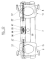
- FIG. 22 shows a further development of the Spindle drive shown in Figure 5, in which two off-center in Binding parts carrier 7 arranged, axially aligned with each other, separate spindles 32 'inside with flanges 95.96 bump into each other.
- the spindles 32 ' axially extending in cross section e.g. rectangular keyways or recesses 97,98 provided, if desired more suitable in cross-section, e.g. rectangular coupling part 99 can be used to the two spindles 32 'for one joint actuation to rotate together.
- the wedge recesses 97.98 can for example, simply be formed by slots that are axially in from the end face of the respective spindle 32 extend the spindle body into it.
- the binding part carrier 7 can be used to insert the wedge 99 for example in the area above the point of the wedge 99 have a closable opening (not shown).
Landscapes
- Connection Of Plates (AREA)
- Diaphragms For Electromechanical Transducers (AREA)
- Non-Reversible Transmitting Devices (AREA)
- Seal Device For Vehicle (AREA)
- Bolts, Nuts, And Washers (AREA)
- Clamps And Clips (AREA)
- Basic Packing Technique (AREA)
Abstract
Description
Claims (23)
- Bindungseinrichtung (2, 3) für Sportgeräte, insbesondere für ein Snowboard (1), mit einem keilförmigen Montagesockel (4), der eine zu seiner Basisebene geneigte Oberseite (5) aufweist, und mit einem gegenüber dem Montagesockel (4) verdrehbar auf diesem angeordneten Bindungsteile-Träger (7), der mittels einer zentralen Schraube (24) am Montagesockel (4) drehfest fixierbar bzw. fixiert ist, dadurch gekennzeichnet, daß die zentrale Schraube (24) zur Basisebene des Montagesockels (4) geneigt, zu dessen Oberseite (5) senkrecht sowie mit ihrer Achse (9) in der Drehachse für die Verdrehung des Bindungsteile-Trägers (7) verläuft .
- Bindungseinrichtung nach Anspruch 1, dadurch gekennzeichnet, daß die zentrale Schraube (24) einen mit dem Bindungsteile-Träger (7) drehfest verbundenen, auf dem Montagesockel (4) angeordneten Drehlagen-Einstellteil (6) senkrecht zu dessen Unterseite durchquert.
- Bindungseinrichtung nach Anspruch 2, dadurch gekennzeichnet, daß der Drehlagen-Einstellteil (6) seitlich am Bindungsteile-Träger (7) anliegende Anschläge (19) zur drehfesten Verbindung mit diesem aufweist.
- Bindungseinrichtung nach Anspruch 2, dadurch gekennzeichnet, daß zwischen dem Bindungsteile-Träger (7) und dem Drehlagen-Einstellteil (6) eine ebenfalls durch die zentrale Schraube (24) fixierte Zwischenplatte (37; 56; 58) angebracht ist, die vorzugsweise mit einem Drehsicherungs-Rand (39) in der Schraubenöffnung (38) versehen ist.
- Bindungseinrichtung nach Anspruch 4, dadurch gekennzeichnet, daß die Zwischenplatte (37; 56; 58) seitlich am Bindungsteile-Träger (7) anliegende Anschläge (40) zur drehfesten Verbindung mit diesem aufweist.
- Bindungseinrichtung nach Anspruch 4 oder 5, dadurch gekennzeichnet, daß die Zwischenplatte (37; 56; 58) mit dem Drehlagen-Einstellteil (6) über außermittige Vorsprünge (43, 44) in Eingriff steht.
- Bindungseinrichtung nach einem der Ansprüche 4 bis 6, dadurch gekennzeichnet, daß die Zwischenplatte (37; 56; 58) aus elastisch verformbarem Material besteht und somit eine Dämpfungsplatte bildet.
- Bindungseinrichtung nach einem der Ansprüche 4 bis 7, dadurch gekennzeichnet, daß die Zwischenplatte (56; 58) eine Keilunterlage für den Bindungsteile-Träger (7) bildet.
- Bindungseinrichtung nach Anspruch 8, dadurch gekennzeichnet, daß die Keilunterlage (56) eine Schräge (57) in Längsrichtung des Bindungsteile-Trägers (7) aufweist.
- Bindungseinrichtung nach Anspruch 8 oder 9, dadurch gekennzeichnet, daß die Keilunterlage (58) eine Schräge (59) in Querrichtung des Bindungsteile-Trägers (7) aufweist.
- Bindungseinrichtung nach einem der Ansprüche 8 bis 10, dadurch gekennzeichnet, daß die zentrale Schraube (24) mit einem konischen Kopf über eine Unterlagscheibe (36), die eine entsprechend der Schräge (57; 59) der Keilunterlage (56; 58) schräg ausgerichtete Ansenkung (94) aufweist, an der Oberseite des Bindungsteile-Trägers (7) anliegt.
- Bindungseinrichtung nach einem der Ansprüche 4 bis 11, dadurch gekennzeichnet, daß die Zwischenplatte (37; 56; 58) mit der Unterseite des Bindungsteile-Trägers (7) über Vorsprünge (46, 47) in Eingriff steht, z.B. verrastet ist.
- Bindungseinrichtung nach einem der Ansprüche 2 bis 12, dadurch gekennzeichnet, daß der Drehlagen-Einstellteil (6) und/oder gegebenenfalls die Zwischenplatte (56; 58) sich bezüglich der Schrauben-Achse (9) diametral weg erstreckende Auflage-Fortsätze (30; 60, 61) für auf dem Bindungsteile-Träger (7) insbesondere verstellbar angeordnete Bindungs-Schlittenteile (14, 15) aufweist.
- Bindungseinrichtung nach Anspruch 13, dadurch gekennzeichnet, daß die Auflage-Fortsätze (30; 60, 61) an ihrer Oberseite mit zu ihren Rändern führenden Schneeableit-Nuten (50; 50') ausgebildet sind.
- Bindungseinrichtung nach einem der Ansprüche 1 bis 14, dadurch gekennzeichnet, daß der Bindungsteile-Träger (7) zwei mittels eines Spindeltriebs (62; 84, 77, 85) in seiner Längsrichtung verstellbare Bindungs-Schlittenteile (14, 15) trägt, und daß der Spindeltrieb innerhalb des Bindungsteile-Trägers (7) zumindest abschnittsweise außermittig verläuft.
- Bindungseinrichtung nach Anspruch 15, dadurch gekennzeichnet, daß sich zwei vorzugsweise, zueinander axial ausgerichtete, Spindeln (32'), je eine für einen Bindungs-Schlittenteil (14, 15), von den beiden Stirnseiten des Bindungsteile-Trägers (7) außermittig in den Bindungsteile-Träger der Länge nach erstrecken.
- Bindungseinrichtung nach Anspruch 16, dadurch gekennzeichnet, daß die beiden Spindeln (32') an ihren innen liegenden stirnseitigen Enden mit Keilnuten oder -ausnehmungen (97,98) versehen sind, denen zur drehfesten Kupplung der Spindeln (32') ein wahlweise einsetzbarer bzw. lösbarer Kupplungs-Keil (99) zugeordnet ist.
- Bindungseinrichtung nach Anspruch 15, dadurch gekennzeichnet, daß eine einzige Spindel (62) im Bindungsteile-Träger (7) außermittig gelagert ist, wobei sie an einem Ende von außerhalb des Bindungsteile-Trägers (7) zugänglich ist und in ihren den beiden Bindungs-Schlittenteilen (14, 15) zugeordneten Wirkabschnitten (62a, 62b) gegenläufige Gewinde aufweist.
- Bindungseinrichtung nach einem der Ansprüche 16 bis 18, dadurch gekennzeichnet, daß auf der der (jeweiligen) Spindel (62) gegenüberliegenden Seite der zentralen Schraube (24) am bzw. im Bindungsteile-Träger (7) eine Längsführung (68) für die beiden Bindungs-Schlittenteile (14, 15) vorgesehen ist.
- Bindungseinrichtung nach Anspruch 19, dadurch gekennzeichnet, daß die Längsführung (68) durch einen im Bindungsteile-Träger (7) vorgesehenen Längskanal (13; 70) gebildet ist, in dem ein Führungsvorsprung (69) des jeweiligen Schlittenteils (14) gleitend aufgenommen ist.
- Bindungseinrichtung nach Anspruch 19, dadurch gekennzeichnet, daß die Längsführung durch eine Führungsstange (73) gebildet ist, die im Bindungsteile-Träger (7) angebracht ist und Ausnehmungen in Führungsvorsprüngen (75) der beiden Schlittenteile (14) durchsetzt.
- Bindungseinrichtung nach Anspruch 20 oder 21, dadurch gekennzeichnet, daß der jeweilige Führungsvorsprung (69; 75) durch eine aus dem allgemein plattenförmigen Schlittenteil (14) ausgestanzte und hochgebogene Lasche gebildet ist.
- Bindungseinrichtung nach Anspruch 15, dadurch gekennzeichnet, daß zwei in der Längsmitte des Bindungsteile-Trägers (7) drehbar gelagerte Spindeln (84, 85), die vor der zentralen Schraube (24) enden, über eine außermittige Umgehungs-Triebstange (77) sowie Getriebeeinrichtungen, wie Kegelrad-Getriebe (80, 82; 81, 83), miteinander gekuppelt sind.
Applications Claiming Priority (3)
| Application Number | Priority Date | Filing Date | Title |
|---|---|---|---|
| AT0016797A AT405246B (de) | 1997-02-03 | 1997-02-03 | Bindungseinrichtung |
| AT167/97 | 1997-02-03 | ||
| AT16797 | 1997-02-03 |
Publications (3)
| Publication Number | Publication Date |
|---|---|
| EP0857498A2 true EP0857498A2 (de) | 1998-08-12 |
| EP0857498A3 EP0857498A3 (de) | 1998-12-16 |
| EP0857498B1 EP0857498B1 (de) | 2001-08-22 |
Family
ID=3483359
Family Applications (1)
| Application Number | Title | Priority Date | Filing Date |
|---|---|---|---|
| EP98890026A Expired - Lifetime EP0857498B1 (de) | 1997-02-03 | 1998-02-02 | Bindungseinrichtung |
Country Status (3)
| Country | Link |
|---|---|
| EP (1) | EP0857498B1 (de) |
| AT (2) | AT405246B (de) |
| DE (1) | DE59801234D1 (de) |
Cited By (1)
| Publication number | Priority date | Publication date | Assignee | Title |
|---|---|---|---|---|
| WO2005014125A1 (de) * | 2003-08-05 | 2005-02-17 | Japana Co., Ltd. | Bindungsanordnung für ski bzw. schneegleitbretter |
Family Cites Families (6)
| Publication number | Priority date | Publication date | Assignee | Title |
|---|---|---|---|---|
| US4867470A (en) * | 1986-10-01 | 1989-09-19 | Sportech, Inc. | Monoski system for snow |
| FR2669237B1 (fr) * | 1990-11-21 | 1993-05-07 | Finiel Remi | Fixations de securite reglables coupees pour surf des neiges. |
| FR2701388B1 (fr) * | 1993-02-16 | 1995-04-28 | Landanger Landos | Elément prothétique pour petites articulations. |
| FR2704439B1 (fr) * | 1993-04-30 | 1995-07-28 | Salomon Sa | Element de retenue d'une chaussure sur une planche de glisse. |
| US5615901A (en) * | 1994-11-02 | 1997-04-01 | Piotrowski; David J. | Adjustable foot equipment |
| DE29510981U1 (de) * | 1995-07-13 | 1995-10-26 | Hlinetzky, Jochen, 71701 Schwieberdingen | Bindung für Snowboards |
-
1997
- 1997-02-03 AT AT0016797A patent/AT405246B/de not_active IP Right Cessation
-
1998
- 1998-02-02 EP EP98890026A patent/EP0857498B1/de not_active Expired - Lifetime
- 1998-02-02 AT AT98890026T patent/ATE204496T1/de not_active IP Right Cessation
- 1998-02-02 DE DE59801234T patent/DE59801234D1/de not_active Expired - Fee Related
Cited By (1)
| Publication number | Priority date | Publication date | Assignee | Title |
|---|---|---|---|---|
| WO2005014125A1 (de) * | 2003-08-05 | 2005-02-17 | Japana Co., Ltd. | Bindungsanordnung für ski bzw. schneegleitbretter |
Also Published As
| Publication number | Publication date |
|---|---|
| DE59801234D1 (de) | 2001-09-27 |
| EP0857498A3 (de) | 1998-12-16 |
| EP0857498B1 (de) | 2001-08-22 |
| ATA16797A (de) | 1998-11-15 |
| AT405246B (de) | 1999-06-25 |
| ATE204496T1 (de) | 2001-09-15 |
Similar Documents
| Publication | Publication Date | Title |
|---|---|---|
| AT411016B (de) | Bindungseinrichtung für sportgeräte, insbesondere für ein snowboard | |
| DE4219036C2 (de) | Snowboardbindung | |
| DE3638887C2 (de) | ||
| EP1053049A1 (de) | Einrichtung zum verbinden eines schneegleiters mit dem schuh eines schneegleiterbenützers | |
| AT408950B (de) | Schi, insbesondere alpinschi | |
| CH681062A5 (de) | ||
| DE3132993A1 (de) | Verbindungsvorrichtung an einem eislaufschuh | |
| DE3135170C2 (de) | ||
| EP2618898B1 (de) | Gleit oder rollsportgerät zum ski oder rollbrett fahren | |
| EP0857498B1 (de) | Bindungseinrichtung | |
| CH688541A5 (de) | Sicherheitsbindung fuer Snowboards. | |
| WO1992019117A2 (de) | Sportschuh | |
| AT516U1 (de) | Befestigungs-system fuer bindungen auf snowboards und skis | |
| DE60021991T2 (de) | Trägerplatte an einem Snowboard | |
| DE19531677C2 (de) | Snowboardbindung | |
| AT502887B1 (de) | Baugruppe für die einstellung einer skibindung und deren fixierung in einer ausgewählten position | |
| WO2001083054A9 (de) | Standplatte für snowboardbindung | |
| DE20311763U1 (de) | Ski mit eingebauter Baugruppe für die Einstellung der Skibindung und deren Fixierung in der ausgewählten Position | |
| DE10335850A1 (de) | Snowboard-Bindung | |
| EP0833575B1 (de) | Skischuh | |
| DE102005056195A1 (de) | Snowboardbindung | |
| DE69723399T2 (de) | Vorrichtung zum Einstellen der Neigung des Schaftes gegenüber der Schale eines Sportschuhs | |
| EP1715929A1 (de) | Auslösbare skibindung | |
| DE29505984U1 (de) | Einspuriger Rollschuh sowie Anbauteil hierfür | |
| WO1998036806A1 (de) | Bindungssystem und bindungsplattenvorrichtung für schneegleiter |
Legal Events
| Date | Code | Title | Description |
|---|---|---|---|
| PUAI | Public reference made under article 153(3) epc to a published international application that has entered the european phase |
Free format text: ORIGINAL CODE: 0009012 |
|
| AK | Designated contracting states |
Kind code of ref document: A2 Designated state(s): AT CH DE FR IT LI |
|
| AX | Request for extension of the european patent |
Free format text: SI |
|
| PUAL | Search report despatched |
Free format text: ORIGINAL CODE: 0009013 |
|
| AK | Designated contracting states |
Kind code of ref document: A3 Designated state(s): AT BE CH DE DK ES FI FR GB GR IE IT LI LU MC NL PT SE |
|
| AX | Request for extension of the european patent |
Free format text: AL;LT;LV;MK;RO;SI |
|
| 17P | Request for examination filed |
Effective date: 19990304 |
|
| AKX | Designation fees paid |
Free format text: AT CH DE FR IT LI |
|
| 17Q | First examination report despatched |
Effective date: 19991227 |
|
| GRAG | Despatch of communication of intention to grant |
Free format text: ORIGINAL CODE: EPIDOS AGRA |
|
| GRAG | Despatch of communication of intention to grant |
Free format text: ORIGINAL CODE: EPIDOS AGRA |
|
| GRAH | Despatch of communication of intention to grant a patent |
Free format text: ORIGINAL CODE: EPIDOS IGRA |
|
| GRAH | Despatch of communication of intention to grant a patent |
Free format text: ORIGINAL CODE: EPIDOS IGRA |
|
| GRAA | (expected) grant |
Free format text: ORIGINAL CODE: 0009210 |
|
| AK | Designated contracting states |
Kind code of ref document: B1 Designated state(s): AT CH DE FR IT LI |
|
| PG25 | Lapsed in a contracting state [announced via postgrant information from national office to epo] |
Ref country code: IT Free format text: LAPSE BECAUSE OF FAILURE TO SUBMIT A TRANSLATION OF THE DESCRIPTION OR TO PAY THE FEE WITHIN THE PRE;WARNING: LAPSES OF ITALIAN PATENTS WITH EFFECTIVE DATE BEFORE 2007 MAY HAVE OCCURRED AT ANY TIME BEFORE 2007. THE CORRECT EFFECTIVE DATE MAY BE DIFFERENT FROM THE ONE RECORDED.SCRIBED TIME-LIMIT Effective date: 20010822 |
|
| REF | Corresponds to: |
Ref document number: 204496 Country of ref document: AT Date of ref document: 20010915 Kind code of ref document: T |
|
| REG | Reference to a national code |
Ref country code: CH Ref legal event code: EP |
|
| REF | Corresponds to: |
Ref document number: 59801234 Country of ref document: DE Date of ref document: 20010927 |
|
| REG | Reference to a national code |
Ref country code: CH Ref legal event code: NV Representative=s name: ABP PATENTMARKETING GMBH |
|
| ET | Fr: translation filed | ||
| PG25 | Lapsed in a contracting state [announced via postgrant information from national office to epo] |
Ref country code: AT Free format text: LAPSE BECAUSE OF NON-PAYMENT OF DUE FEES Effective date: 20020202 |
|
| PG25 | Lapsed in a contracting state [announced via postgrant information from national office to epo] |
Ref country code: LI Free format text: LAPSE BECAUSE OF NON-PAYMENT OF DUE FEES Effective date: 20020228 Ref country code: CH Free format text: LAPSE BECAUSE OF NON-PAYMENT OF DUE FEES Effective date: 20020228 |
|
| PLBE | No opposition filed within time limit |
Free format text: ORIGINAL CODE: 0009261 |
|
| STAA | Information on the status of an ep patent application or granted ep patent |
Free format text: STATUS: NO OPPOSITION FILED WITHIN TIME LIMIT |
|
| 26N | No opposition filed | ||
| PG25 | Lapsed in a contracting state [announced via postgrant information from national office to epo] |
Ref country code: DE Free format text: LAPSE BECAUSE OF NON-PAYMENT OF DUE FEES Effective date: 20020903 |
|
| REG | Reference to a national code |
Ref country code: CH Ref legal event code: PL |
|
| PG25 | Lapsed in a contracting state [announced via postgrant information from national office to epo] |
Ref country code: FR Free format text: LAPSE BECAUSE OF NON-PAYMENT OF DUE FEES Effective date: 20021031 |
|
| REG | Reference to a national code |
Ref country code: FR Ref legal event code: ST |