EP0860290B1 - Bogenfördergerät und Bilderzeugungsgerät - Google Patents
Bogenfördergerät und Bilderzeugungsgerät Download PDFInfo
- Publication number
- EP0860290B1 EP0860290B1 EP98102898A EP98102898A EP0860290B1 EP 0860290 B1 EP0860290 B1 EP 0860290B1 EP 98102898 A EP98102898 A EP 98102898A EP 98102898 A EP98102898 A EP 98102898A EP 0860290 B1 EP0860290 B1 EP 0860290B1
- Authority
- EP
- European Patent Office
- Prior art keywords
- sheet
- conveying
- convey
- processing
- roller
- Prior art date
- Legal status (The legal status is an assumption and is not a legal conclusion. Google has not performed a legal analysis and makes no representation as to the accuracy of the status listed.)
- Expired - Lifetime
Links
- 229920006254 polymer film Polymers 0.000 claims description 7
- 239000011248 coating agent Substances 0.000 claims description 6
- 238000000576 coating method Methods 0.000 claims description 6
- 238000010438 heat treatment Methods 0.000 claims description 6
- 230000000694 effects Effects 0.000 claims description 5
- 239000000758 substrate Substances 0.000 claims description 5
- 238000011144 upstream manufacturing Methods 0.000 claims description 5
- 238000007599 discharging Methods 0.000 claims description 3
- 230000002093 peripheral effect Effects 0.000 claims 1
- 230000015572 biosynthetic process Effects 0.000 description 16
- 239000000463 material Substances 0.000 description 6
- 239000004816 latex Substances 0.000 description 5
- 229920000126 latex Polymers 0.000 description 5
- 238000010276 construction Methods 0.000 description 4
- 238000003780 insertion Methods 0.000 description 3
- 230000037431 insertion Effects 0.000 description 3
- -1 polyethylene terephthalate Polymers 0.000 description 3
- 229920000139 polyethylene terephthalate Polymers 0.000 description 2
- 239000005020 polyethylene terephthalate Substances 0.000 description 2
- 230000001360 synchronised effect Effects 0.000 description 2
- 239000004698 Polyethylene Substances 0.000 description 1
- 239000012190 activator Substances 0.000 description 1
- QVQLCTNNEUAWMS-UHFFFAOYSA-N barium oxide Chemical compound [Ba]=O QVQLCTNNEUAWMS-UHFFFAOYSA-N 0.000 description 1
- 229910001864 baryta Inorganic materials 0.000 description 1
- 239000011230 binding agent Substances 0.000 description 1
- 229920006317 cationic polymer Polymers 0.000 description 1
- 238000004040 coloring Methods 0.000 description 1
- 238000001816 cooling Methods 0.000 description 1
- 229920000554 ionomer Polymers 0.000 description 1
- 238000000034 method Methods 0.000 description 1
- 239000002245 particle Substances 0.000 description 1
- 229920000573 polyethylene Polymers 0.000 description 1
- 229920000642 polymer Polymers 0.000 description 1
- 229920005989 resin Polymers 0.000 description 1
- 239000011347 resin Substances 0.000 description 1
- 238000004904 shortening Methods 0.000 description 1
- 229920003002 synthetic resin Polymers 0.000 description 1
Images


Classifications
-
- B—PERFORMING OPERATIONS; TRANSPORTING
- B41—PRINTING; LINING MACHINES; TYPEWRITERS; STAMPS
- B41J—TYPEWRITERS; SELECTIVE PRINTING MECHANISMS, i.e. MECHANISMS PRINTING OTHERWISE THAN FROM A FORME; CORRECTION OF TYPOGRAPHICAL ERRORS
- B41J13/00—Devices or arrangements of selective printing mechanisms, e.g. ink-jet printers or thermal printers, specially adapted for supporting or handling copy material in short lengths, e.g. sheets
- B41J13/0009—Devices or arrangements of selective printing mechanisms, e.g. ink-jet printers or thermal printers, specially adapted for supporting or handling copy material in short lengths, e.g. sheets control of the transport of the copy material
- B41J13/0045—Devices or arrangements of selective printing mechanisms, e.g. ink-jet printers or thermal printers, specially adapted for supporting or handling copy material in short lengths, e.g. sheets control of the transport of the copy material concerning sheet refeed sections of automatic paper handling systems, e.g. intermediate stackers
-
- B—PERFORMING OPERATIONS; TRANSPORTING
- B41—PRINTING; LINING MACHINES; TYPEWRITERS; STAMPS
- B41J—TYPEWRITERS; SELECTIVE PRINTING MECHANISMS, i.e. MECHANISMS PRINTING OTHERWISE THAN FROM A FORME; CORRECTION OF TYPOGRAPHICAL ERRORS
- B41J13/00—Devices or arrangements of selective printing mechanisms, e.g. ink-jet printers or thermal printers, specially adapted for supporting or handling copy material in short lengths, e.g. sheets
- B41J13/009—Diverting sheets at a section where at least two sheet conveying paths converge, e.g. by a movable switching guide that blocks access to one conveying path and guides the sheet to another path, e.g. when a sheet conveying direction is reversed after printing on the front of the sheet has been finished and the sheet is guided to a sheet turning path for printing on the back
-
- B—PERFORMING OPERATIONS; TRANSPORTING
- B41—PRINTING; LINING MACHINES; TYPEWRITERS; STAMPS
- B41J—TYPEWRITERS; SELECTIVE PRINTING MECHANISMS, i.e. MECHANISMS PRINTING OTHERWISE THAN FROM A FORME; CORRECTION OF TYPOGRAPHICAL ERRORS
- B41J13/00—Devices or arrangements of selective printing mechanisms, e.g. ink-jet printers or thermal printers, specially adapted for supporting or handling copy material in short lengths, e.g. sheets
- B41J13/02—Rollers
Definitions
- the present invention relates to a conveying apparatus disposed between first and second processing portions having independent conveying systems, and more particularly, it relates to a sheet conveying apparatus disposed between an image forming means and a fixing means.
- an image forming apparatus having an image forming means as a first processing portion and a fixing means as a second processing portion.
- a sheet in which cationic polymer (PVA) as an ink holding layer is coated on a RET (polyethylene terephthalate) film as a substrate and a white ink transporting layer is coated on the ink holding layer is used as a recording material.
- the ink transporting layer is obtained by mixing activator and polyethylene particles by using ionomer as binder.
- An image is recorded by an ink jet recording head (image forming means) of line type covering the entire width of the recording material, and the ink transporting layer is melted by a pair of pressure/heat rollers (fixing means) disposed adjacent to and at a downstream side of the recording head to make the transporting layer smooth and transparent, thereby forming a transparent smooth layer coating the imaged surface of the recording material.
- the present invention aims to eliminate the above-mentioned conventional drawback, and an object of the present invention is to provide a compact conveying apparatus which is disposed between the processing portions and which can cope with recording materials having various sizes without interference between conveying systems of the two processing portions.
- a conveying apparatus disposed between first and second processing portions having independent conveying systems and including a convey path for feeding a processed medium conveyed from the first processing portion to the second processing portion, in which the convey path is divided into first and second convey path portions, and an escape portion for temporarily escaping the processed medium conveyed in the first convey path portion and for conveying the processed medium to the second convey path portion with a tail end of the processed medium facing forwardly is provided between the first and second convey path portions, and there is provided a conveying means which does not apply any load to the processed medium when the processed medium is being conveyed by the conveying system of the first processing portion and starts to apply a conveying force to the processed medium after the conveyance of the processed medium effected by the conveying system of the first processing portion is finished.
- processing means the fact that the processed medium (sheet) is subjected to various phenomena for changing quality of the sheet.
- sheet means all of sheet-shaped processed media, as well as a cut sheet and an OHP sheet.
- the conveying means starts to convey the processed medium in a direction along which the tip end of the processed medium is escaped. After the processed medium is conveyed until the tail end of the processed medium reaches the vicinity of the escape portion, the conveying means is rotated reversely so that the processed medium starts to be conveyed toward the second convey path portion with the tail end of the processed medium facing forwardly.
- the conveying means may be provided at the escape portion.
- the convey path is bent around the escape portion.
- the conveying means comprises a roller shiftable in an up-and-down direction.
- the conveying means may comprise a D-cut roller.
- the D-cut roller is a roller in which a part of periphery of a roller is cut away.
- a shutter for directing the tail end of the processed medium conveyed from the first convey path portion to the second convey path portion.
- the convey means may comprise a vertically shiftable roller provided in the first convey path portion, a D-cut roller provided at the escape portion, first and second sheet (processed medium) detecting means provided in the first convey path portion, and convey rollers provided in the second convey path portion and may be designed so that the above elements are disposed to satisfy a relation "L3 ⁇ L1 ⁇ L2 ⁇ L" when a length of an arc of the D-cut roller is L, a distance from a nip point of the vertically shiftable roller to the D-cut roller is L1, a distance from the first sheet detecting means to the D-cut roller is L2 and a distance from the D-cut roller to an most upstream convey roller (among the convey rollers) is L3, and the second sheet detecting means is disposed immediately in front of the escape portion.
- the processed medium treated by the above-mentioned conveying apparatus is a sheet and the first processing portion is an image forming means.
- the "sheet” means all of sheet-shaped processed media, as well as a cut sheet and an OHP sheet.
- the second processing portion may be a fixing means.
- At least one roller having a driving force may be disposed in the second convey path portion between the escape portion and the fixing means, and such a roller may be a one-way roller driven by a conveying force of the fixing means not to generate slip between the sheet and the roller.
- a plurality of rollers may be provided in the second convey path portion, and, by a conveying force of a most downstream roller among the rollers contacted with the sheet, the other rollers may be rotatingly driven.
- a temperature of a surface of the sheet may be increased before the fixing by fixing heat generated by the fixing means.
- the present invention further provides an image forming apparatus comprising the above-mentioned sheet conveying apparatus, an image forming means as the first processing portion, and a fixing means as the second processing portion.
- the present invention also provides an image forming apparatus for forming an image on a processed medium obtained by coating ink permeable polymer film on a substrate, wherein, after the image is formed on the processed medium by the image forming means in an ink jet manner, the processed medium is thermally treated by the fixing means to make the polymer film finer.
- FIG. 1 to 9 An arrangement in which a sheet conveying apparatus according to a first embodiment of the present invention is applied to an image forming apparatus is shown in Figs. 1 to 9.
- Figs. 1 to 5 are enlarged views for explaining an operation of the sheet conveying apparatus
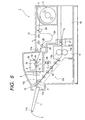
- Fig. 6 is a sectional view of the image forming apparatus
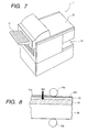
- Fig. 7 is a perspective view of the image forming apparatus
- Fig. 8 is a sectional view of a sheet used in the sheet conveying apparatus
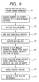
- Fig. 9 is a flow chart showing an operation sequence of the sheet conveying apparatus.
- the image forming apparatus mainly treats special media and has various features corresponding to features of the media (sheets), a construction of the sheet will firstly be described.
- Fig. 8 shows the sheet pinched between fixing rollers.
- the sheet is constituted by four layers, i.e., a latex layer (ink permeable polymer film) 41a, a coloring layer 40 mainly absorbing ink, a substrate 39 formed from a RET (polyethylene terephthalate) sheet or a baryta sheet, and a back coating 38.
- a latex layer ink permeable polymer film
- a coloring layer 40 mainly absorbing ink
- a substrate 39 formed from a RET (polyethylene terephthalate) sheet or a baryta sheet a back coating 38.
- RET polyethylene terephthalate
- the latex layer 41a having the noticeable feature is melted by heat (110-180°C) of a fixing roller 14a and is changed to a transparent laminated layer 41b after cooling.
- gloss, water-resistance and anti-weather of an image are greatly improved.
- an image forming apparatus 1 comprises a sheet supplying system, an image forming system as a first processing portion, a conveying system (switch-back conveying system) as a convey path or a convey means including an escape portion, and a fixing system as a second processing portion.
- the image forming system and the fixing system are disposed side by side in a vertical direction so that sheet convey path portions are disposed side by side in a vertical direction.
- the sheet supplying system includes an upper lid 21 which can be opened and closed around a hinge 21a so that a cartridge 3 containing a roll-shaped sheet 2 can be incorporated into the sheet supplying system, a pair of pick-up rollers 20, 20a for drawing the sheet from the cartridge 3, and a pair of pulling rollers 22, 22a for sending the sheet to the image forming system.
- a loop having a substantially constant amount is formed in the sheet between the pair of pick-up rollers 20, 20a and the pair of pulling rollers 22, 22a.
- a nip between the paired pulling rollers 22 and 22a can be released by a cam (not shown).
- the image forming system as the first processing portion mainly includes an image forming portion 5 of ink jet type, a line feed roller (LF roller) 6 which is a conveying system as a second conveying means for effecting conveyance of the sheet during image formation, an LF driven roller 6a, a spurred roller 7a, and a downstream LF roller 7 so that the sheet conveyed from the sheet supplying system can be conveyed intermittently by a predetermined length Li (about 10 mm).
- the image forming system is constituted by the image forming portion 5, LF roller 6, LF driven roller 6a, downstream LF roller 7 and spurred roller 7a. Further, a sheet insertion opening 25 and an open/close switch (not shown) for the sheet insertion opening are provided to permit a sheet manual insertion.
- a cutter 8 for cutting the sheet to a desired length is disposed between the image forming system and the switch-back conveying system.
- the switch-back conveying system comprises a sheet conveying apparatus for conveying the sheet between the image forming system and the fixing system which are not synchronous with each other mechanically and are not interfered with each other. Further, there are provided a shutter 9, a D-cut roller 10 as a conveying means, and a plurality of pairs of convey rollers 12 disposed along a conveying direction.
- the convey path is divided into a first convey path portion 13a and a second convey path portion 13b before and after the D-cut roller 10.
- An escape portion 11b is provided so that the sheet conveyed through the first convey path portion is temporarily escaped from the convey path to a discharge tray 11 as a guide without fail, and the entire convey path is bent at the escape portion 11b.
- Lower rollers of the plural pairs of rollers 12 are rotatably mounted on an open/close door (not shown) so that a jammed sheet can easily be removed.
- the fixing system includes a heating means or fixing means 14 comprised of a pair of fixing rollers including a heat roller 14a and a pressure roller 14b.
- the loop 24 must be maintained during the image formation.
- a look sensor (not shown) associated with the pair of pick-up rollers 20, 20a.
- the image forming portion 5 serves to convey the sheet pinched between a platen (not shown) and a sheet hold-down member (not shown) intermittently in the conveying direction by the predetermined length (about 10 mm).
- the image forming portion 5 utilizes cyan color ink, light cyan color ink, magenta color ink, light magenta color ink, yellow color ink and black color ink to achieve high quality image formation.
- the image forming portion 5 includes a recording head 5a having six kinds of nozzles for discharging the cyan color ink, light cyan color ink, magenta color ink, light magenta color ink, yellow color ink and black color ink.
- a carriage 5b on which the recording head 5a is mounted is shifted along a carriage guide 5c in a direction perpendicular to the sheet conveying direction (scanning) and ink is discharged from the recording head 5a integrally shifted together with the carriage 5b in response to image data, thereby forming an image.
- the carriage 5b is shifted by a drive means (not shown).
- the carriage 5b and the drive means constitute a shift means.
- a nip roller 16 provided in the first convey path portion 13a is supported on a free end of an arm 16c rockable around a shaft 16b.
- the nip roller 16 provided in the first convey path portion 13a is spaced apart from a driving roller 16a so that the sheet is not pinched between these rollers. Further, the D-cut roller is normally positioned so that a cut-out portion 10c (of the D-cut roller) having a smaller radius is opposed to a driven roller 10a not to pinch the sheet therebetween. The reason is that any conveying load is not applied to the sheet during the image formation to improve the conveying accuracy of the LF roller 6 and the downstream LF roller 7.
- the tip end of the sheet is directed onto the discharge tray 11.
- the sheet is conveyed by the conveying system of the image forming system until a portion of the sheet to be a tail end after cutting reaches the position of the cutter 8 to obtain a cut sheet having a desired length. After the sheet is pinched by the switch-back conveying systems so that the sheet is not dropped out of the apparatus, the sheet is cut by the cutter 8.
- the remaining sheet portion is returned to a position where the tip end of the sheet is positioned at the image formation start position, thereby preparing for next image formation.
- the shutter (guide means) 9 is switched and the D-cut roller 10 is rotated reversely.
- the sheet is directed to the second convey path portion 13b.
- the plurality of pair of convey rollers 12 are disposed side by side and are rotated at the same speeds so that the sheet is conveyed with the tail end thereof facing forwardly.
- Each of these paired convey rollers is constituted by a one-way roller so that, if the pairs of convey rollers 12 are rotated at different speeds for some reason, the rotational speed of the convey rollers is changed to become the same as that of a most downstream pair of convey rollers among the pairs of convey rollers contacted with the sheet and the other convey rollers are rotatingly driven in synchronous with the most downstream pair of convey rollers. Accordingly, any load is not applied to the sheet and no slip is generated between the sheet and the rollers.
- Lower rollers of the plural pairs of convey rollers 12 are biased by springs (not shown) toward the corresponding lower rollers to adjust nips between the upper rollers and the lower rollers, thereby preventing the latex layer of the sheet from being damaged.
- the sheet passed through the second convey path portion is transferred to the fixing system.
- the driving of the pairs of convey rollers 12 is stopped so that these rollers are rotatingly driven by the conveying force of the fixing rollers 14a, 14b.
- the latex layer formed on the surface of the sheet is melted by the heat (110-180°C) of the fixing roller. After cooled, the latex layer becomes a transparent laminated layer (Fig. 8). Further, the heat generated in the fixing system is transmitted to the sheet existed in the second convey path portion 13b by means of a fan 26, thereby achieving the pre-heat effect.
- a curl formed in the sheet left the fixing system is corrected by an uncurling means or curl correcting means 27 and then is discharged to a discharge portion 15.
- the switch-back conveying system is a sheet conveying apparatus in which the sheet conveyed from the image forming means is switched back to convey it to the fixing means and which comprises the shutter 9, D-cut roller 10, discharge tray 11, convey rollers 12, vertically shiftable nip roller 16, first sheet detecting means 30 and second sheet detecting means 31.
- the reference numeral 12a denotes a most upstream convey roller (nearest to the D-cut roller) among the convey rollers 12.
- a control means controls the cutter 8, a drive means such as a motor and a clutch for shifting the nip roller 16 in the vertical direction, a drive means such as a motor and a clutch for rotating the driving roller 16a, a drive means such as a motor and a clutch for rotating the D-cut roller 10, and a solenoid for shifting the shutter 9.
- the control means also controls motors for driving the LF roller 6 and the downstream LF roller 7, a drive means for shifting the carriage 5b and a drive means for discharging the ink from the recording head 5a.
- the sheet conveying apparatus is firstly positioned in a condition shown in Fig. 1. That is to say, the nip roller 16 is waiting at the upper position to be spaced apart from the driving roller 16a, with the result that the sheet is not pinched between the rollers 16 and 16a. Further, the cut-out portion 10c of the D-cut roller 10 having the small radius is opposed to the driven roller 10a so that the sheet is not pinched between the rollers 10 and 10a. The portion of the sheet on which the image was formed is conveyed toward the discharge tray 11 by the LF roller 6 and the downstream LF roller 7 without applying any load from the rollers 16, 16a, 10, 10a to the sheet portion.
- the guide 32 disposed below the D-cut roller 10 is lowered together with the driven roller 10a by the cam (not shown) to be brought to a position shown by the broken line in Fig. 1, thereby providing, below the D-cut roller 10, an adequate space through which the sheet is discharged onto the discharge tray 11.
- the tip end of the sheet is suspended from the discharge tray 11.
- the reason why the sheet is pinched between the nip roller 16 and the driven roller 16a before the sheet is cut by the cutter 8 is that the sheet is prevented from dropping from the discharge tray by the weight of the sheet itself upon cutting the sheet.
- the sheet can be pinched between the D-cut roller 10 and the driven roller 10a for preventing the sheet from being dropped, due to the design limitation, since a distance between the cutter 8 and the D-cut roller 10 should be longer than a smallest length (for a post card) of the sheet, in the illustrated embodiment, the nip roller 16 is provided to convey such a sheet to the D-cut roller 10.
- a roller 11a or member having an arch-like curvature is provided at a tip end of the discharge tray to improve the sliding effect of the sheet on the discharge tray.
- the driving roller 16a starts to be rotate to convey the sheet in a first direction (flow F5). Thereafter, when the tail end of the sheet is detected by the first sheet detecting means 30 (flow F6), the D-cut roller starts to rotate normally (in a clockwise direction in Fig. 2). At the same time when the rotation of the D-cut roller 10 is started, the guide 32 is shifted upwardly to the position shown by the solid line to form the nip between the D-cut roller 10 and the driven roller 10a of the guide 32.
- the tail end of the sheet is directed, by the shutter 9, to the most upstream convey roller 12a among the convey rollers 12, with the result that the sheet is conveyed toward the fixing means by the convey rollers.
- the arrangement of various elements or members is predetermined.
- a length of an arc of the D-cut roller 10 is L
- a distance from a nip point of the nip roller 16 to the D-cut roller 10 is L1
- a distance from the first sheet detecting means 30 to the D-cut roller 10 is L2
- a distance from the D-cut roller 10 to the convey rollers 12a is L3
- the elements must be arranged to satisfy a relation "L3 ⁇ L1 ⁇ L2 ⁇ L".
- the image formation can be effected regarding the sheet having greater length.
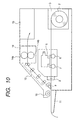
- Fig. 10 shows a case where a sheet conveying apparatus according to a second embodiment of the present invention is applied to an image forming apparatus.
- the second convey path portion 13b is disposed below the first convey path portion 13a was explained in the first embodiment, in the second embodiment, the second convey path portion is disposed above the first convey path portion 13a. Since the other functions and effects are the same as those in the first embodiment, the same elements are designated by the same reference numerals and explanation thereof will be omitted.
- the sheet conveying apparatus can be applied to any apparatuses so long as the sheet conveying apparatus is disposed between two processing portions having independent conveying systems.
- sensors of light permeable type may be used or mechanical sensors may be used.
- the mechanical sensor is used as the second sheet detecting means, it is desirable that the operation of the sensor does not interfere with the shutter, and, it is preferable that such a mechanical sensor is provided integrally with the shutter 9.
- the waiting time is controlled on the basis of material of the sheet and/or an amount of ink used in the image formation.
- the D-cut roller may be disposed nearer to the discharge roller, and two or more nip rollers 16 may be provided.
- the present invention provides the sheet conveying apparatus disposed between the first and second processing portions having the independent convey systems and including the convey path for feeding the processed medium conveyed from the first processing portion to the second processing portion, and wherein the convey path includes the first convey path portion, second convey path portion, and escape portion for temporarily escaping the processed medium from the first convey path portion and for conveying the processed medium to the second convey path portion with the tail end of the processed medium facing forwardly, and further wherein the convey path is provided with the convey means in which any load is not applied to the processed medium during the conveyance of the processed medium in the first processing portion and thereafter the conveying force is applied to the processed medium.
- the processed media having various sizes can be conveyed without making the apparatus bulky and preventing the interference between the two processing portions.
- the present invention is not limited to such an example, but, may be applied to any sheet processing apparatus in which treatment is effected in first and second processing portions.
- the ink permeable layer may be formed from a porous polymer layer (particularly, a resin porous layer).
- a transparent polymer (resin) layer is formed on the imaged surface of the sheet.
- a convey path is divided into a first convey path portion 13a and a second convey path portion 13b, a discharge tray 11 as an escape portion for temporarily escaping a sheet conveyed in the first convey path portion 13a and for conveying the sheet to the second convey path portion 13b with a tail end of the sheet facing forwardly is provided between the first and second convey path portions, and there are provided nip roller 16 and a D-cut roller 10 as a conveying means which does not apply any load to the sheet when the sheet is being conveyed by a conveying system of an image forming means (first processing portion) and which starts to apply a conveying force to the sheet after conveyance of the sheet effected by the conveying system of the first processing portion is finished.
Landscapes
- Delivering By Means Of Belts And Rollers (AREA)
Claims (31)
- Fördervorrichtung, die zwischen einem ersten Bearbeitungsabschnitt und einem zweiten Bearbeitungsabschnitt angeordnet ist, die jeweils ein unabhängiges Fördersystem haben, und die eine Förderbahn für ein Fördern eines von dem ersten Bearbeitungsabschnitt zu dem zweiten Bearbeitungsabschnitt beförderten bearbeiteten Mediums aufweist, wobei die Förderbahn in einen ersten Förderbahnabschnitt und einen zweiten Förderbahnabschnitt geteilt ist;
einem Auslassabschnitt für ein zeitweiliges Auslassen des in dem ersten Förderbahnabschnitt geförderten bearbeiteten Mediums und zum Fördern des bearbeiteten Medium zu dem zweiten Förderbahnabschnitt, wobei ein Endstück des bearbeiteten Mediums nach vorn weist, der zwischen dem ersten und dem zweiten Förderbahnabschnitt vorgesehen ist; und
einer Fördereinrichtung, die keine Last auf das bearbeitete Medium aufbringt, wenn das bearbeitete Medium gerade durch das Fördersystem des ersten Bearbeitungsabschnitts gefördert wird, und die beginnt, eine Förderkraft auf das bearbeitete Medium aufzubringen, nachdem eine durch das Fördersystem des ersten Bearbeitungsabschnitts bewirkte Förderung des bearbeiteten Medium beendet ist. - Fördervorrichtung gemäss Anspruch 1, wobei die Fördereinrichtung an dem Auslassabschnitt vorgesehen ist.
- Fördervorrichtung gemäss Anspruch 1 oder 2, wobei die Förderbahn an dem Auslassabschnitt gebogen ist.
- Fördervorrichtung gemäss Anspruch 1, 2 oder 3, wobei die Fördereinrichtung eine in eine nach oben und unten gerichtete Richtung verschiebbare Walze aufweist.
- Fördervorrichtung gemäss Anspruch 1, 2, 3, oder 4, wobei die Fördereinrichtung eine D-Schnittwalze aufweist.
- Fördervorrichtung gemäss Anspruch 1, 2, 3, 4 oder 5, des weiteren mit einem Schließer zum Richten des Endstücks des von dem ersten Förderbahnabschnitt zu dem zweiten Förderbahnabschnitt geförderten bearbeiteten Mediums.
- Fördervorrichtung gemäss einem der Ansprüche 1 bis 6, wobei:wobei der erste Förderbahnabschnitt eine erste Erfassungseinrichtung des bearbeiteten Mediums und eine zweite Erfassungseinrichtung des bearbeiteten Mediums aufweist; unddie Fördereinrichtung eine an dem ersten Förderbahnabschnitt vorgesehene vertikal verschiebbare Walze und eine an dem Auslassabschnitt vorgesehene D-Schnittwalze aufweist;
wobei der zweite Förderbahnabschnitt Förderwalzen aufweist;
wobei die vorstehend genannten Elemente angeordnet sind, um eine Beziehung "L3 < L1 < L2 < L" zu erfüllen, wenn eine Länge eines Bogens der D-Schnittwalze L, ein Abstand zwischen einem Klemmpunkt der vertikal verschiebbaren Walze zu der D-Schnittwalze L1, ein Abstand von der ersten Erfassungseinrichtung des bearbeiteten Mediums zu der D-Schnittwalze L2 und ein Abstand von der D-Schnittwalze zu der am weitesten stromaufwärts gelegenen Förderwalze aus den Förderwalzen L3 beträgt;
und wobei die zweite Erfassungseinrichtung des bearbeiteten Mediums unmittelbar vor dem Auslassabschnitt angeordnet ist. - Fördervorrichtung gemäss einem der Ansprüche 1 bis 7, wobei das bearbeitete Medium ein Blatt ist und der erste Bearbeitungsabschnitt eine Bildausbildungseinrichtung ist.
- Fördervorrichtung gemäss einem der Ansprüche 1 bis 7, wobei das bearbeitete Medium ein Blatt ist und der zweite Bearbeitungsabschnitt eine Fixiereinrichtung ist.
- Blattfördervorrichtung gemäss Anspruch 9, wobei zumindest eine Walze, die eine Antriebskraft hat, an dem zweiten Förderbahnabschnitt zwischen dem Auslassabschnitt und der Fixiereinrichtung angeordnet ist und die Walze eine Einwegwalze ist, die durch eine Förderkraft der Fixiereinrichtung angetrieben ist, um ein Durchrutschen zwischen der Blattfläche und der Walze nicht zu erzeugen.
- Blattfördervorrichtung gemäss Anspruch 10, wobei eine Vielzahl von Walzen vorgesehen ist und durch eine Förderkraft einer am weitesten stromabwärts gelegenen Walze aus den Walzen, die mit dem Blatt in Berührung stehen, die anderen stromaufwärtigen Walzen drehbar angetrieben werden.
- Blattfördervorrichtung gemäss Anspruch 9, 10 oder 11, wobei eine Temperatur einer Fläche des Blattes vor dem Fixieren durch Aufbringen einer durch die Fixiereinrichtung erzeugten Wärme auf den zweiten Förderbahnabschnitt erhöht wird.
- Bildausbildungsvorrichtung mit:einer Blattfördervorrichtung gemäss einer der Ansprüche 9 bis 12;einer Bildausbildungseinrichtung als den ersten Bearbeitungsabschnitt; undeiner Fixiereinrichtung als den zweiten Bearbeitungsabschnitt.
- Bildausbildungsvorrichtung gemäss Anspruch 13, wobei ein Bild an einem Blatt ausgebildet wird, das durch Beschichten eines für Tinte permeablen Polymerfilms an einem Substrat erhalten wird, wobei, nachdem das Bild an dem Blatt durch die Bildausbildungseinrichtung auf eine Tintenstrahlart ausgebildet ist, das Blatt thermisch durch die Fixiereinrichtung behandelt wird, um den Polymerfilm feiner zu machen.
- Blattbearbeitungsvorrichtung, die einen ersten Bearbeitungsabschnitt zum Bearbeiten eines Blattes, während sie das Blatt fördert, und einen zweiten Bearbeitungsabschnitt zum Bearbeiten des Blattes hat, während das durch den ersten Bearbeitungsabschnitt bearbeitete Blatt gefördert wird, mit:einer Fördereinrichtung für ein Fördern des Blattes, das durch den ersten Bearbeitungsabschnitt bearbeitet ist, in einer ersten vorbestimmten Richtung und für ein Fördern des Blattes in einer zweiten Richtung, die entgegengesetzt zu der ersten Richtung ist, nachdem ein Endstück des Blattes durch den ersten Bearbeitungsabschnitt hindurch tritt; undeiner Führungseinrichtung für ein Führen des Blattes, das durch die Fördereinrichtung in der ersten Richtung zu dem zweiten Bearbeitungsabschnitt gefördert wird.
- Blattbearbeitungsvorrichtung gemäss Anspruch 15, des weiteren mit einer Führung zum Führen des Blattes, das durch die Fördereinrichtung gerade gefördert wird, und wobei ein Blatt, das eine Länge hat, die größer als eine vorbestimmte Länge ist, die Führung überschreitet und von der Führung aufgehängt bzw. getragen wird, wenn das Blatt durch die Fördereinrichtung in der ersten Richtung gefördert wird.
- Blattbearbeitungsvorrichtung gemäss Anspruch 15, wobei der erste und der zweite Bearbeitungsabschnitt in einer Relation nach oben und unten angeordnet sind.
- Blattbearbeitungsvorrichtung gemäss Anspruch 15, wobei die Fördereinrichtung das Blatt nicht klemmt, wenn das Blatt durch den ersten Bearbeitungsabschnitt gerade bearbeitet wird, und das Blatt klemmt, nachdem die durch den ersten Bearbeitungsabschnitt bewirkte Bearbeitung des Blattes beendet ist.
- Blattbearbeitungsvorrichtung gemäss Anspruch 18, wobei die Fördereinrichtung ein Paar Förderwalzen aufweist, die voneinander trennbar sind.
- Blattbearbeitungsvorrichtung gemäss Anspruch 19, wobei eine von dem Paar der Förderwalzen einen Abschnitt hat, der ein Radius hat, der kleiner als derjenige des verbleibenden Umfangsabschnitts ist.
- Blattbearbeitungsvorrichtung gemäss Anspruch 15, wobei der erste Bearbeitungsabschnitt die Bearbeitung hinsichtlich eines kontinuierlich in einer Rollengestalt gewickelten Blattes bewirkt.
- Blattbearbeitungsvorrichtung gemäss Anspruch 21, des weiteren mit einer Schneideinrichtung, die zwischen den ersten Bearbeitungsabschnitten und der Fördereinrichtung angeordnet ist.
- Blattbearbeitungsvorrichtung gemäss Anspruch 15, wobei der erste Bearbeitungsabschnitt eine Bildausbildungseinrichtung zum Ausbilden eines Bildes an dem Blatt aufweist.
- Blattbearbeitungsvorrichtung gemäss Anspruch 23, wobei die Bildausbildungseinrichtung das Bild durch Ausstoßen von Tinte ausbildet.
- Blattbearbeitungsvorrichtung gemäss Anspruch 24, des weiteren mit einem Wagen zum Verschieben der Bildausbildungseinrichtung in einer Breitenrichtung des Blattes, und wobei die Bildausbildungseinrichtung ein Bild mit einer vorbestimmten Länge in einer Blattförderrichtung ausbildet, während sie in Breitenrichtung des Blattes verschoben wird.
- Blattbearbeitungsvorrichtung gemäss Anspruch 25, wobei der erste Bearbeitungsabschnitt eine zweite Fördereinrichtung aufweist, die das Blatt um die vorbestimmte Länge fördert, und dann angehalten wird, jedesmal wenn die Bildausbildungseinrichtung das Bild mit der vorbestimmten Länge in Blattförderrichtung ausbildet.
- Blattbearbeitungsvorrichtung gemäss einem der Ansprüche 23 bis 26, wobei der zweit Bearbeitungsabschnitt eine Heizeinrichtung zum Fixieren des durch die Bildausbildungseinrichtung ausgebildeten Bildes an dem Blatt durch Erwärmen des Blattes aufweist.
- Blattbearbeitungsvorrichtung gemäss einem der Ansprüche 24 bis 26, wobei das Blatt durch Beschichten eines für Tinten permeablen Polymerfilms an einem Substrat erhalten wird.
- Blattbearbeitungsvorrichtung gemäss Anspruch 28, wobei der zweite Bearbeitungsabschnitt eine Heizeinrichtung zum Ändern des für Tinte permeablen Polymerfilms zu einem transparenten Beschichtungsfilm durch Erwärmen des Blattes aufweist.
- Blattbearbeitungsvorrichtung gemäss Anspruch 29, wobei das Blatt bei einer vorbestimmten konstanten Geschwindigkeit in dem zweiten Bearbeitungsabschnitt gefördert wird.
- Blattbearbeitungsvorrichtung gemäss Anspruch 15, wobei der erste Bearbeitungsabschnitt und der zweite Bearbeitungsabschnitt so angeordnet sind, dass die Blattförderbahn miteinander übereinstimmt.
Applications Claiming Priority (3)
| Application Number | Priority Date | Filing Date | Title |
|---|---|---|---|
| JP52492/97 | 1997-02-20 | ||
| JP5249297 | 1997-02-20 | ||
| JP5249297 | 1997-02-20 |
Publications (2)
| Publication Number | Publication Date |
|---|---|
| EP0860290A1 EP0860290A1 (de) | 1998-08-26 |
| EP0860290B1 true EP0860290B1 (de) | 2002-05-15 |
Family
ID=12916219
Family Applications (1)
| Application Number | Title | Priority Date | Filing Date |
|---|---|---|---|
| EP98102898A Expired - Lifetime EP0860290B1 (de) | 1997-02-20 | 1998-02-19 | Bogenfördergerät und Bilderzeugungsgerät |
Country Status (3)
| Country | Link |
|---|---|
| US (1) | US6341861B1 (de) |
| EP (1) | EP0860290B1 (de) |
| DE (1) | DE69805349T2 (de) |
Families Citing this family (11)
| Publication number | Priority date | Publication date | Assignee | Title |
|---|---|---|---|---|
| US6520634B2 (en) * | 2000-01-21 | 2003-02-18 | Canon Kabushiki Kaisha | Image forming apparatus with heat treating of recording material |
| US6705784B2 (en) * | 2000-09-29 | 2004-03-16 | Seiko Epson Corporation | Tape printing apparatus |
| DE10121943B4 (de) * | 2001-05-05 | 2005-04-21 | Koenig & Bauer Ag | Weiche einer Transportvorrichtung |
| US6695503B1 (en) | 2002-10-02 | 2004-02-24 | Lexmark International, Inc. | Print media feed system for an imaging apparatus |
| US6827515B2 (en) * | 2003-03-04 | 2004-12-07 | Transact Technologies Incorporated | Stacker for a printer |
| US7176955B2 (en) * | 2004-02-20 | 2007-02-13 | Fuji Photo Film Co., Ltd. | Image recording apparatus and recording-material feeding method |
| US7059794B2 (en) * | 2004-06-28 | 2006-06-13 | Transact Technologies Incorporated | Methods and apparatus for bursting perforated paper stock |
| US8231321B2 (en) * | 2005-07-26 | 2012-07-31 | Max Co., Ltd. | Paper-processing and punching apparatus |
| JP4770362B2 (ja) * | 2005-09-27 | 2011-09-14 | ブラザー工業株式会社 | 画像形成装置 |
| US8177224B2 (en) * | 2009-12-15 | 2012-05-15 | Transact Technologies Incorporated | Methods and apparatus for shingle stacking of tickets in a ticket printer |
| JP5665693B2 (ja) | 2011-08-25 | 2015-02-04 | シャープ株式会社 | 画像形成装置及び処理ユニット |
Family Cites Families (26)
| Publication number | Priority date | Publication date | Assignee | Title |
|---|---|---|---|---|
| US4192618A (en) * | 1977-03-28 | 1980-03-11 | Lrc, Inc. | High speed ticket printer |
| DE3422942A1 (de) * | 1983-06-22 | 1985-01-10 | Canon K.K., Tokio/Tokyo | Bilderzeugungsgeraet |
| US4787616A (en) | 1984-10-26 | 1988-11-29 | Canon Kabushiki Kaisha | Sheet stacking device and image forming apparatus provided with same |
| US4799084A (en) | 1985-04-09 | 1989-01-17 | Canon Kabushiki Kaisha | Image forming apparatus |
| US4777498A (en) | 1985-05-14 | 1988-10-11 | Canon Kabushiki Kaisha | Image forming apparatus |
| GB2196942B (en) | 1986-09-18 | 1991-07-17 | Canon Kk | A sheet conveying apparatus |
| EP0311980A3 (de) * | 1987-10-14 | 1990-01-03 | Tokyo Electric Co., Ltd. | Thermodrucker |
| US5232293A (en) * | 1988-01-22 | 1993-08-03 | Electronique Serge Dassault | Device for the preparation of tickets |
| JPH01281970A (ja) * | 1988-05-10 | 1989-11-13 | Mitsubishi Electric Corp | 印字装置 |
| US5122841A (en) | 1988-08-18 | 1992-06-16 | Canon Kabushiki Kaisha | Image forming apparatus |
| JP2962781B2 (ja) | 1990-07-16 | 1999-10-12 | キヤノン株式会社 | インクジェット記録装置 |
| IT1241343B (it) * | 1990-12-10 | 1994-01-10 | Olivetti Canon Ind Spa | Dispositivo per l'introduzione di fogli in una macchina per la riproduzione o la stampa di documenti. |
| JPH0561294A (ja) * | 1991-02-20 | 1993-03-12 | Ricoh Co Ltd | 画像形成装置 |
| JPH04371983A (ja) | 1991-06-20 | 1992-12-24 | Canon Inc | エンドレスフィルムの寄り防止機構 |
| JPH05104819A (ja) * | 1991-10-18 | 1993-04-27 | Brother Ind Ltd | プリンタ |
| US5215393B1 (en) * | 1992-05-20 | 1998-10-27 | Swecoin Ab | Document feeding device |
| US5651620A (en) * | 1993-03-30 | 1997-07-29 | Paranjpe; Suresh C. | Nonimpact printer having selectable ribbons and print heads |
| JP3394572B2 (ja) * | 1993-10-22 | 2003-04-07 | 株式会社サトー | ヒートシールラベルの印字方法及びそのプリンター |
| FR2716285B1 (fr) * | 1994-02-17 | 1997-08-01 | Schlumberger Ind Sa | Dispositif de délivrance de titre pour une machine d'élaboration et de délivrance de titres. |
| JPH07256907A (ja) * | 1994-03-25 | 1995-10-09 | Fuji Photo Film Co Ltd | カラー画像形成装置 |
| US5818477A (en) * | 1994-04-29 | 1998-10-06 | Fullmer; Timothy S. | Image forming system and process using more than four color processing |
| US5452959A (en) * | 1994-08-26 | 1995-09-26 | Ko-Pack Corporation | Apparatus for printing characters onto both surfaces of a sheet material |
| US5524996A (en) * | 1994-11-22 | 1996-06-11 | Grand Rapids Label Company | Linerless label printing apparatus |
| JPH09172516A (ja) * | 1995-12-20 | 1997-06-30 | Sharp Corp | ファクシミリ装置 |
| US5764263A (en) * | 1996-02-05 | 1998-06-09 | Xerox Corporation | Printing process, apparatus, and materials for the reduction of paper curl |
| JPH08268652A (ja) * | 1996-04-22 | 1996-10-15 | Sanyo Electric Co Ltd | 画像形成装置 |
-
1998
- 1998-02-19 EP EP98102898A patent/EP0860290B1/de not_active Expired - Lifetime
- 1998-02-19 DE DE69805349T patent/DE69805349T2/de not_active Expired - Lifetime
- 1998-02-19 US US09/026,491 patent/US6341861B1/en not_active Expired - Lifetime
Also Published As
| Publication number | Publication date |
|---|---|
| DE69805349T2 (de) | 2002-11-07 |
| EP0860290A1 (de) | 1998-08-26 |
| DE69805349D1 (de) | 2002-06-20 |
| US6341861B1 (en) | 2002-01-29 |
Similar Documents
| Publication | Publication Date | Title |
|---|---|---|
| US6341861B1 (en) | Sheet conveying apparatus and image forming apparatus | |
| EP2275272B1 (de) | Aufzeichnungsvorrichtung und Blattverarbeitungsverfahren | |
| JP2007152762A (ja) | 画像記録装置 | |
| JP2009179414A (ja) | プリント装置 | |
| KR102287570B1 (ko) | 열전사 인화 장치, 열전사 인화 시스템 및 반전 유닛 | |
| EP1955857B1 (de) | Drucker und Druckverfahren | |
| JP2013233728A (ja) | 画像形成装置 | |
| JPH10230589A (ja) | インクジェットプリント装置およびインクジェットプリント方法 | |
| JP7442765B2 (ja) | 画像形成装置 | |
| JP4301111B2 (ja) | プリンタ | |
| JPH10291307A (ja) | シート処理装置、搬送装置、シート搬送装置及び画像形成装置 | |
| JP2022134896A (ja) | 搬送装置、液体吐出装置、画像形成装置及び後処理装置 | |
| JP3097235B2 (ja) | インクジェットプリンタ | |
| JP2025144350A (ja) | インクジェット記録装置 | |
| EP3842248B1 (de) | Heizvorrichtung, flüssigkeitsauftragseinrichtung, bilderzeugungseinrichtung, nachbearbeitungseinrichtung und fördervorrichtung | |
| JP7500253B2 (ja) | 記録装置 | |
| JP2022136593A (ja) | 搬送装置、液体吐出装置、画像形成装置及び後処理装置 | |
| US6792853B2 (en) | Stencil printer | |
| JPH06297798A (ja) | プリンタの用紙ガイド装置 | |
| JP2022133782A (ja) | 搬送装置、液体吐出装置、画像形成装置及び後処理装置 | |
| JP7014342B2 (ja) | 熱転写印画装置 | |
| JPS6260672A (ja) | 熱転写記録装置 | |
| JPH05220950A (ja) | ホットメルト式インクジェットプリンタ | |
| JP2000158887A (ja) | 電子黒板装置 | |
| JP3759849B2 (ja) | 熱転写プリンタ |
Legal Events
| Date | Code | Title | Description |
|---|---|---|---|
| PUAI | Public reference made under article 153(3) epc to a published international application that has entered the european phase |
Free format text: ORIGINAL CODE: 0009012 |
|
| AK | Designated contracting states |
Kind code of ref document: A1 Designated state(s): DE FR GB |
|
| AX | Request for extension of the european patent |
Free format text: AL;LT;LV;MK;RO;SI |
|
| 17P | Request for examination filed |
Effective date: 19990108 |
|
| AKX | Designation fees paid |
Free format text: DE FR GB |
|
| RBV | Designated contracting states (corrected) |
Designated state(s): DE FR GB |
|
| GRAG | Despatch of communication of intention to grant |
Free format text: ORIGINAL CODE: EPIDOS AGRA |
|
| 17Q | First examination report despatched |
Effective date: 20010411 |
|
| GRAG | Despatch of communication of intention to grant |
Free format text: ORIGINAL CODE: EPIDOS AGRA |
|
| GRAH | Despatch of communication of intention to grant a patent |
Free format text: ORIGINAL CODE: EPIDOS IGRA |
|
| GRAH | Despatch of communication of intention to grant a patent |
Free format text: ORIGINAL CODE: EPIDOS IGRA |
|
| GRAA | (expected) grant |
Free format text: ORIGINAL CODE: 0009210 |
|
| AK | Designated contracting states |
Kind code of ref document: B1 Designated state(s): DE FR GB |
|
| REG | Reference to a national code |
Ref country code: GB Ref legal event code: FG4D |
|
| REF | Corresponds to: |
Ref document number: 69805349 Country of ref document: DE Date of ref document: 20020620 |
|
| ET | Fr: translation filed | ||
| PLBE | No opposition filed within time limit |
Free format text: ORIGINAL CODE: 0009261 |
|
| STAA | Information on the status of an ep patent application or granted ep patent |
Free format text: STATUS: NO OPPOSITION FILED WITHIN TIME LIMIT |
|
| 26N | No opposition filed |
Effective date: 20030218 |
|
| PGFP | Annual fee paid to national office [announced via postgrant information from national office to epo] |
Ref country code: DE Payment date: 20140228 Year of fee payment: 17 |
|
| PGFP | Annual fee paid to national office [announced via postgrant information from national office to epo] |
Ref country code: FR Payment date: 20140228 Year of fee payment: 17 |
|
| PGFP | Annual fee paid to national office [announced via postgrant information from national office to epo] |
Ref country code: GB Payment date: 20140220 Year of fee payment: 17 |
|
| REG | Reference to a national code |
Ref country code: DE Ref legal event code: R119 Ref document number: 69805349 Country of ref document: DE |
|
| GBPC | Gb: european patent ceased through non-payment of renewal fee |
Effective date: 20150219 |
|
| REG | Reference to a national code |
Ref country code: FR Ref legal event code: ST Effective date: 20151030 |
|
| PG25 | Lapsed in a contracting state [announced via postgrant information from national office to epo] |
Ref country code: GB Free format text: LAPSE BECAUSE OF NON-PAYMENT OF DUE FEES Effective date: 20150219 Ref country code: DE Free format text: LAPSE BECAUSE OF NON-PAYMENT OF DUE FEES Effective date: 20150901 |
|
| PG25 | Lapsed in a contracting state [announced via postgrant information from national office to epo] |
Ref country code: FR Free format text: LAPSE BECAUSE OF NON-PAYMENT OF DUE FEES Effective date: 20150302 |