EP0862314A2 - Aufzeichnungsgerät und Verfahren zur Steuerung eines solchen Aufzeichnungsgeräts - Google Patents
Aufzeichnungsgerät und Verfahren zur Steuerung eines solchen Aufzeichnungsgeräts Download PDFInfo
- Publication number
- EP0862314A2 EP0862314A2 EP98103475A EP98103475A EP0862314A2 EP 0862314 A2 EP0862314 A2 EP 0862314A2 EP 98103475 A EP98103475 A EP 98103475A EP 98103475 A EP98103475 A EP 98103475A EP 0862314 A2 EP0862314 A2 EP 0862314A2
- Authority
- EP
- European Patent Office
- Prior art keywords
- sheet
- recording
- tail end
- convey
- floating
- Prior art date
- Legal status (The legal status is an assumption and is not a legal conclusion. Google has not performed a legal analysis and makes no representation as to the accuracy of the status listed.)
- Granted
Links
Images


Classifications
-
- H—ELECTRICITY
- H04—ELECTRIC COMMUNICATION TECHNIQUE
- H04N—PICTORIAL COMMUNICATION, e.g. TELEVISION
- H04N1/00—Scanning, transmission or reproduction of documents or the like, e.g. facsimile transmission; Details thereof
- H04N1/00681—Detecting the presence, position or size of a sheet or correcting its position before scanning
- H04N1/00729—Detection means
- H04N1/00732—Mechanical detectors
-
- B—PERFORMING OPERATIONS; TRANSPORTING
- B41—PRINTING; LINING MACHINES; TYPEWRITERS; STAMPS
- B41J—TYPEWRITERS; SELECTIVE PRINTING MECHANISMS, i.e. MECHANISMS PRINTING OTHERWISE THAN FROM A FORME; CORRECTION OF TYPOGRAPHICAL ERRORS
- B41J11/00—Devices or arrangements of selective printing mechanisms, e.g. ink-jet printers or thermal printers, for supporting or handling copy material in sheet or web form
- B41J11/0045—Guides for printing material
- B41J11/005—Guides in the printing zone, e.g. guides for preventing contact of conveyed sheets with printhead
-
- B—PERFORMING OPERATIONS; TRANSPORTING
- B41—PRINTING; LINING MACHINES; TYPEWRITERS; STAMPS
- B41J—TYPEWRITERS; SELECTIVE PRINTING MECHANISMS, i.e. MECHANISMS PRINTING OTHERWISE THAN FROM A FORME; CORRECTION OF TYPOGRAPHICAL ERRORS
- B41J13/00—Devices or arrangements of selective printing mechanisms, e.g. ink-jet printers or thermal printers, specially adapted for supporting or handling copy material in short lengths, e.g. sheets
- B41J13/10—Sheet holders, retainers, movable guides, or stationary guides
- B41J13/14—Aprons or guides for the printing section
-
- H—ELECTRICITY
- H04—ELECTRIC COMMUNICATION TECHNIQUE
- H04N—PICTORIAL COMMUNICATION, e.g. TELEVISION
- H04N1/00—Scanning, transmission or reproduction of documents or the like, e.g. facsimile transmission; Details thereof
- H04N1/00681—Detecting the presence, position or size of a sheet or correcting its position before scanning
- H04N1/00742—Detection methods
- H04N1/00745—Detecting the leading or trailing ends of a moving sheet
-
- H—ELECTRICITY
- H04—ELECTRIC COMMUNICATION TECHNIQUE
- H04N—PICTORIAL COMMUNICATION, e.g. TELEVISION
- H04N1/00—Scanning, transmission or reproduction of documents or the like, e.g. facsimile transmission; Details thereof
- H04N1/04—Scanning arrangements, i.e. arrangements for the displacement of active reading or reproducing elements relative to the original or reproducing medium, or vice versa
- H04N1/12—Scanning arrangements, i.e. arrangements for the displacement of active reading or reproducing elements relative to the original or reproducing medium, or vice versa using the sheet-feed movement or the medium-advance or the drum-rotation movement as the slow scanning component, e.g. arrangements for the main-scanning
- H04N1/121—Feeding arrangements
-
- H—ELECTRICITY
- H04—ELECTRIC COMMUNICATION TECHNIQUE
- H04N—PICTORIAL COMMUNICATION, e.g. TELEVISION
- H04N1/00—Scanning, transmission or reproduction of documents or the like, e.g. facsimile transmission; Details thereof
- H04N1/04—Scanning arrangements, i.e. arrangements for the displacement of active reading or reproducing elements relative to the original or reproducing medium, or vice versa
- H04N1/12—Scanning arrangements, i.e. arrangements for the displacement of active reading or reproducing elements relative to the original or reproducing medium, or vice versa using the sheet-feed movement or the medium-advance or the drum-rotation movement as the slow scanning component, e.g. arrangements for the main-scanning
- H04N1/126—Arrangements for the main scanning
- H04N1/128—Arrangements for the main scanning using a scanning head arranged for linear reciprocating motion
Definitions
- the present invention relates to a recording apparatus for recording an image on a sheet and a method for controlling such a recording apparatus, and more particularly, it relates to a technique suitable for a recording apparatus of so-called serial scan type for scanning a recording head in a direction perpendicular to a sheet conveying direction.
- Such recording apparatuses can be divided, according to recording types, into ink jet type, wire dot type, thermal type and laser beam type.
- recording apparatuses of serial type using a serial scanning system in which the recording is effected by scanning a recording head in a direction (main scanning direction) perpendicular to a sheet conveying direction (sub scanning direction), an image is recorded by a recording head mounted on a carriage shifted along the sheet. After one-line recording is finished, the sheet is conveyed by a predetermined amount (pitch feed or sub scanning) by means of a convey means, and then, next one-line recording is effected with respect to the stopped sheet. By repeating such operations, the entire sheet is recorded.
- the sheet is set at a predetermined recording position. And, after one-line recording is effected collectively, the sheet is conveyed by a predetermined amount (pitch feed), and then, next one-line recording is effected collectively. By repeating such operations, the entire sheet is recorded.
- a recording apparatus of ink jet type in jet recording apparatus in which the recording is effected by discharging ink from the recording head toward the sheet had advantages that the recording means can easily be made compact, a highly fine image can be recorded at a high speed, the recording can be effected to a normal sheet without special treatment, running cost is cheap, recording noise is small because of non-impact system, and a color image can easily be recorded by using multi color inks.
- a recording head having high density liquid passage arrangement discharge opening arrangement
- the apparatus can be made more compact.
- a pinch roller 102 is urged against a convey roller 101 for conveying a sheet P.
- a sensor lever 103 rockable around a shaft 103a is disposed at an upstream side (in a sheet conveying direction) (referred to merely as "upstream side” hereinafter) of the convey roller 101.
- upstream side in a sheet conveying direction
- a tail end detection sensor 104 is operated by a sensor operating portion 103c of the sensor lever 103, thereby detecting passage of the sheet P.
- a recording head 105 for recording an image in response to image information is mounted on a carriage shiftable in a direction (main scanning direction) perpendicular to the sheet conveying direction, and a platen 106 for supporting a rear surface of the sheet P is opposed to the recording head 105.
- a discharge roller 108 rotated at the same peripheral speed via a transmission roller 107 is disposed at the downstream side of the recording head 105, and a spurred roller 109 is urged against the discharge roller 108.
- a floating preventing portion 106a (provided on the platen 106) for holding down an upper surface of the sheet at one lateral edge Pr (convey reference side) thereof along the sheet conveying direction to prevent the lateral edge Pr from floating, and a jam preventing rib portion 105a (provided on a lower surface of the carriage on which the recording head 105 is mounted) for preventing the sheet jam caused if a floating opposite lateral edge Pl (opposite to the lateral edge Pr) of the sheet abuts against the recording head 105.
- the present invention aims to eliminate above-mentioned conventional drawbacks, and an object of the present invention is to provide a recording apparatus and a method for controlling such a recording apparatus, in which a recording range at a tail end portion of a sheet can he widened without preventing a scanning operation of a recording means even when various kinds of sheets are used.
- a recording apparatus comprising a first sheet convey means for conveying a sheet, a recording means provided at a downstream side of the first sheet convey means in a sheet conveying direction and adapted to scan in a direction perpendicular to the sheet conveying direction to record an image on the sheet, a second sheet convey means provided at a downstream side of the recording means in the sheet conveying direction and adapted to convey the sheet, a floating preventing member disposed between the first and second sheet convey means in the sheet conveying direction and adapted to hold down an upper surface of the sheet at one lateral edge thereof parallel with the sheet conveying direction thereby to prevent the one lateral edge of the sheet from floating, a tail end detection means provided at an upstream side of the first sheet convey means in the sheet conveying direction and adapted to recognize a position of a tail end of the sheet by detecting the tail end of the sheet being conveyed, and a control means for controlling so that the recording means does not pass through a position of the other lateral edge
- the recording apparatus Since the recording apparatus according to the present invention is constructed as mentioned above, after the tail end of the sheet is released from the supporting of the first sheet convey means, when the last line recording is effected by the recording means, by controlling, by means of the control means, so that the recording means does not pass through the position of the other lateral edge (of the sheet) which is not prevented from floating by the floating preventing member, the recording means does not abut against the sheet.
- the scanning operation of the recording means is not obstructed by abutting the recording means against the sheet, with the result that the recording range at the tail end portion of the sheet can be widened.
- the sheet is conveyed by the second sheet convey means to discharge the sheet from a recording area of the recording means, and, thereafter, the recording means is returned to a record start position.
- the present invention further provides a method for controlling a recording apparatus including a first sheet convey means for conveying a sheet, a recording means provided at a downstream side of the first sheet convey means in a sheet conveying direction and adapted to scan in a direction perpendicular to the sheet conveying direction to record an image on the sheet, a second sheet convey means provided at a downstream side of the recording means in the sheet conveying direction and adapted to convey the sheet, and a tail end detection means provided at an upstream side of the first sheet convey means in the sheet conveying direction and adapted to recognize a position of a tail end of the sheet by detecting the tail end of the sheet being conveyed, in which, if the position of the tail end of the sheet is not detected by the tail end detection means or it is recognized that the tail end of the sheet detected by the tail end detection means is positioned at an upstream side of the first sheet convey means in the sheet conveying direction and if it is not recognized that the tail end of the sheet has been passed through the first sheet convey means to be released from the supporting of
- the recording means can be returned to the record start position, and, if one further scanning of the recording means is required with respect to the non-recorded image information and if the sheet is positioned within a range where the sheet is released from the supporting of the first sheet convey means, after one scanning of the recording means is finished, the recording means is retarded from the lateral edge of the sheet by shifting the recording means toward the direction opposite to the record start position, and, thereafter, by discharging the sheet from the recording area of the recording means, the recording means does not abut against the sheet.
- the scanning operation of the recording means is not obstructed by abutting the recording means against the sheet, with the result that the recording range at the tail end portion of the sheet can be widened.
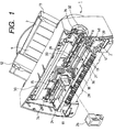
- Fig. 1 is a perspective view of a recording apparatus according to the present invention
- Fig. 2 is a sectional view of the recording apparatus according to the present invention
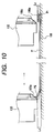
- Fig. 3 is a sectional view showing a main part of the recording apparatus according to the present invention
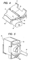
- Fig. 4 is a perspective view of a floating preventing member
- Fig. 5 is a perspective view of a jam preventing rib provided on a carriage on which a recording head is mounted
- Fig. 1 is a perspective view of a recording apparatus according to the present invention
- Fig. 2 is a sectional view of the recording apparatus according to the present invention
- Fig. 3 is a sectional view showing a main part of the recording apparatus according to the present invention
- Fig. 4 is a perspective view of a floating preventing member
- Fig. 5 is a perspective view of a jam preventing rib provided on a carriage on which a recording head is mounted
- Fig. 1 is a perspective view of a recording apparatus according to the present
- Fig. 6 is an explanatory view for explaining functions of the floating preventing member and the jam preventing rib acting on a sheet
- Fig. 7 is a block diagram of a control system of the recording apparatus according to the present invention
- Fig. 8 is a flow chart for the control system.
- a recording apparatus having an automatic sheet supplying apparatus 2 for automatically supplying sheets P made of paper, resin or the like includes a sheet supply portion 3, a sheet convey portion 4, a sheet discharge portion 5, a carriage portion 6, a cleaning portion 7 and an electric substrate 8.
- the sheet supply portion 3 includes a pressure plate 9 on which the sheets P set in the automatic sheet supplying apparatus 2 are rested, and a sheet supply roller 10 adapted to supply the sheets P rested on the pressure plate 9 and attached to a base 11.
- the pressure plate 9 is provided with a movable side guide 12 shiftable in a width-wise direction of the sheet to regulate a rested (stacked) position of the sheets P.
- the pressure plate 9 can be rotated around a rotary shaft 13 provided on the base 11 and is biased toward the sheet supply roller 10 by a pressure plate spring 14.
- a separation pad 15 formed from material having great coefficient of friction such as synthetic leather and adapted to prevent double-feed of the sheets P is provided on a portion of the pressure plate opposed to the sheet supply roller 10.
- the base 11 is provided with a separation pawl (not shown) for covering one corner of the sheet stack P and for separating the sheets P one by one, a bank portion 16 integrally formed with the base 11, and a release cam 17 for releasing engagement between the pressure plate and the sheet supply roller 10.
- the pressure plate 9 in a waiting condition, the pressure plate 9 is lowered to a predetermined position by the pressure plate 9, so that the pressure plate 9 is disengaged from the sheet supply roller 10.
- a rotational driving force transmitted to a convey roller 18 constituting a first sheet convey means (described later) is transmitted to the sheet supply roller 10 and the release cam 17 through a gear train, the release cam 17 is separated from the pressure plate 9, with the result that the sheet stack P on the pressure plate is urged against the sheet supply roller 10.
- the sheet supply roller 10 is rotated, the supplying of the sheets P is started.
- the sheets P are separated one by one by the separation pawl (not shown) and the separated sheet is sent to the sheet supply portion 3.
- the sheet supply roller 10 and the release cam 17 are rotated until the sheet P is sent to the sheet supply portion 3, and, thereafter the waiting condition that the sheet stack P is disengaged from the sheet supply roller 10 is restored, and the rotational driving force transmitted from the convey roller 18 is not transmitted to the sheet supply roller and the release cam.
- the sheet convey portion 4 includes the convey roller (first sheet convey means) and a pinch roller 19 urged against the convey roller 18 and cooperating with the convey roller to pinch and convey the sheet P fed by the sheet supply roller 10, and a sensor lever 20 (Fig. 3) constituting a tail end detection means is disposed at a downstream side of the sheet supply roller 10 and an upstream side of the convey roller 10.
- the pinch roller 19 is rotatably held by a pinch roller guide 21 and is biased by a pinch roller spring 22 so that the pinch roller 18 is urged against the convey roller 18 to form a nip n (therebetween) for conveying and supporting the sheet while pinching the sheet.
- An upper guide 23 and a platen 24 for guiding the sheet P is disposed at an entrance of the sheet convey portion 4, and the sensor lever 20 for transmitting the detection of tip and tail ends of the sheet P to a tail end detection sensor 25 is provided on the upper guide 23.
- the sensor lever 20 is rotatably supported On a shaft 20a and is biased by a biasing spring (not shown) so that, when the sheet P is not passed through the sensor lever, a flag 20b of the sensor lever 20 is lowered below a sheet conveying plane toward the platen 24. In this case, a sensor operation portion 20c of the sensor lever 20 blocks a light path of the tail end detection sensor 25, thereby turning the tail end detection sensor 25 OFF.
- the tail end detection sensor 25 is switched from OFF to ON, and, after the tail end of the sheet P is passed through the sensor lever 20, the tail end detection sensor 25 is switched from ON to OFF.
- the passing timings of the tip end and the tail end of the sheet P can be detected by the tail end detection sensor 25, and, on the basis of the detected information, positions of the tip end and the tail end of the sheet P conveyed through the sheet convey portion 4 can be recognized.
- the sheet P sent by the sheet supply portion 3 is guided by the platen 24, upper guide 23 and pinch roller guide 21 to be introduced into the nip n between the convey roller 18 and the pinch roller 19.
- the tip end of the conveyed sheet P is detected by the sensor lever 20, thereby setting a recording position of the sheet P.
- the sheet P is conveyed while being pinched and supported by the nip n between the convey roller 18 rotated by an LF (line feed) motor (not shown) and the pinch roller 19 rotatingly driven by rotation of the convey roller 18.
- the carriage portion 6 includes a carriage 28 disposed at a downstream side of the convey roller 18 and shiftable in a direction (main scanning-direction) perpendicular to a sheet conveying direction, and an ink jet recording head (recording means for recording an image in response to image information) 26 is mounted on the carriage 28.
- the carriage 28 is supported by a guide shaft 29 for reciprocally scanning the carriage in the direction (main scanning direction) perpendicular to the sheet conveying direction and a guide rail 30 for holding a tail end of the carriage 28 to maintain a gap between the recording head and the sheet P, and the guide shaft 29 and the guide rail 30 are attached to a chassis 31 of the image forming apparatus.
- the carriage 28 is driven by a carriage motor 32 attached to the chassis 31 through a timing belt 33.
- the timing belt 33 is subjected to tension from an idle pulley 34.
- the carriage 28 is provided with a flexible substrate 35 for transmitting a record signal from an electric substrate 8 to the recording head 26.
- the sheet P is conveyed, by the pair of rollers (convey roller 18 and the pinch roller 19), to a line position (position in the sheet conveying direction) where the image is recorded, and the carriage 28 is shifted, by the carriage motor 32, to a row position (position in the direction perpendicular to the sheet conveying direction) where the image is recorded, thereby positioning the recording head 26 at the image recording position: Thereafter, in response to the record signal from the electric substrate 8, the reCording head 26 discharges ink toward the sheet P, thereby recording the image on the sheet.
- the recording head 26 has fine liquid discharge openings (orifices), liquid passages, energy acting portions provided in the respective liquid passages, and energy generating means for generating liquid droplet forming energy acting on liquids in the acting portions.
- recording methods utilizing such energy generating means for generating energy there are a recording method using electrical/mechanical converters such as piezo-electric elements, a recording method using energy generating means in which heat is generated by illumination of electromagnetic wave such as laser and liquid droplet is discharged by the action of the heat, and a recording method using energy generating means in which liquid is heated by electrical/thermal converters such as heat generating elements having heat generating resistance bodies to discharge the liquid.
- a recording head used in an ink jet recording method for discharging liquid by thermal energy can record an image with high resolving power since liquid discharge openings (orifices) for forming and discharging recording liquid droplets can be arranged with high density.
- recording heads using the electrical/thermal converters as the energy generating means can easily be made compact, can fully utilize merits of IC techniques and micro-working techniques in which progress of technique and improvement of reliability have been remarkable in a recent semi-conductor field, can be mounted with high density and can be manufactured cheaply.
- the recording means may be designed so that an electrical/thermal converter is energized in response to a record signal and ink is discharged from a discharge opening by growth and contraction of a bubble generated in the ink by film boiling caused in the ink by thermal energy generated by the electrical/thermal converter.
- the sheet discharge portion 5 includes a discharge roller (second sheet convey means) 36 disposed at a downstream side of the recording head 26, and a rotatable spurred roller 37 urged against the discharge roller 36, and a transmission roller 38 is urged against the discharge roller 36 and is also urged against the convey roller 18. Accordingly, the rotational driving force of the convey roller 18 is transmitted to the discharge roller 36 via the transmission roller 38, and the spurred roller 37 is rotatingly driven by rotation of the discharge roller 36.
- a discharge roller (second sheet convey means) 36 disposed at a downstream side of the recording head 26, and a rotatable spurred roller 37 urged against the discharge roller 36, and a transmission roller 38 is urged against the discharge roller 36 and is also urged against the convey roller 18. Accordingly, the rotational driving force of the convey roller 18 is transmitted to the discharge roller 36 via the transmission roller 38, and the spurred roller 37 is rotatingly driven by rotation of the discharge roller 36.
- the sheet P on which the image was formed in the carriage portion 6 is conveyed by the discharge roller 36 and the spurred roller 37 while being pinched and supported by a nip between the discharge roller and the spurred roller, and then is discharged onto a discharge tray (not shown) disposed out of the apparatus.
- the cleaning portion 7 includes a pump 39 for cleaning the recording head 26, a cap 40 for suppressing the drying of the recording head 26, and a drive switching arm 41 for switching the driving force from the discharge roller 36 between the sheet supply portion 3 and the pump 39.
- a floating preventing portion (floating preventing member or floating regulating member) 24a for holding-down an upper surface of the sheet at one lateral edge Pr (convey reference side) thereof along the sheet conveying direction to prevent the lateral edge Pr from floating is integrally formed with the platen 24, and, as shown in Figs. 5 and 6, a jam preventing rib 28a for guiding an opposite lateral edge Pl of the sheet P by abutting against the lateral edge Pl is formed on a lower surface of the carriage 28 on which the recording head 26 is mounted.
- the electric block diagram shown in Fig. 7 includes a printer controller 42 for carrying out electrical/mechanical control at a high speed with hardware, a RAM (random access memory) 43, a ROM (read only memory) 44, and a CPU (central processing unit) 45 for effecting total control.
- a printer controller 42 for carrying out electrical/mechanical control at a high speed with hardware
- a RAM random access memory
- ROM read only memory
- CPU central processing unit
- the printer controller 42 is a GA having several thousands of gates and includes therein an interface control part 48 for communicating with an external host 46 to receive the image data and for successively accumulating the data in a receiving buffer 47 of the RAM 43, a mechanism control part 59 for controlling the LF motor 27, carriage motor 32, key switch and LED (light emitting diode) 49, and a recording head control part 50 for reforming the image data to a recordable form and accumulating it in a printing buffer 51 and for sending the data to the recording head at a proper timing to effect the recording.
- an interface control part 48 for communicating with an external host 46 to receive the image data and for successively accumulating the data in a receiving buffer 47 of the RAM 43
- a mechanism control part 59 for controlling the LF motor 27, carriage motor 32, key switch and LED (light emitting diode) 49
- a recording head control part 50 for reforming the image data to a recordable form and accumulating it in a printing buffer 51 and for sending the data to the recording head at a proper timing to
- the RAM 43 is divided into the receiving buffer 47 and the printing buffer 51.
- the printing buffer 51 has a function for storing the data divided so that the recording head 26 becomes a recordable condition just at one scanning.
- ROM 44 has a programming part 53 for storing program code controlling the CPU 45, and a CG (character generator) 54 for storing character font data.
- the CPU 45 controls the printer controller 42, RAM 43 and ROM 44 in accordance with the program code and always monitors the condition of the tail end detection sensor 25.
- a waiting condition is established.
- the image forming apparatus 1 effects the predetermined operation.
- the data received through the interface control part 48 is subjected to data conversion process (treatment) by the CPU 45 while being spooled in the receiving buffer 47 timely, and thereafter, the data is divided into amounts recordable by one scanning of the recording head 26 and is sent to the printing buffer 51.
- the data in the printing buffer 51 is timely sent to the recording head 26 through the flexible substrate 35 under the control of the printer controller 42 and the CPU 45.
- the CPU 45 drives the carriage motor 32 timely so that the desired image can be recorded at a desired position.
- the CPU 45 drives the LF motor 27 by a predetermined amount, thereby conveying the sheet P.
- the CPU 45 monitors the tail end detection sensor 25 during the conveyance of the sheet so that the CPU controls the passing timing of the tip and tail ends of the sheet P by turning ON/OFF the tail end detection sensor 25 by operating the sensor lever 20 by the tip and tail ends of the sheet P.
- the tail end Pb of the sheet P is detected by turning the tail end detection sensor 25 OFF by blocking the light path of the tail end detection sensor 25 by the sensor operation portion 20c of the sensor lever 20 rotated around the shaft 20a in the clockwise direction (Fig. 3) by the biasing spring (not shown) when the tail end Pb reaches a position M 0 in Fig. 3 to be separated from the sensor lever 20.
- this timing is stored in the CPU 45, by adding the further convey count of the sheet P to the stored data timely, the position of the tail end Pb of the sheet P can be recognized.
- the sheet P Before the tail end Pb of the sheet P is detected, since the sheet P is pinched and supported by the nip n between the convey roller 18 and the pinch roller 19, the sheet P is not floating. Thus, before the tail end Pb of the sheet P is detected, the normal recording conveyance control may be effected.
- step S1 in Fig. 8 if the tail end Pb of the sheet P is not detected by the tail end detection sensor 25, immediately after the one scanning recording stored in the printing buffer 51 is effected by the recording head 26 (step S2), the predetermined amount of sheet conveyance is effected (step S3), and, at the same time, the carriage 28 is returned to return the recording head 26 to the record start position (home position) (step S4).
- the conveyance control may be effected as described regarding the steps S2 to S4; however, if the tail end Pb of the sheet P passed through the nip n between the convey roller 18 and the pinch roller 19 is released from the nip n, the sheet is not supported, with the result that, when the carriage 28 being returned passes through the other lateral edge Pl of the sheet P which is not held-down by the floating preventing portion 24a, the carriage may abut against the other lateral edge Pl to cause the sheet jam or poor operation of the carriage.
- step S5 even if the tail end Pb of the sheet P is positioned in the upstream side of the nip n between the convey roller 18 and the pinch roller 19, depending on judgement at step S6, control which is similar to the control effected if the tail end Pb of the sheet P is positioned in the downstream side of the nip n between the convey roller 18 and the pinch roller 19 in the step S5 is effected. That is, if it is recognized at the step S6 that, during the sheet conveyance after the next one scanning, the tail end Pb of the sheet P is shifted in the downstream side of the nip n between the convey roller 18 and the pinch roller 19 not to be supported.
- the control effected if the tail end Pb of the sheet P is positioned in the downstream side of the nip n between the convey roller 18 and the pinch roller 19 is divided into two in accordance with the number of succeeding recording scanning times.
- next scanning it is judged whether or not the data to be recorded on the sheet P is finished in a step S7; and, if it is judged that the data to be recorded on the sheet P is finished in the next scanning (i.e., if the next one scanning is the last scanning), after the recording for one scanning stored in the buffer 51 is effected by the recording head 26 (step S8), the carriage 28 does not carry out the returning operation but is shifted out of the other lateral edge Pl of the sheet P opposite to the record start position (step S9). In a condition that the carriage 28 is stopped at this area out of the sheet passing area, the sheet P is discharged (step S10).
- step S11 After the sheet P is discharged and the tail end Pb of the sheet P is sufficiently spaced apart from the carriage 28, at least when the tail end Pb of the sheet P is discharged up to the downstream side of a position M 1 shown in Fig. 3, the carriage 28 is returned to prepare for the next recording to the sheet P (step S11).
- step S7 if the data to be recorded on the sheet P is not finished in the next scanning, after the recording for one scanning stored in the buffer 51 is effected by the recording head 26 (step S12), the conveyance of the sheet P is not effected, but, the carriage 28 is immediately returned to the record start position (step S13). And, the sheet is conveyed by a predetermined amount in a condition that the carriage 28 is stopped at the record start position (step S14).
- step S14 in the conveyance of the sheet P effected in the condition that the carriage 28 is stopped at the record start position, since the floating preventing portion 24a is positioned in the vicinity of the carriage 20, the carriage 28 (or the recording head 26) does not contact with the sheet P.
- Step S6 if it is recognized that the tail end Pb of the sheet P is positioned in the upstream side of the nip n between the convey roller 18 and the pinch roller 19 in the sheet conveyance after the next one scanning, the control similar to the steps S2 to S4 is effected (steps S15 to S17).
- the recording area can be increased by an effective recording width of the recording head 26 at the maximum by using the similar construction as the above-mentioned embodiment.
- the recording apparatus may be applied to a copying apparatus in combination with a reader or a facsimile having a transmission function, as well as an image outputting terminal device of an information processing equipment such as a computer.
- the recording system of the present invention is not limited to the ink jet recording system, but, for example, a heat transfer recording system, a photosensitive recording system, an impact recording system such as a wire dot recording system or other recording systems can be used.
- the recording apparatus and the method for controlling such a recording apparatus has the above-mentioned construction and function, regardless of material, curvature curl and thickness of the sheet, in the recording operation at the tail end portion of the sheet, the sheet jam and the poor operation of the recording means can be prevented, and the recording range at the tail end portion of the sheet can be increased, and the recording apparatus having high reliability can be provided.
- the recording area can be increased by the effective recording width of the recording head 26 at the maximum.
- the recording head When the last line recording is effected by a recording head at a tail end portion of a sheet, the recording head is controlled not to be passed through a lateral edge of the sheet opposite to or remote from a floating preventing portion, whereby a recording apparatus and a method for controlling such a recording apparatus in which a recording range at the tail end portion of the sheet can be increased without interfering with a scanning operation of the recording means regardless of kinds of sheets.
Landscapes
- Engineering & Computer Science (AREA)
- Multimedia (AREA)
- Signal Processing (AREA)
- Ink Jet (AREA)
- Handling Of Sheets (AREA)
Applications Claiming Priority (3)
| Application Number | Priority Date | Filing Date | Title |
|---|---|---|---|
| JP4593497 | 1997-02-28 | ||
| JP45934/97 | 1997-02-28 | ||
| JP4593497 | 1997-02-28 |
Publications (3)
| Publication Number | Publication Date |
|---|---|
| EP0862314A2 true EP0862314A2 (de) | 1998-09-02 |
| EP0862314A3 EP0862314A3 (de) | 1998-10-21 |
| EP0862314B1 EP0862314B1 (de) | 2004-09-22 |
Family
ID=12733106
Family Applications (1)
| Application Number | Title | Priority Date | Filing Date |
|---|---|---|---|
| EP98103475A Expired - Lifetime EP0862314B1 (de) | 1997-02-28 | 1998-02-27 | Aufzeichnungsgerät und Verfahren zur Steuerung eines solchen Aufzeichnungsgeräts |
Country Status (3)
| Country | Link |
|---|---|
| US (1) | US6231159B1 (de) |
| EP (1) | EP0862314B1 (de) |
| DE (1) | DE69826348T2 (de) |
Cited By (1)
| Publication number | Priority date | Publication date | Assignee | Title |
|---|---|---|---|---|
| EP1291190A3 (de) * | 2001-09-07 | 2003-11-05 | Canon Kabushiki Kaisha | Aufzeichnungsgerät und Element zur Verhinderung des Schwebens von Aufzeichnungsmaterial |
Families Citing this family (3)
| Publication number | Priority date | Publication date | Assignee | Title |
|---|---|---|---|---|
| JP4890693B2 (ja) * | 2001-08-10 | 2012-03-07 | キヤノン株式会社 | インクジェット記録装置 |
| JP4777187B2 (ja) * | 2006-08-23 | 2011-09-21 | キヤノン株式会社 | 記録装置及び記録方法 |
| JP6393966B2 (ja) * | 2013-08-30 | 2018-09-26 | セイコーエプソン株式会社 | プリンター |
Family Cites Families (11)
| Publication number | Priority date | Publication date | Assignee | Title |
|---|---|---|---|---|
| US4138102A (en) | 1977-03-30 | 1979-02-06 | Xerox Corporation | Automatic document processing device |
| JPS6410772A (en) * | 1987-07-02 | 1989-01-13 | Tokyo Electric Co Ltd | Original reader |
| US4953037A (en) | 1988-02-05 | 1990-08-28 | Canon Kabushiki Kaisha | Original reading apparatus |
| JPH02226178A (ja) * | 1989-02-27 | 1990-09-07 | Ricoh Co Ltd | 熱ローラー定着装置のペーパーガイド装置 |
| JPH0373940A (ja) * | 1989-08-16 | 1991-03-28 | Ricoh Co Ltd | 原稿搬送装置 |
| JPH07120094B2 (ja) | 1989-09-26 | 1995-12-20 | 富士ゼロックス株式会社 | 原稿読み取り方法、原稿読み取り装置及び複写方法 |
| US5602571A (en) * | 1990-03-14 | 1997-02-11 | Canon Kabushiki Kaisha | Sheet feeding apparatus and recording system with it |
| DE69119474T2 (de) * | 1990-06-01 | 1996-10-24 | Canon Kk | Schreibgerät mit einer elektronischen Schreibmaschine |
| US5480247A (en) | 1992-05-29 | 1996-01-02 | Canon Kabushiki Kaisha | Sheet supplying apparatus |
| JPH071781A (ja) * | 1993-06-17 | 1995-01-06 | Brother Ind Ltd | プリンタ |
| JP3495804B2 (ja) | 1994-01-25 | 2004-02-09 | キヤノン株式会社 | 記録媒体搬送機構および該機構を用いたインクジェット記録装置 |
-
1998
- 1998-02-27 DE DE69826348T patent/DE69826348T2/de not_active Expired - Lifetime
- 1998-02-27 US US09/031,795 patent/US6231159B1/en not_active Expired - Fee Related
- 1998-02-27 EP EP98103475A patent/EP0862314B1/de not_active Expired - Lifetime
Cited By (2)
| Publication number | Priority date | Publication date | Assignee | Title |
|---|---|---|---|---|
| EP1291190A3 (de) * | 2001-09-07 | 2003-11-05 | Canon Kabushiki Kaisha | Aufzeichnungsgerät und Element zur Verhinderung des Schwebens von Aufzeichnungsmaterial |
| US6869176B2 (en) | 2001-09-07 | 2005-03-22 | Canon Kabushiki Kaisha | Recording apparatus, and recording medium floating prevention member |
Also Published As
| Publication number | Publication date |
|---|---|
| DE69826348D1 (de) | 2004-10-28 |
| EP0862314B1 (de) | 2004-09-22 |
| EP0862314A3 (de) | 1998-10-21 |
| US6231159B1 (en) | 2001-05-15 |
| DE69826348T2 (de) | 2005-11-10 |
Similar Documents
| Publication | Publication Date | Title |
|---|---|---|
| EP0658433B1 (de) | Vorrichtung zum Papiervorschub und zur Schräglaufkorrektur | |
| US5725208A (en) | Sheet supplying and conveying apparatus | |
| JP4551719B2 (ja) | インクジェット記録装置およびインクジェット記録装置の制御方法 | |
| US6131899A (en) | Sheet supplying apparatus | |
| CN1188046A (zh) | 喷墨打印机的出纸装置 | |
| US7021757B2 (en) | Both-side recording apparatus | |
| US7134658B2 (en) | Recording apparatus having skew removal | |
| EP0862314B1 (de) | Aufzeichnungsgerät und Verfahren zur Steuerung eines solchen Aufzeichnungsgeräts | |
| US6382857B1 (en) | Bearing mechanism and conveying apparatus and recording apparatus | |
| JP3762344B2 (ja) | 記録装置 | |
| US6341905B1 (en) | Recording apparatus | |
| US6517200B1 (en) | Transport buffer having force limiting drive means and method | |
| JPH09104559A (ja) | 記録装置 | |
| JP3667078B2 (ja) | 記録装置 | |
| US6886900B2 (en) | Inkjet image forming apparatus and inkjet image forming method | |
| US6851801B2 (en) | Recording material conveying device and ink jet recording apparatus using such device | |
| JPH09109508A (ja) | 記録装置 | |
| JP3747875B2 (ja) | インクジェット記録装置 | |
| JP3995442B2 (ja) | 記録装置 | |
| JP2008110530A (ja) | 搬送装置及び画像形成装置 | |
| JPH08198492A (ja) | シート搬送装置および記録装置 | |
| JP2000344408A (ja) | 記録装置 | |
| JPH0299365A (ja) | 記録装置 | |
| JPH07108727A (ja) | インクジェット記録装置 | |
| JPH07125358A (ja) | インクジェット記録装置 |
Legal Events
| Date | Code | Title | Description |
|---|---|---|---|
| PUAI | Public reference made under article 153(3) epc to a published international application that has entered the european phase |
Free format text: ORIGINAL CODE: 0009012 |
|
| AK | Designated contracting states |
Kind code of ref document: A2 Designated state(s): DE ES FR GB IT NL |
|
| AX | Request for extension of the european patent |
Free format text: AL;LT;LV;MK;RO;SI |
|
| PUAL | Search report despatched |
Free format text: ORIGINAL CODE: 0009013 |
|
| AK | Designated contracting states |
Kind code of ref document: A3 Designated state(s): AT BE CH DE DK ES FI FR GB GR IE IT LI LU MC NL PT SE |
|
| AX | Request for extension of the european patent |
Free format text: AL;LT;LV;MK;RO;SI |
|
| 17P | Request for examination filed |
Effective date: 19990303 |
|
| AKX | Designation fees paid |
Free format text: DE ES FR GB IT NL |
|
| 17Q | First examination report despatched |
Effective date: 20030415 |
|
| GRAP | Despatch of communication of intention to grant a patent |
Free format text: ORIGINAL CODE: EPIDOSNIGR1 |
|
| GRAS | Grant fee paid |
Free format text: ORIGINAL CODE: EPIDOSNIGR3 |
|
| GRAA | (expected) grant |
Free format text: ORIGINAL CODE: 0009210 |
|
| AK | Designated contracting states |
Kind code of ref document: B1 Designated state(s): DE ES FR GB IT NL |
|
| PG25 | Lapsed in a contracting state [announced via postgrant information from national office to epo] |
Ref country code: NL Free format text: LAPSE BECAUSE OF FAILURE TO SUBMIT A TRANSLATION OF THE DESCRIPTION OR TO PAY THE FEE WITHIN THE PRESCRIBED TIME-LIMIT Effective date: 20040922 |
|
| REG | Reference to a national code |
Ref country code: GB Ref legal event code: FG4D |
|
| REF | Corresponds to: |
Ref document number: 69826348 Country of ref document: DE Date of ref document: 20041028 Kind code of ref document: P |
|
| PG25 | Lapsed in a contracting state [announced via postgrant information from national office to epo] |
Ref country code: ES Free format text: LAPSE BECAUSE OF FAILURE TO SUBMIT A TRANSLATION OF THE DESCRIPTION OR TO PAY THE FEE WITHIN THE PRESCRIBED TIME-LIMIT Effective date: 20050102 |
|
| NLV1 | Nl: lapsed or annulled due to failure to fulfill the requirements of art. 29p and 29m of the patents act | ||
| PLBE | No opposition filed within time limit |
Free format text: ORIGINAL CODE: 0009261 |
|
| STAA | Information on the status of an ep patent application or granted ep patent |
Free format text: STATUS: NO OPPOSITION FILED WITHIN TIME LIMIT |
|
| ET | Fr: translation filed | ||
| 26N | No opposition filed |
Effective date: 20050623 |
|
| PGFP | Annual fee paid to national office [announced via postgrant information from national office to epo] |
Ref country code: IT Payment date: 20090205 Year of fee payment: 12 |
|
| PGFP | Annual fee paid to national office [announced via postgrant information from national office to epo] |
Ref country code: FR Payment date: 20090223 Year of fee payment: 12 |
|
| REG | Reference to a national code |
Ref country code: FR Ref legal event code: ST Effective date: 20101029 |
|
| PG25 | Lapsed in a contracting state [announced via postgrant information from national office to epo] |
Ref country code: FR Free format text: LAPSE BECAUSE OF NON-PAYMENT OF DUE FEES Effective date: 20100301 |
|
| PG25 | Lapsed in a contracting state [announced via postgrant information from national office to epo] |
Ref country code: IT Free format text: LAPSE BECAUSE OF NON-PAYMENT OF DUE FEES Effective date: 20100227 |
|
| PGFP | Annual fee paid to national office [announced via postgrant information from national office to epo] |
Ref country code: DE Payment date: 20120229 Year of fee payment: 15 |
|
| PGFP | Annual fee paid to national office [announced via postgrant information from national office to epo] |
Ref country code: GB Payment date: 20120224 Year of fee payment: 15 |
|
| GBPC | Gb: european patent ceased through non-payment of renewal fee |
Effective date: 20130227 |
|
| REG | Reference to a national code |
Ref country code: DE Ref legal event code: R119 Ref document number: 69826348 Country of ref document: DE Effective date: 20130903 |
|
| PG25 | Lapsed in a contracting state [announced via postgrant information from national office to epo] |
Ref country code: DE Free format text: LAPSE BECAUSE OF NON-PAYMENT OF DUE FEES Effective date: 20130903 Ref country code: GB Free format text: LAPSE BECAUSE OF NON-PAYMENT OF DUE FEES Effective date: 20130227 |