EP0863128A1 - Fluorierte polyfunktionelle (meth)acrylester,zusammensetzungen,materialien mit niedriger brechung und antireflektionsfilmen - Google Patents
Fluorierte polyfunktionelle (meth)acrylester,zusammensetzungen,materialien mit niedriger brechung und antireflektionsfilmen Download PDFInfo
- Publication number
- EP0863128A1 EP0863128A1 EP97924352A EP97924352A EP0863128A1 EP 0863128 A1 EP0863128 A1 EP 0863128A1 EP 97924352 A EP97924352 A EP 97924352A EP 97924352 A EP97924352 A EP 97924352A EP 0863128 A1 EP0863128 A1 EP 0863128A1
- Authority
- EP
- European Patent Office
- Prior art keywords
- meth
- acrylate
- fluorine
- group
- reaction
- Prior art date
- Legal status (The legal status is an assumption and is not a legal conclusion. Google has not performed a legal analysis and makes no representation as to the accuracy of the status listed.)
- Granted
Links
- 239000000203 mixture Substances 0.000 title claims abstract description 127
- 239000000463 material Substances 0.000 title claims abstract description 91
- 150000001252 acrylic acid derivatives Chemical class 0.000 title description 2
- NIXOWILDQLNWCW-UHFFFAOYSA-M Acrylate Chemical compound [O-]C(=O)C=C NIXOWILDQLNWCW-UHFFFAOYSA-M 0.000 claims abstract description 109
- 229910052731 fluorine Inorganic materials 0.000 claims abstract description 61
- YCKRFDGAMUMZLT-UHFFFAOYSA-N Fluorine atom Chemical compound [F] YCKRFDGAMUMZLT-UHFFFAOYSA-N 0.000 claims abstract description 60
- 239000011737 fluorine Substances 0.000 claims abstract description 60
- 230000001603 reducing effect Effects 0.000 claims abstract description 42
- -1 methacryloyl group Chemical group 0.000 claims abstract description 34
- 125000003647 acryloyl group Chemical group O=C([*])C([H])=C([H])[H] 0.000 claims abstract description 19
- 125000003709 fluoroalkyl group Chemical group 0.000 claims abstract description 4
- 125000000217 alkyl group Chemical group 0.000 claims abstract description 3
- 125000005348 fluorocycloalkyl group Chemical group 0.000 claims abstract description 3
- 238000000576 coating method Methods 0.000 claims description 78
- 239000011248 coating agent Substances 0.000 claims description 72
- 238000005299 abrasion Methods 0.000 claims description 26
- 238000006116 polymerization reaction Methods 0.000 claims description 25
- 239000000758 substrate Substances 0.000 claims description 21
- 238000000034 method Methods 0.000 claims description 14
- 239000000843 powder Substances 0.000 claims description 13
- 230000001588 bifunctional effect Effects 0.000 claims description 8
- 125000004435 hydrogen atom Chemical group [H]* 0.000 claims description 8
- 150000002484 inorganic compounds Chemical class 0.000 claims description 8
- 229910010272 inorganic material Inorganic materials 0.000 claims description 8
- 125000004432 carbon atom Chemical group C* 0.000 claims description 7
- 125000002887 hydroxy group Chemical group [H]O* 0.000 claims description 7
- 125000001153 fluoro group Chemical group F* 0.000 claims description 6
- HEDRZPFGACZZDS-MICDWDOJSA-N Trichloro(2H)methane Chemical compound [2H]C(Cl)(Cl)Cl HEDRZPFGACZZDS-MICDWDOJSA-N 0.000 description 64
- 238000006243 chemical reaction Methods 0.000 description 56
- 239000007788 liquid Substances 0.000 description 56
- 150000005690 diesters Chemical class 0.000 description 48
- 230000003595 spectral effect Effects 0.000 description 36
- HEDRZPFGACZZDS-UHFFFAOYSA-N Chloroform Chemical compound ClC(Cl)Cl HEDRZPFGACZZDS-UHFFFAOYSA-N 0.000 description 34
- 239000002904 solvent Substances 0.000 description 34
- 150000001875 compounds Chemical class 0.000 description 32
- XEKOWRVHYACXOJ-UHFFFAOYSA-N Ethyl acetate Chemical compound CCOC(C)=O XEKOWRVHYACXOJ-UHFFFAOYSA-N 0.000 description 27
- 150000005691 triesters Chemical class 0.000 description 27
- 238000005259 measurement Methods 0.000 description 26
- 239000000047 product Substances 0.000 description 25
- ZMANZCXQSJIPKH-UHFFFAOYSA-N Triethylamine Chemical compound CCN(CC)CC ZMANZCXQSJIPKH-UHFFFAOYSA-N 0.000 description 24
- 239000012295 chemical reaction liquid Substances 0.000 description 24
- 238000004293 19F NMR spectroscopy Methods 0.000 description 22
- 238000005160 1H NMR spectroscopy Methods 0.000 description 22
- XBDQKXXYIPTUBI-UHFFFAOYSA-M Propionate Chemical compound CCC([O-])=O XBDQKXXYIPTUBI-UHFFFAOYSA-M 0.000 description 20
- HFBMWMNUJJDEQZ-UHFFFAOYSA-N acryloyl chloride Chemical compound ClC(=O)C=C HFBMWMNUJJDEQZ-UHFFFAOYSA-N 0.000 description 20
- 150000002148 esters Chemical class 0.000 description 20
- 150000001732 carboxylic acid derivatives Chemical class 0.000 description 19
- KFZMGEQAYNKOFK-UHFFFAOYSA-N Isopropanol Chemical compound CC(C)O KFZMGEQAYNKOFK-UHFFFAOYSA-N 0.000 description 18
- 238000010894 electron beam technology Methods 0.000 description 18
- 238000002360 preparation method Methods 0.000 description 18
- XLYOFNOQVPJJNP-UHFFFAOYSA-N water Substances O XLYOFNOQVPJJNP-UHFFFAOYSA-N 0.000 description 18
- GETTZEONDQJALK-UHFFFAOYSA-N (trifluoromethyl)benzene Chemical compound FC(F)(F)C1=CC=CC=C1 GETTZEONDQJALK-UHFFFAOYSA-N 0.000 description 17
- 239000013078 crystal Substances 0.000 description 17
- CYRMSUTZVYGINF-UHFFFAOYSA-N trichlorofluoromethane Chemical compound FC(Cl)(Cl)Cl CYRMSUTZVYGINF-UHFFFAOYSA-N 0.000 description 16
- YMWUJEATGCHHMB-UHFFFAOYSA-N Dichloromethane Chemical compound ClCCl YMWUJEATGCHHMB-UHFFFAOYSA-N 0.000 description 15
- 239000000178 monomer Substances 0.000 description 15
- 238000002156 mixing Methods 0.000 description 14
- 230000000052 comparative effect Effects 0.000 description 13
- 238000001816 cooling Methods 0.000 description 13
- 238000011156 evaluation Methods 0.000 description 13
- YXFVVABEGXRONW-UHFFFAOYSA-N Toluene Chemical compound CC1=CC=CC=C1 YXFVVABEGXRONW-UHFFFAOYSA-N 0.000 description 12
- 239000003112 inhibitor Substances 0.000 description 11
- 229920000139 polyethylene terephthalate Polymers 0.000 description 11
- 239000005020 polyethylene terephthalate Substances 0.000 description 11
- QIGBRXMKCJKVMJ-UHFFFAOYSA-N Hydroquinone Chemical compound OC1=CC=C(O)C=C1 QIGBRXMKCJKVMJ-UHFFFAOYSA-N 0.000 description 10
- 239000003054 catalyst Substances 0.000 description 10
- 125000001495 ethyl group Chemical group [H]C([H])([H])C([H])([H])* 0.000 description 10
- VLKZOEOYAKHREP-UHFFFAOYSA-N n-Hexane Chemical compound CCCCCC VLKZOEOYAKHREP-UHFFFAOYSA-N 0.000 description 10
- 239000000243 solution Substances 0.000 description 10
- 229920002799 BoPET Polymers 0.000 description 9
- VEXZGXHMUGYJMC-UHFFFAOYSA-N Hydrochloric acid Chemical compound Cl VEXZGXHMUGYJMC-UHFFFAOYSA-N 0.000 description 9
- OKKJLVBELUTLKV-UHFFFAOYSA-N Methanol Chemical compound OC OKKJLVBELUTLKV-UHFFFAOYSA-N 0.000 description 9
- 238000004440 column chromatography Methods 0.000 description 9
- 238000005292 vacuum distillation Methods 0.000 description 9
- VZSRBBMJRBPUNF-UHFFFAOYSA-N 2-(2,3-dihydro-1H-inden-2-ylamino)-N-[3-oxo-3-(2,4,6,7-tetrahydrotriazolo[4,5-c]pyridin-5-yl)propyl]pyrimidine-5-carboxamide Chemical compound C1C(CC2=CC=CC=C12)NC1=NC=C(C=N1)C(=O)NCCC(N1CC2=C(CC1)NN=N2)=O VZSRBBMJRBPUNF-UHFFFAOYSA-N 0.000 description 8
- 229920002284 Cellulose triacetate Polymers 0.000 description 8
- NNLVGZFZQQXQNW-ADJNRHBOSA-N [(2r,3r,4s,5r,6s)-4,5-diacetyloxy-3-[(2s,3r,4s,5r,6r)-3,4,5-triacetyloxy-6-(acetyloxymethyl)oxan-2-yl]oxy-6-[(2r,3r,4s,5r,6s)-4,5,6-triacetyloxy-2-(acetyloxymethyl)oxan-3-yl]oxyoxan-2-yl]methyl acetate Chemical compound O([C@@H]1O[C@@H]([C@H]([C@H](OC(C)=O)[C@H]1OC(C)=O)O[C@H]1[C@@H]([C@@H](OC(C)=O)[C@H](OC(C)=O)[C@@H](COC(C)=O)O1)OC(C)=O)COC(=O)C)[C@@H]1[C@@H](COC(C)=O)O[C@@H](OC(C)=O)[C@H](OC(C)=O)[C@H]1OC(C)=O NNLVGZFZQQXQNW-ADJNRHBOSA-N 0.000 description 8
- 231100000987 absorbed dose Toxicity 0.000 description 8
- 239000007789 gas Substances 0.000 description 8
- 239000003999 initiator Substances 0.000 description 8
- 238000004811 liquid chromatography Methods 0.000 description 8
- 238000000926 separation method Methods 0.000 description 8
- 150000002924 oxiranes Chemical class 0.000 description 7
- 229920000642 polymer Polymers 0.000 description 7
- HMXSIEIEXLGIET-UHFFFAOYSA-N 2-(2,2,3,3,4,4,5,5,6,6,7,7,8,8,9,9,9-heptadecafluorononyl)oxirane Chemical compound FC(F)(F)C(F)(F)C(F)(F)C(F)(F)C(F)(F)C(F)(F)C(F)(F)C(F)(F)CC1CO1 HMXSIEIEXLGIET-UHFFFAOYSA-N 0.000 description 6
- LFQSCWFLJHTTHZ-UHFFFAOYSA-N Ethanol Chemical compound CCO LFQSCWFLJHTTHZ-UHFFFAOYSA-N 0.000 description 6
- JUJWROOIHBZHMG-UHFFFAOYSA-N Pyridine Chemical compound C1=CC=NC=C1 JUJWROOIHBZHMG-UHFFFAOYSA-N 0.000 description 6
- HEMHJVSKTPXQMS-UHFFFAOYSA-M Sodium hydroxide Chemical compound [OH-].[Na+] HEMHJVSKTPXQMS-UHFFFAOYSA-M 0.000 description 6
- 229960004592 isopropanol Drugs 0.000 description 6
- 229920005989 resin Polymers 0.000 description 6
- 239000011347 resin Substances 0.000 description 6
- JIGUICYYOYEXFS-UHFFFAOYSA-N 3-tert-butylbenzene-1,2-diol Chemical compound CC(C)(C)C1=CC=CC(O)=C1O JIGUICYYOYEXFS-UHFFFAOYSA-N 0.000 description 5
- LKVFCSWBKOVHAH-UHFFFAOYSA-N 4-Ethoxyphenol Chemical compound CCOC1=CC=C(O)C=C1 LKVFCSWBKOVHAH-UHFFFAOYSA-N 0.000 description 5
- 239000007864 aqueous solution Substances 0.000 description 5
- XXBDWLFCJWSEKW-UHFFFAOYSA-N dimethylbenzylamine Chemical compound CN(C)CC1=CC=CC=C1 XXBDWLFCJWSEKW-UHFFFAOYSA-N 0.000 description 5
- 238000003618 dip coating Methods 0.000 description 5
- 230000002401 inhibitory effect Effects 0.000 description 5
- 239000012046 mixed solvent Substances 0.000 description 5
- 239000003921 oil Substances 0.000 description 5
- 238000001953 recrystallisation Methods 0.000 description 5
- HWCKGOZZJDHMNC-UHFFFAOYSA-M tetraethylammonium bromide Chemical compound [Br-].CC[N+](CC)(CC)CC HWCKGOZZJDHMNC-UHFFFAOYSA-M 0.000 description 5
- 238000011282 treatment Methods 0.000 description 5
- OZAIFHULBGXAKX-UHFFFAOYSA-N 2-(2-cyanopropan-2-yldiazenyl)-2-methylpropanenitrile Chemical compound N#CC(C)(C)N=NC(C)(C)C#N OZAIFHULBGXAKX-UHFFFAOYSA-N 0.000 description 4
- 229920001577 copolymer Polymers 0.000 description 4
- 238000001035 drying Methods 0.000 description 4
- 239000013307 optical fiber Substances 0.000 description 4
- 239000011541 reaction mixture Substances 0.000 description 4
- CDBYLPFSWZWCQE-UHFFFAOYSA-L sodium carbonate Substances [Na+].[Na+].[O-]C([O-])=O CDBYLPFSWZWCQE-UHFFFAOYSA-L 0.000 description 4
- 239000007858 starting material Substances 0.000 description 4
- PTBDIHRZYDMNKB-UHFFFAOYSA-N 2,2-Bis(hydroxymethyl)propionic acid Chemical compound OCC(C)(CO)C(O)=O PTBDIHRZYDMNKB-UHFFFAOYSA-N 0.000 description 3
- KGYUZRBIQCDOCN-UHFFFAOYSA-N 2-(2,2,3,3,4,4,5,5,6,6,7,7,7-tridecafluoroheptyl)oxirane Chemical compound FC(F)(F)C(F)(F)C(F)(F)C(F)(F)C(F)(F)C(F)(F)CC1CO1 KGYUZRBIQCDOCN-UHFFFAOYSA-N 0.000 description 3
- WMYINDVYGQKYMI-UHFFFAOYSA-N 2-[2,2-bis(hydroxymethyl)butoxymethyl]-2-ethylpropane-1,3-diol Chemical compound CCC(CO)(CO)COCC(CC)(CO)CO WMYINDVYGQKYMI-UHFFFAOYSA-N 0.000 description 3
- TXBCBTDQIULDIA-UHFFFAOYSA-N 2-[[3-hydroxy-2,2-bis(hydroxymethyl)propoxy]methyl]-2-(hydroxymethyl)propane-1,3-diol Chemical compound OCC(CO)(CO)COCC(CO)(CO)CO TXBCBTDQIULDIA-UHFFFAOYSA-N 0.000 description 3
- KWOLFJPFCHCOCG-UHFFFAOYSA-N Acetophenone Chemical compound CC(=O)C1=CC=CC=C1 KWOLFJPFCHCOCG-UHFFFAOYSA-N 0.000 description 3
- 239000002253 acid Substances 0.000 description 3
- 150000001298 alcohols Chemical class 0.000 description 3
- 150000003973 alkyl amines Chemical group 0.000 description 3
- ISAOCJYIOMOJEB-UHFFFAOYSA-N benzoin Chemical class C=1C=CC=CC=1C(O)C(=O)C1=CC=CC=C1 ISAOCJYIOMOJEB-UHFFFAOYSA-N 0.000 description 3
- 229920006037 cross link polymer Polymers 0.000 description 3
- 238000004132 cross linking Methods 0.000 description 3
- 239000006185 dispersion Substances 0.000 description 3
- 238000001914 filtration Methods 0.000 description 3
- 239000011521 glass Substances 0.000 description 3
- 238000007756 gravure coating Methods 0.000 description 3
- 230000001678 irradiating effect Effects 0.000 description 3
- 238000002955 isolation Methods 0.000 description 3
- ORUIBWPALBXDOA-UHFFFAOYSA-L magnesium fluoride Chemical compound [F-].[F-].[Mg+2] ORUIBWPALBXDOA-UHFFFAOYSA-L 0.000 description 3
- 229910001635 magnesium fluoride Inorganic materials 0.000 description 3
- 229940059574 pentaerithrityl Drugs 0.000 description 3
- WXZMFSXDPGVJKK-UHFFFAOYSA-N pentaerythritol Chemical compound OCC(CO)(CO)CO WXZMFSXDPGVJKK-UHFFFAOYSA-N 0.000 description 3
- 239000002244 precipitate Substances 0.000 description 3
- 230000001376 precipitating effect Effects 0.000 description 3
- UMJSCPRVCHMLSP-UHFFFAOYSA-N pyridine Natural products COC1=CC=CN=C1 UMJSCPRVCHMLSP-UHFFFAOYSA-N 0.000 description 3
- 238000004528 spin coating Methods 0.000 description 3
- 150000003512 tertiary amines Chemical class 0.000 description 3
- BQCIDUSAKPWEOX-UHFFFAOYSA-N 1,1-Difluoroethene Chemical compound FC(F)=C BQCIDUSAKPWEOX-UHFFFAOYSA-N 0.000 description 2
- GZBSIABKXVPBFY-UHFFFAOYSA-N 2,2-bis(hydroxymethyl)propane-1,3-diol;prop-2-enoic acid Chemical compound OC(=O)C=C.OC(=O)C=C.OC(=O)C=C.OC(=O)C=C.OCC(CO)(CO)CO GZBSIABKXVPBFY-UHFFFAOYSA-N 0.000 description 2
- BMLZXWMOVNVCAS-UHFFFAOYSA-N 2-methyl-3-prop-2-enoyloxy-2-(prop-2-enoyloxymethyl)propanoic acid Chemical compound C=CC(=O)OCC(C)(COC(=O)C=C)C(O)=O BMLZXWMOVNVCAS-UHFFFAOYSA-N 0.000 description 2
- YLZOPXRUQYQQID-UHFFFAOYSA-N 3-(2,4,6,7-tetrahydrotriazolo[4,5-c]pyridin-5-yl)-1-[4-[2-[[3-(trifluoromethoxy)phenyl]methylamino]pyrimidin-5-yl]piperazin-1-yl]propan-1-one Chemical compound N1N=NC=2CN(CCC=21)CCC(=O)N1CCN(CC1)C=1C=NC(=NC=1)NCC1=CC(=CC=C1)OC(F)(F)F YLZOPXRUQYQQID-UHFFFAOYSA-N 0.000 description 2
- VVBLNCFGVYUYGU-UHFFFAOYSA-N 4,4'-Bis(dimethylamino)benzophenone Chemical compound C1=CC(N(C)C)=CC=C1C(=O)C1=CC=C(N(C)C)C=C1 VVBLNCFGVYUYGU-UHFFFAOYSA-N 0.000 description 2
- LYCAIKOWRPUZTN-UHFFFAOYSA-N Ethylene glycol Chemical compound OCCO LYCAIKOWRPUZTN-UHFFFAOYSA-N 0.000 description 2
- NIPNSKYNPDTRPC-UHFFFAOYSA-N N-[2-oxo-2-(2,4,6,7-tetrahydrotriazolo[4,5-c]pyridin-5-yl)ethyl]-2-[[3-(trifluoromethoxy)phenyl]methylamino]pyrimidine-5-carboxamide Chemical compound O=C(CNC(=O)C=1C=NC(=NC=1)NCC1=CC(=CC=C1)OC(F)(F)F)N1CC2=C(CC1)NN=N2 NIPNSKYNPDTRPC-UHFFFAOYSA-N 0.000 description 2
- AFCARXCZXQIEQB-UHFFFAOYSA-N N-[3-oxo-3-(2,4,6,7-tetrahydrotriazolo[4,5-c]pyridin-5-yl)propyl]-2-[[3-(trifluoromethoxy)phenyl]methylamino]pyrimidine-5-carboxamide Chemical compound O=C(CCNC(=O)C=1C=NC(=NC=1)NCC1=CC(=CC=C1)OC(F)(F)F)N1CC2=C(CC1)NN=N2 AFCARXCZXQIEQB-UHFFFAOYSA-N 0.000 description 2
- 239000002202 Polyethylene glycol Substances 0.000 description 2
- 239000006087 Silane Coupling Agent Substances 0.000 description 2
- VYPSYNLAJGMNEJ-UHFFFAOYSA-N Silicium dioxide Chemical compound O=[Si]=O VYPSYNLAJGMNEJ-UHFFFAOYSA-N 0.000 description 2
- ZJCCRDAZUWHFQH-UHFFFAOYSA-N Trimethylolpropane Chemical compound CCC(CO)(CO)CO ZJCCRDAZUWHFQH-UHFFFAOYSA-N 0.000 description 2
- DAKWPKUUDNSNPN-UHFFFAOYSA-N Trimethylolpropane triacrylate Chemical compound C=CC(=O)OCC(CC)(COC(=O)C=C)COC(=O)C=C DAKWPKUUDNSNPN-UHFFFAOYSA-N 0.000 description 2
- XLOMVQKBTHCTTD-UHFFFAOYSA-N Zinc monoxide Chemical compound [Zn]=O XLOMVQKBTHCTTD-UHFFFAOYSA-N 0.000 description 2
- WERYXYBDKMZEQL-UHFFFAOYSA-N butane-1,4-diol Chemical compound OCCCCO WERYXYBDKMZEQL-UHFFFAOYSA-N 0.000 description 2
- 239000007822 coupling agent Substances 0.000 description 2
- 230000000694 effects Effects 0.000 description 2
- 238000010438 heat treatment Methods 0.000 description 2
- PQXKHYXIUOZZFA-UHFFFAOYSA-M lithium fluoride Chemical compound [Li+].[F-] PQXKHYXIUOZZFA-UHFFFAOYSA-M 0.000 description 2
- 238000004519 manufacturing process Methods 0.000 description 2
- VNWKTOKETHGBQD-UHFFFAOYSA-N methane Chemical compound C VNWKTOKETHGBQD-UHFFFAOYSA-N 0.000 description 2
- 239000003960 organic solvent Substances 0.000 description 2
- 239000002245 particle Substances 0.000 description 2
- 229920000058 polyacrylate Polymers 0.000 description 2
- 229920001223 polyethylene glycol Polymers 0.000 description 2
- 125000001436 propyl group Chemical group [H]C([*])([H])C([H])([H])C([H])([H])[H] 0.000 description 2
- 238000000746 purification Methods 0.000 description 2
- 150000003242 quaternary ammonium salts Chemical class 0.000 description 2
- 239000007870 radical polymerization initiator Substances 0.000 description 2
- 230000002285 radioactive effect Effects 0.000 description 2
- 238000007142 ring opening reaction Methods 0.000 description 2
- 229910000029 sodium carbonate Inorganic materials 0.000 description 2
- PUZPDOWCWNUUKD-UHFFFAOYSA-M sodium fluoride Chemical compound [F-].[Na+] PUZPDOWCWNUUKD-UHFFFAOYSA-M 0.000 description 2
- 239000000126 substance Substances 0.000 description 2
- CIHOLLKRGTVIJN-UHFFFAOYSA-N tert‐butyl hydroperoxide Chemical compound CC(C)(C)OO CIHOLLKRGTVIJN-UHFFFAOYSA-N 0.000 description 2
- BFKJFAAPBSQJPD-UHFFFAOYSA-N tetrafluoroethene Chemical group FC(F)=C(F)F BFKJFAAPBSQJPD-UHFFFAOYSA-N 0.000 description 2
- DDFYFBUWEBINLX-UHFFFAOYSA-M tetramethylammonium bromide Chemical compound [Br-].C[N+](C)(C)C DDFYFBUWEBINLX-UHFFFAOYSA-M 0.000 description 2
- 229920001187 thermosetting polymer Polymers 0.000 description 2
- GETQZCLCWQTVFV-UHFFFAOYSA-N trimethylamine Chemical compound CN(C)C GETQZCLCWQTVFV-UHFFFAOYSA-N 0.000 description 2
- DTGKSKDOIYIVQL-WEDXCCLWSA-N (+)-borneol Chemical group C1C[C@@]2(C)[C@@H](O)C[C@@H]1C2(C)C DTGKSKDOIYIVQL-WEDXCCLWSA-N 0.000 description 1
- QNODIIQQMGDSEF-UHFFFAOYSA-N (1-hydroxycyclohexyl)-phenylmethanone Chemical compound C=1C=CC=CC=1C(=O)C1(O)CCCCC1 QNODIIQQMGDSEF-UHFFFAOYSA-N 0.000 description 1
- NAWXUBYGYWOOIX-SFHVURJKSA-N (2s)-2-[[4-[2-(2,4-diaminoquinazolin-6-yl)ethyl]benzoyl]amino]-4-methylidenepentanedioic acid Chemical compound C1=CC2=NC(N)=NC(N)=C2C=C1CCC1=CC=C(C(=O)N[C@@H](CC(=C)C(O)=O)C(O)=O)C=C1 NAWXUBYGYWOOIX-SFHVURJKSA-N 0.000 description 1
- OVQQQQUJAGEBHH-UHFFFAOYSA-N 1,1,2,2,3,3,4,4,5,5,6,6,7,7,10,10,10-heptadecafluorodecyl prop-2-enoate Chemical compound FC(F)(F)CCC(F)(F)C(F)(F)C(F)(F)C(F)(F)C(F)(F)C(F)(F)C(F)(F)OC(=O)C=C OVQQQQUJAGEBHH-UHFFFAOYSA-N 0.000 description 1
- MSAHTMIQULFMRG-UHFFFAOYSA-N 1,2-diphenyl-2-propan-2-yloxyethanone Chemical compound C=1C=CC=CC=1C(OC(C)C)C(=O)C1=CC=CC=C1 MSAHTMIQULFMRG-UHFFFAOYSA-N 0.000 description 1
- BPXVHIRIPLPOPT-UHFFFAOYSA-N 1,3,5-tris(2-hydroxyethyl)-1,3,5-triazinane-2,4,6-trione Chemical compound OCCN1C(=O)N(CCO)C(=O)N(CCO)C1=O BPXVHIRIPLPOPT-UHFFFAOYSA-N 0.000 description 1
- OHVLMTFVQDZYHP-UHFFFAOYSA-N 1-(2,4,6,7-tetrahydrotriazolo[4,5-c]pyridin-5-yl)-2-[4-[2-[[3-(trifluoromethoxy)phenyl]methylamino]pyrimidin-5-yl]piperazin-1-yl]ethanone Chemical compound N1N=NC=2CN(CCC=21)C(CN1CCN(CC1)C=1C=NC(=NC=1)NCC1=CC(=CC=C1)OC(F)(F)F)=O OHVLMTFVQDZYHP-UHFFFAOYSA-N 0.000 description 1
- 125000004206 2,2,2-trifluoroethyl group Chemical group [H]C([H])(*)C(F)(F)F 0.000 description 1
- IRPGOXJVTQTAAN-UHFFFAOYSA-N 2,2,3,3,3-pentafluoropropanal Chemical compound FC(F)(F)C(F)(F)C=O IRPGOXJVTQTAAN-UHFFFAOYSA-N 0.000 description 1
- MIICGRKWDVZQPI-UHFFFAOYSA-N 2,2,3,3,4,4,5,5,6,6,7,7,8,8,9,9,10,10,11,11-icosafluorododecane-1,1-diol Chemical compound CC(F)(F)C(F)(F)C(F)(F)C(F)(F)C(F)(F)C(F)(F)C(F)(F)C(F)(F)C(F)(F)C(F)(F)C(O)O MIICGRKWDVZQPI-UHFFFAOYSA-N 0.000 description 1
- FZXPTIMAAKXQSQ-UHFFFAOYSA-N 2,2,3,3,4,4,5,5,6,6,7,7,8,8,9,9,10,10-octadecafluoroundecane-1,1-diol Chemical compound CC(F)(F)C(F)(F)C(F)(F)C(F)(F)C(F)(F)C(F)(F)C(F)(F)C(F)(F)C(F)(F)C(O)O FZXPTIMAAKXQSQ-UHFFFAOYSA-N 0.000 description 1
- CHVGCPZGPXRPLC-UHFFFAOYSA-N 2,2,3,3,4,4,5,5,6,6,7,7,8,8,9,9-hexadecafluorodecane-1,1-diol Chemical compound CC(F)(F)C(F)(F)C(F)(F)C(F)(F)C(F)(F)C(F)(F)C(F)(F)C(F)(F)C(O)O CHVGCPZGPXRPLC-UHFFFAOYSA-N 0.000 description 1
- OLKTUDNIKNCPDJ-UHFFFAOYSA-N 2,2,3,3,4,4,5,5,6,6,7,7,8,8-tetradecafluorononane-1,1-diol Chemical compound CC(F)(F)C(F)(F)C(F)(F)C(F)(F)C(F)(F)C(F)(F)C(F)(F)C(O)O OLKTUDNIKNCPDJ-UHFFFAOYSA-N 0.000 description 1
- YQLILPNIFPEGAR-UHFFFAOYSA-N 2,2,3,3,4,4,5,5,6,6,7,7-dodecafluorooctane-1,1-diol Chemical compound CC(F)(F)C(F)(F)C(F)(F)C(F)(F)C(F)(F)C(F)(F)C(O)O YQLILPNIFPEGAR-UHFFFAOYSA-N 0.000 description 1
- WEQGUMXZSOCYLL-UHFFFAOYSA-N 2,2,3,3,4,4,5,5,6,6-decafluoroheptane-1,1-diol Chemical compound CC(F)(F)C(F)(F)C(F)(F)C(F)(F)C(F)(F)C(O)O WEQGUMXZSOCYLL-UHFFFAOYSA-N 0.000 description 1
- VUFBDCFLOZSHMD-UHFFFAOYSA-N 2,2,3,3,4,4,5,5-octafluorohexane-1,1-diol Chemical compound CC(F)(F)C(F)(F)C(F)(F)C(F)(F)C(O)O VUFBDCFLOZSHMD-UHFFFAOYSA-N 0.000 description 1
- CGXJWIVBHGKZKQ-UHFFFAOYSA-N 2,2,3,3-tetrafluorobutane-1,1-diol Chemical compound CC(F)(F)C(F)(F)C(O)O CGXJWIVBHGKZKQ-UHFFFAOYSA-N 0.000 description 1
- JVYDLYGCSIHCMR-UHFFFAOYSA-N 2,2-bis(hydroxymethyl)butanoic acid Chemical compound CCC(CO)(CO)C(O)=O JVYDLYGCSIHCMR-UHFFFAOYSA-N 0.000 description 1
- UHAMPPWFPNXLIU-UHFFFAOYSA-N 2,2-bis(hydroxymethyl)pentanoic acid Chemical compound CCCC(CO)(CO)C(O)=O UHAMPPWFPNXLIU-UHFFFAOYSA-N 0.000 description 1
- KSAGWVJHDZAMEZ-UHFFFAOYSA-N 2-(2,2,2-trifluoroethyl)oxirane Chemical compound FC(F)(F)CC1CO1 KSAGWVJHDZAMEZ-UHFFFAOYSA-N 0.000 description 1
- WUKHWLIEBSRTRH-UHFFFAOYSA-N 2-(2,2,3,3,4,4,5,5,5-nonafluoropentyl)oxirane Chemical compound FC(F)(F)C(F)(F)C(F)(F)C(F)(F)CC1CO1 WUKHWLIEBSRTRH-UHFFFAOYSA-N 0.000 description 1
- KVLHRMQNRDJRKW-UHFFFAOYSA-N 2-(2,2,3,3,4,4,5,5,6,6,7,7,8,8,9,9,10,10,11,11,11-henicosafluoroundecyl)oxirane Chemical compound FC(F)(F)C(F)(F)C(F)(F)C(F)(F)C(F)(F)C(F)(F)C(F)(F)C(F)(F)C(F)(F)C(F)(F)CC1CO1 KVLHRMQNRDJRKW-UHFFFAOYSA-N 0.000 description 1
- XMNIXWIUMCBBBL-UHFFFAOYSA-N 2-(2-phenylpropan-2-ylperoxy)propan-2-ylbenzene Chemical compound C=1C=CC=CC=1C(C)(C)OOC(C)(C)C1=CC=CC=C1 XMNIXWIUMCBBBL-UHFFFAOYSA-N 0.000 description 1
- DQGWZUACBBPIPR-UHFFFAOYSA-N 2-[2,2,3,3,4,4,5,5,6,6,7,7,8,8,9,10,10,10-octadecafluoro-9-(trifluoromethyl)decyl]oxirane Chemical compound FC(F)(F)C(F)(C(F)(F)F)C(F)(F)C(F)(F)C(F)(F)C(F)(F)C(F)(F)C(F)(F)C(F)(F)CC1CO1 DQGWZUACBBPIPR-UHFFFAOYSA-N 0.000 description 1
- CDIRRLZRUUGULP-UHFFFAOYSA-N 2-[2,2,3,3,4,4,5,5,6,6,7,7,8,8,9,9,10,10,11,11,12,12,13,14,14,14-hexacosafluoro-13-(trifluoromethyl)tetradecyl]oxirane Chemical compound FC(F)(F)C(F)(C(F)(F)F)C(F)(F)C(F)(F)C(F)(F)C(F)(F)C(F)(F)C(F)(F)C(F)(F)C(F)(F)C(F)(F)C(F)(F)C(F)(F)CC1CO1 CDIRRLZRUUGULP-UHFFFAOYSA-N 0.000 description 1
- DIDOQTSWDGCVSY-UHFFFAOYSA-N 2-[2,2,3,3,4,4,5,5,6,6,7,7,8,8,9,9,10,10,11,11,12,13,13,13-tetracosafluoro-12-(trifluoromethyl)tridecyl]oxirane Chemical compound FC(F)(F)C(F)(C(F)(F)F)C(F)(F)C(F)(F)C(F)(F)C(F)(F)C(F)(F)C(F)(F)C(F)(F)C(F)(F)C(F)(F)C(F)(F)CC1CO1 DIDOQTSWDGCVSY-UHFFFAOYSA-N 0.000 description 1
- ISTSJUYJDXTNOU-UHFFFAOYSA-N 2-[2,2,3,3,4,4,5,5,6,6,7,7,8,8,9,9,10,10,11,12,12,12-docosafluoro-11-(trifluoromethyl)dodecyl]oxirane Chemical compound FC(F)(F)C(F)(C(F)(F)F)C(F)(F)C(F)(F)C(F)(F)C(F)(F)C(F)(F)C(F)(F)C(F)(F)C(F)(F)C(F)(F)CC1CO1 ISTSJUYJDXTNOU-UHFFFAOYSA-N 0.000 description 1
- VUXJDZVQYBZCFC-UHFFFAOYSA-N 2-[2,2,3,3,4,4,5,5,6,6,7,7,8,8,9,9,10,11,11,11-icosafluoro-10-(trifluoromethyl)undecyl]oxirane Chemical compound FC(F)(F)C(F)(C(F)(F)F)C(F)(F)C(F)(F)C(F)(F)C(F)(F)C(F)(F)C(F)(F)C(F)(F)C(F)(F)CC1CO1 VUXJDZVQYBZCFC-UHFFFAOYSA-N 0.000 description 1
- ZFJPGQQBBNLQOX-UHFFFAOYSA-N 2-[2,2,3,3,4,4,5,5,6,6,7,7,8,9,9,9-hexadecafluoro-8-(trifluoromethyl)nonyl]oxirane Chemical compound FC(F)(F)C(F)(C(F)(F)F)C(F)(F)C(F)(F)C(F)(F)C(F)(F)C(F)(F)C(F)(F)CC1CO1 ZFJPGQQBBNLQOX-UHFFFAOYSA-N 0.000 description 1
- AKVNXYYSKUNVDW-UHFFFAOYSA-N 2-[2,2,3,3,4,4,5,5,6,6,7,8,8,8-tetradecafluoro-7-(trifluoromethyl)octyl]oxirane Chemical compound FC(F)(F)C(F)(C(F)(F)F)C(F)(F)C(F)(F)C(F)(F)C(F)(F)C(F)(F)CC1CO1 AKVNXYYSKUNVDW-UHFFFAOYSA-N 0.000 description 1
- NSHDLZDDSBGOKN-UHFFFAOYSA-N 2-[2,2,3,3,4,4,5,5,6,7,7,7-dodecafluoro-6-(trifluoromethyl)heptyl]oxirane Chemical compound FC(F)(F)C(F)(C(F)(F)F)C(F)(F)C(F)(F)C(F)(F)C(F)(F)CC1CO1 NSHDLZDDSBGOKN-UHFFFAOYSA-N 0.000 description 1
- JTXHJVZMGSKKNF-UHFFFAOYSA-N 2-[2,2,3,3,4,4,5,6,6,6-decafluoro-5-(trifluoromethyl)hexyl]oxirane Chemical compound FC(F)(F)C(F)(C(F)(F)F)C(F)(F)C(F)(F)C(F)(F)CC1CO1 JTXHJVZMGSKKNF-UHFFFAOYSA-N 0.000 description 1
- BKXKCZGEIQKTBI-UHFFFAOYSA-N 2-[2,2,3,3,4,5,5,5-octafluoro-4-(trifluoromethyl)pentyl]oxirane Chemical compound FC(F)(F)C(F)(C(F)(F)F)C(F)(F)C(F)(F)CC1CO1 BKXKCZGEIQKTBI-UHFFFAOYSA-N 0.000 description 1
- NUMJEFCRMQODAC-UHFFFAOYSA-N 2-[2,2,3,4,4,4-hexafluoro-3-(trifluoromethyl)butyl]oxirane Chemical compound FC(F)(F)C(F)(C(F)(F)F)C(F)(F)CC1CO1 NUMJEFCRMQODAC-UHFFFAOYSA-N 0.000 description 1
- ZCSHSWXXDMBWOP-UHFFFAOYSA-N 2-[2,3,3,3-tetrafluoro-2-(trifluoromethyl)propyl]oxirane Chemical compound FC(F)(F)C(F)(C(F)(F)F)CC1CO1 ZCSHSWXXDMBWOP-UHFFFAOYSA-N 0.000 description 1
- FHOQUPVFZJMPMR-UHFFFAOYSA-N 2-[2-[1,1-bis[2-(2-prop-2-enoyloxyethoxy)ethoxy]propoxy]ethoxy]ethyl prop-2-enoate Chemical compound C=CC(=O)OCCOCCOC(CC)(OCCOCCOC(=O)C=C)OCCOCCOC(=O)C=C FHOQUPVFZJMPMR-UHFFFAOYSA-N 0.000 description 1
- WNWJVNYWZGOXFG-UHFFFAOYSA-N 2-[2-[4-[2-[4-[2-(2-prop-2-enoyloxyethoxy)ethoxy]cyclohexyl]propan-2-yl]cyclohexyl]oxyethoxy]ethyl prop-2-enoate Chemical compound C1CC(OCCOCCOC(=O)C=C)CCC1C(C)(C)C1CCC(OCCOCCOC(=O)C=C)CC1 WNWJVNYWZGOXFG-UHFFFAOYSA-N 0.000 description 1
- DTCQGQSGPULSES-UHFFFAOYSA-N 2-[2-[4-[2-[4-[2-(2-prop-2-enoyloxyethoxy)ethoxy]phenyl]propan-2-yl]phenoxy]ethoxy]ethyl prop-2-enoate Chemical compound C=1C=C(OCCOCCOC(=O)C=C)C=CC=1C(C)(C)C1=CC=C(OCCOCCOC(=O)C=C)C=C1 DTCQGQSGPULSES-UHFFFAOYSA-N 0.000 description 1
- WZFUQSJFWNHZHM-UHFFFAOYSA-N 2-[4-[2-(2,3-dihydro-1H-inden-2-ylamino)pyrimidin-5-yl]piperazin-1-yl]-1-(2,4,6,7-tetrahydrotriazolo[4,5-c]pyridin-5-yl)ethanone Chemical compound C1C(CC2=CC=CC=C12)NC1=NC=C(C=N1)N1CCN(CC1)CC(=O)N1CC2=C(CC1)NN=N2 WZFUQSJFWNHZHM-UHFFFAOYSA-N 0.000 description 1
- JQMFQLVAJGZSQS-UHFFFAOYSA-N 2-[4-[2-(2,3-dihydro-1H-inden-2-ylamino)pyrimidin-5-yl]piperazin-1-yl]-N-(2-oxo-3H-1,3-benzoxazol-6-yl)acetamide Chemical compound C1C(CC2=CC=CC=C12)NC1=NC=C(C=N1)N1CCN(CC1)CC(=O)NC1=CC2=C(NC(O2)=O)C=C1 JQMFQLVAJGZSQS-UHFFFAOYSA-N 0.000 description 1
- IHCCLXNEEPMSIO-UHFFFAOYSA-N 2-[4-[2-(2,3-dihydro-1H-inden-2-ylamino)pyrimidin-5-yl]piperidin-1-yl]-1-(2,4,6,7-tetrahydrotriazolo[4,5-c]pyridin-5-yl)ethanone Chemical compound C1C(CC2=CC=CC=C12)NC1=NC=C(C=N1)C1CCN(CC1)CC(=O)N1CC2=C(CC1)NN=N2 IHCCLXNEEPMSIO-UHFFFAOYSA-N 0.000 description 1
- KMNCBSZOIQAUFX-UHFFFAOYSA-N 2-ethoxy-1,2-diphenylethanone Chemical compound C=1C=CC=CC=1C(OCC)C(=O)C1=CC=CC=C1 KMNCBSZOIQAUFX-UHFFFAOYSA-N 0.000 description 1
- BQZJOQXSCSZQPS-UHFFFAOYSA-N 2-methoxy-1,2-diphenylethanone Chemical compound C=1C=CC=CC=1C(OC)C(=O)C1=CC=CC=C1 BQZJOQXSCSZQPS-UHFFFAOYSA-N 0.000 description 1
- ULMZOZMSDIOZAF-UHFFFAOYSA-N 3-hydroxy-2-(hydroxymethyl)propanoic acid Chemical compound OCC(CO)C(O)=O ULMZOZMSDIOZAF-UHFFFAOYSA-N 0.000 description 1
- KBQVDAIIQCXKPI-UHFFFAOYSA-N 3-trimethoxysilylpropyl prop-2-enoate Chemical compound CO[Si](OC)(OC)CCCOC(=O)C=C KBQVDAIIQCXKPI-UHFFFAOYSA-N 0.000 description 1
- PUJVEZNNSKLBOA-UHFFFAOYSA-N 4,4,4-trifluorobutane-1,2-diol Chemical compound OCC(O)CC(F)(F)F PUJVEZNNSKLBOA-UHFFFAOYSA-N 0.000 description 1
- AULVSTWYFNZHNM-UHFFFAOYSA-N 4,4,5,5,5-pentafluoropentane-1,2-diol Chemical compound OCC(O)CC(F)(F)C(F)(F)F AULVSTWYFNZHNM-UHFFFAOYSA-N 0.000 description 1
- GGHXTGYWFGCELG-UHFFFAOYSA-N 4,4,5,5,6,6,6-heptafluorohexane-1,2-diol Chemical compound OCC(O)CC(F)(F)C(F)(F)C(F)(F)F GGHXTGYWFGCELG-UHFFFAOYSA-N 0.000 description 1
- FAQXMAJQQVDRQM-UHFFFAOYSA-N 4,4,5,5,6,6,7,7,7-nonafluoroheptane-1,2-diol Chemical compound OCC(O)CC(F)(F)C(F)(F)C(F)(F)C(F)(F)F FAQXMAJQQVDRQM-UHFFFAOYSA-N 0.000 description 1
- ZKDOJSWLQKLFCX-UHFFFAOYSA-N 4,4,5,5,6,6,7,7,8,8,8-undecafluorooctane-1,2-diol Chemical compound OCC(O)CC(F)(F)C(F)(F)C(F)(F)C(F)(F)C(F)(F)F ZKDOJSWLQKLFCX-UHFFFAOYSA-N 0.000 description 1
- QWFGIADIQCJJRP-UHFFFAOYSA-N 4,4,5,5,6,6,7,7,8,8,9,9,10,10,10-pentadecafluorodecane-1,2-diol Chemical compound OCC(O)CC(F)(F)C(F)(F)C(F)(F)C(F)(F)C(F)(F)C(F)(F)C(F)(F)F QWFGIADIQCJJRP-UHFFFAOYSA-N 0.000 description 1
- ZSBRYBMDOMXMMT-UHFFFAOYSA-N 4,4,5,5,6,6,7,7,8,8,9,9,10,10,11,11,12,12,12-nonadecafluorododecane-1,2-diol Chemical compound OCC(O)CC(F)(F)C(F)(F)C(F)(F)C(F)(F)C(F)(F)C(F)(F)C(F)(F)C(F)(F)C(F)(F)F ZSBRYBMDOMXMMT-UHFFFAOYSA-N 0.000 description 1
- DAHZCNRVTNHGGR-UHFFFAOYSA-N 4,4,5,5,6,6,7,7,8,8,9,9,9-tridecafluorononane-1,2-diol Chemical compound OCC(O)CC(F)(F)C(F)(F)C(F)(F)C(F)(F)C(F)(F)C(F)(F)F DAHZCNRVTNHGGR-UHFFFAOYSA-N 0.000 description 1
- QNRSQFWYPSFVPW-UHFFFAOYSA-N 5-(4-cyanobutyldiazenyl)pentanenitrile Chemical compound N#CCCCCN=NCCCCC#N QNRSQFWYPSFVPW-UHFFFAOYSA-N 0.000 description 1
- IZSHZLKNFQAAKX-UHFFFAOYSA-N 5-cyclopenta-2,4-dien-1-ylcyclopenta-1,3-diene Chemical group C1=CC=CC1C1C=CC=C1 IZSHZLKNFQAAKX-UHFFFAOYSA-N 0.000 description 1
- CONKBQPVFMXDOV-QHCPKHFHSA-N 6-[(5S)-5-[[4-[2-(2,3-dihydro-1H-inden-2-ylamino)pyrimidin-5-yl]piperazin-1-yl]methyl]-2-oxo-1,3-oxazolidin-3-yl]-3H-1,3-benzoxazol-2-one Chemical compound C1C(CC2=CC=CC=C12)NC1=NC=C(C=N1)N1CCN(CC1)C[C@H]1CN(C(O1)=O)C1=CC2=C(NC(O2)=O)C=C1 CONKBQPVFMXDOV-QHCPKHFHSA-N 0.000 description 1
- WTFUTSCZYYCBAY-SXBRIOAWSA-N 6-[(E)-C-[[4-[2-(2,3-dihydro-1H-inden-2-ylamino)pyrimidin-5-yl]piperazin-1-yl]methyl]-N-hydroxycarbonimidoyl]-3H-1,3-benzoxazol-2-one Chemical compound C1C(CC2=CC=CC=C12)NC1=NC=C(C=N1)N1CCN(CC1)C/C(=N/O)/C1=CC2=C(NC(O2)=O)C=C1 WTFUTSCZYYCBAY-SXBRIOAWSA-N 0.000 description 1
- DFGKGUXTPFWHIX-UHFFFAOYSA-N 6-[2-[4-[2-(2,3-dihydro-1H-inden-2-ylamino)pyrimidin-5-yl]piperazin-1-yl]acetyl]-3H-1,3-benzoxazol-2-one Chemical compound C1C(CC2=CC=CC=C12)NC1=NC=C(C=N1)N1CCN(CC1)CC(=O)C1=CC2=C(NC(O2)=O)C=C1 DFGKGUXTPFWHIX-UHFFFAOYSA-N 0.000 description 1
- LLQHSBBZNDXTIV-UHFFFAOYSA-N 6-[5-[[4-[2-(2,3-dihydro-1H-inden-2-ylamino)pyrimidin-5-yl]piperazin-1-yl]methyl]-4,5-dihydro-1,2-oxazol-3-yl]-3H-1,3-benzoxazol-2-one Chemical compound C1C(CC2=CC=CC=C12)NC1=NC=C(C=N1)N1CCN(CC1)CC1CC(=NO1)C1=CC2=C(NC(O2)=O)C=C1 LLQHSBBZNDXTIV-UHFFFAOYSA-N 0.000 description 1
- KLZUFWVZNOTSEM-UHFFFAOYSA-K Aluminum fluoride Inorganic materials F[Al](F)F KLZUFWVZNOTSEM-UHFFFAOYSA-K 0.000 description 1
- 239000004342 Benzoyl peroxide Substances 0.000 description 1
- OMPJBNCRMGITSC-UHFFFAOYSA-N Benzoylperoxide Chemical compound C=1C=CC=CC=1C(=O)OOC(=O)C1=CC=CC=C1 OMPJBNCRMGITSC-UHFFFAOYSA-N 0.000 description 1
- PJHCHCCRCRNRRF-UHFFFAOYSA-N C(C=C)(=O)OC(COC(C=C)=O)CC(C(C(C(C(C(C(C(F)(F)F)(F)F)(F)F)(F)F)(F)F)(F)F)(F)F)(F)F Chemical compound C(C=C)(=O)OC(COC(C=C)=O)CC(C(C(C(C(C(C(C(F)(F)F)(F)F)(F)F)(F)F)(F)F)(F)F)(F)F)(F)F PJHCHCCRCRNRRF-UHFFFAOYSA-N 0.000 description 1
- OWYWGLHRNBIFJP-UHFFFAOYSA-N Ipazine Chemical compound CCN(CC)C1=NC(Cl)=NC(NC(C)C)=N1 OWYWGLHRNBIFJP-UHFFFAOYSA-N 0.000 description 1
- CERQOIWHTDAKMF-UHFFFAOYSA-N Methacrylic acid Chemical compound CC(=C)C(O)=O CERQOIWHTDAKMF-UHFFFAOYSA-N 0.000 description 1
- NEAPKZHDYMQZCB-UHFFFAOYSA-N N-[2-[4-[2-(2,3-dihydro-1H-inden-2-ylamino)pyrimidin-5-yl]piperazin-1-yl]ethyl]-2-oxo-3H-1,3-benzoxazole-6-carboxamide Chemical compound C1CN(CCN1CCNC(=O)C2=CC3=C(C=C2)NC(=O)O3)C4=CN=C(N=C4)NC5CC6=CC=CC=C6C5 NEAPKZHDYMQZCB-UHFFFAOYSA-N 0.000 description 1
- 229910000831 Steel Inorganic materials 0.000 description 1
- 244000028419 Styrax benzoin Species 0.000 description 1
- 235000000126 Styrax benzoin Nutrition 0.000 description 1
- 235000008411 Sumatra benzointree Nutrition 0.000 description 1
- RTAQQCXQSZGOHL-UHFFFAOYSA-N Titanium Chemical compound [Ti] RTAQQCXQSZGOHL-UHFFFAOYSA-N 0.000 description 1
- QCWXUUIWCKQGHC-UHFFFAOYSA-N Zirconium Chemical compound [Zr] QCWXUUIWCKQGHC-UHFFFAOYSA-N 0.000 description 1
- MPIAGWXWVAHQBB-UHFFFAOYSA-N [3-prop-2-enoyloxy-2-[[3-prop-2-enoyloxy-2,2-bis(prop-2-enoyloxymethyl)propoxy]methyl]-2-(prop-2-enoyloxymethyl)propyl] prop-2-enoate Chemical compound C=CC(=O)OCC(COC(=O)C=C)(COC(=O)C=C)COCC(COC(=O)C=C)(COC(=O)C=C)COC(=O)C=C MPIAGWXWVAHQBB-UHFFFAOYSA-N 0.000 description 1
- BPPAPUIGSMQXBT-UHFFFAOYSA-N [4,4,5,5,6,6,7,7-octafluoro-2,9,10-tri(prop-2-enoyloxy)decyl] prop-2-enoate Chemical compound C=CC(=O)OCC(OC(=O)C=C)CC(F)(F)C(F)(F)C(F)(F)C(F)(F)CC(COC(=O)C=C)OC(=O)C=C BPPAPUIGSMQXBT-UHFFFAOYSA-N 0.000 description 1
- KYIKRXIYLAGAKQ-UHFFFAOYSA-N abcn Chemical compound C1CCCCC1(C#N)N=NC1(C#N)CCCCC1 KYIKRXIYLAGAKQ-UHFFFAOYSA-N 0.000 description 1
- 150000004703 alkoxides Chemical class 0.000 description 1
- 229910052782 aluminium Inorganic materials 0.000 description 1
- XAGFODPZIPBFFR-UHFFFAOYSA-N aluminium Chemical compound [Al] XAGFODPZIPBFFR-UHFFFAOYSA-N 0.000 description 1
- 238000004458 analytical method Methods 0.000 description 1
- 229910052787 antimony Inorganic materials 0.000 description 1
- WATWJIUSRGPENY-UHFFFAOYSA-N antimony atom Chemical compound [Sb] WATWJIUSRGPENY-UHFFFAOYSA-N 0.000 description 1
- 125000000751 azo group Chemical group [*]N=N[*] 0.000 description 1
- 229960002130 benzoin Drugs 0.000 description 1
- RWCCWEUUXYIKHB-UHFFFAOYSA-N benzophenone Chemical compound C=1C=CC=CC=1C(=O)C1=CC=CC=C1 RWCCWEUUXYIKHB-UHFFFAOYSA-N 0.000 description 1
- 239000012965 benzophenone Substances 0.000 description 1
- 235000019400 benzoyl peroxide Nutrition 0.000 description 1
- 125000001797 benzyl group Chemical group [H]C1=C([H])C([H])=C(C([H])=C1[H])C([H])([H])* 0.000 description 1
- 230000015572 biosynthetic process Effects 0.000 description 1
- WUKWITHWXAAZEY-UHFFFAOYSA-L calcium difluoride Chemical compound [F-].[F-].[Ca+2] WUKWITHWXAAZEY-UHFFFAOYSA-L 0.000 description 1
- 229910001634 calcium fluoride Inorganic materials 0.000 description 1
- 150000001728 carbonyl compounds Chemical class 0.000 description 1
- 150000007942 carboxylates Chemical class 0.000 description 1
- 239000008119 colloidal silica Substances 0.000 description 1
- 230000003247 decreasing effect Effects 0.000 description 1
- 238000001514 detection method Methods 0.000 description 1
- 125000004386 diacrylate group Chemical group 0.000 description 1
- 239000012933 diacyl peroxide Substances 0.000 description 1
- 239000002612 dispersion medium Substances 0.000 description 1
- 150000002222 fluorine compounds Chemical class 0.000 description 1
- 235000019382 gum benzoic Nutrition 0.000 description 1
- HCDGVLDPFQMKDK-UHFFFAOYSA-N hexafluoropropylene Chemical group FC(F)=C(F)C(F)(F)F HCDGVLDPFQMKDK-UHFFFAOYSA-N 0.000 description 1
- XXMIOPMDWAUFGU-UHFFFAOYSA-N hexane-1,6-diol Chemical compound OCCCCCCO XXMIOPMDWAUFGU-UHFFFAOYSA-N 0.000 description 1
- WGCNASOHLSPBMP-UHFFFAOYSA-N hydroxyacetaldehyde Natural products OCC=O WGCNASOHLSPBMP-UHFFFAOYSA-N 0.000 description 1
- 125000004029 hydroxymethyl group Chemical group [H]OC([H])([H])* 0.000 description 1
- 229910052751 metal Inorganic materials 0.000 description 1
- 239000002184 metal Substances 0.000 description 1
- 150000002739 metals Chemical class 0.000 description 1
- SLCVBVWXLSEKPL-UHFFFAOYSA-N neopentyl glycol Chemical compound OCC(C)(C)CO SLCVBVWXLSEKPL-UHFFFAOYSA-N 0.000 description 1
- 230000003287 optical effect Effects 0.000 description 1
- 150000007524 organic acids Chemical class 0.000 description 1
- 235000005985 organic acids Nutrition 0.000 description 1
- 150000001451 organic peroxides Chemical class 0.000 description 1
- 229920001515 polyalkylene glycol Polymers 0.000 description 1
- 229920006289 polycarbonate film Polymers 0.000 description 1
- 230000000379 polymerizing effect Effects 0.000 description 1
- 229920001451 polypropylene glycol Polymers 0.000 description 1
- 229920001296 polysiloxane Polymers 0.000 description 1
- 230000005855 radiation Effects 0.000 description 1
- 238000002310 reflectometry Methods 0.000 description 1
- 150000003839 salts Chemical class 0.000 description 1
- RMAQACBXLXPBSY-UHFFFAOYSA-N silicic acid Chemical compound O[Si](O)(O)O RMAQACBXLXPBSY-UHFFFAOYSA-N 0.000 description 1
- 229910021332 silicide Inorganic materials 0.000 description 1
- FVBUAEGBCNSCDD-UHFFFAOYSA-N silicide(4-) Chemical group [Si-4] FVBUAEGBCNSCDD-UHFFFAOYSA-N 0.000 description 1
- 229910052814 silicon oxide Inorganic materials 0.000 description 1
- 239000011775 sodium fluoride Substances 0.000 description 1
- 235000013024 sodium fluoride Nutrition 0.000 description 1
- 239000007787 solid Substances 0.000 description 1
- 239000010959 steel Substances 0.000 description 1
- 238000003786 synthesis reaction Methods 0.000 description 1
- MZQZQKZKTGRQCG-UHFFFAOYSA-J thorium tetrafluoride Chemical compound F[Th](F)(F)F MZQZQKZKTGRQCG-UHFFFAOYSA-J 0.000 description 1
- 229910052719 titanium Inorganic materials 0.000 description 1
- 239000010936 titanium Substances 0.000 description 1
- 238000002834 transmittance Methods 0.000 description 1
- 238000007740 vapor deposition Methods 0.000 description 1
- 210000002268 wool Anatomy 0.000 description 1
- 239000011787 zinc oxide Substances 0.000 description 1
- 229910052726 zirconium Inorganic materials 0.000 description 1
Images



Classifications
-
- C—CHEMISTRY; METALLURGY
- C07—ORGANIC CHEMISTRY
- C07C—ACYCLIC OR CARBOCYCLIC COMPOUNDS
- C07C69/00—Esters of carboxylic acids; Esters of carbonic or haloformic acids
- C07C69/66—Esters of carboxylic acids having esterified carboxylic groups bound to acyclic carbon atoms and having any of the groups OH, O—metal, —CHO, keto, ether, acyloxy, groups, groups, or in the acid moiety
- C07C69/67—Esters of carboxylic acids having esterified carboxylic groups bound to acyclic carbon atoms and having any of the groups OH, O—metal, —CHO, keto, ether, acyloxy, groups, groups, or in the acid moiety of saturated acids
- C07C69/708—Ethers
-
- C—CHEMISTRY; METALLURGY
- C07—ORGANIC CHEMISTRY
- C07C—ACYCLIC OR CARBOCYCLIC COMPOUNDS
- C07C69/00—Esters of carboxylic acids; Esters of carbonic or haloformic acids
- C07C69/66—Esters of carboxylic acids having esterified carboxylic groups bound to acyclic carbon atoms and having any of the groups OH, O—metal, —CHO, keto, ether, acyloxy, groups, groups, or in the acid moiety
- C07C69/67—Esters of carboxylic acids having esterified carboxylic groups bound to acyclic carbon atoms and having any of the groups OH, O—metal, —CHO, keto, ether, acyloxy, groups, groups, or in the acid moiety of saturated acids
- C07C69/675—Esters of carboxylic acids having esterified carboxylic groups bound to acyclic carbon atoms and having any of the groups OH, O—metal, —CHO, keto, ether, acyloxy, groups, groups, or in the acid moiety of saturated acids of saturated hydroxy-carboxylic acids
-
- B—PERFORMING OPERATIONS; TRANSPORTING
- B32—LAYERED PRODUCTS
- B32B—LAYERED PRODUCTS, i.e. PRODUCTS BUILT-UP OF STRATA OF FLAT OR NON-FLAT, e.g. CELLULAR OR HONEYCOMB, FORM
- B32B27/00—Layered products comprising a layer of synthetic resin
- B32B27/30—Layered products comprising a layer of synthetic resin comprising vinyl (co)polymers; comprising acrylic (co)polymers
-
- C—CHEMISTRY; METALLURGY
- C07—ORGANIC CHEMISTRY
- C07C—ACYCLIC OR CARBOCYCLIC COMPOUNDS
- C07C69/00—Esters of carboxylic acids; Esters of carbonic or haloformic acids
- C07C69/66—Esters of carboxylic acids having esterified carboxylic groups bound to acyclic carbon atoms and having any of the groups OH, O—metal, —CHO, keto, ether, acyloxy, groups, groups, or in the acid moiety
- C07C69/67—Esters of carboxylic acids having esterified carboxylic groups bound to acyclic carbon atoms and having any of the groups OH, O—metal, —CHO, keto, ether, acyloxy, groups, groups, or in the acid moiety of saturated acids
-
- C—CHEMISTRY; METALLURGY
- C08—ORGANIC MACROMOLECULAR COMPOUNDS; THEIR PREPARATION OR CHEMICAL WORKING-UP; COMPOSITIONS BASED THEREON
- C08F—MACROMOLECULAR COMPOUNDS OBTAINED BY REACTIONS ONLY INVOLVING CARBON-TO-CARBON UNSATURATED BONDS
- C08F20/00—Homopolymers and copolymers of compounds having one or more unsaturated aliphatic radicals, each having only one carbon-to-carbon double bond, and only one being terminated by only one carboxyl radical or a salt, anhydride, ester, amide, imide or nitrile thereof
- C08F20/02—Monocarboxylic acids having less than ten carbon atoms, Derivatives thereof
- C08F20/10—Esters
- C08F20/26—Esters containing oxygen in addition to the carboxy oxygen
- C08F20/28—Esters containing oxygen in addition to the carboxy oxygen containing no aromatic rings in the alcohol moiety
-
- C—CHEMISTRY; METALLURGY
- C08—ORGANIC MACROMOLECULAR COMPOUNDS; THEIR PREPARATION OR CHEMICAL WORKING-UP; COMPOSITIONS BASED THEREON
- C08F—MACROMOLECULAR COMPOUNDS OBTAINED BY REACTIONS ONLY INVOLVING CARBON-TO-CARBON UNSATURATED BONDS
- C08F22/00—Homopolymers and copolymers of compounds having one or more unsaturated aliphatic radicals each having only one carbon-to-carbon double bond, and at least one being terminated by a carboxyl radical and containing at least one other carboxyl radical in the molecule; Salts, anhydrides, esters, amides, imides or nitriles thereof
- C08F22/10—Esters
- C08F22/1006—Esters of polyhydric alcohols or polyhydric phenols, e.g. ethylene glycol dimethacrylate
-
- G—PHYSICS
- G02—OPTICS
- G02B—OPTICAL ELEMENTS, SYSTEMS OR APPARATUS
- G02B1/00—Optical elements characterised by the material of which they are made; Optical coatings for optical elements
- G02B1/04—Optical elements characterised by the material of which they are made; Optical coatings for optical elements made of organic materials, e.g. plastics
Definitions
- the present invention relates to novel fluorine-containing polyfunctional (meth)acrylate; compositions which can be used as a starting material for preparing a low refractivity material having both high surface hardness and low refractive index and being able to be applied to the surface of various kinds of substrates; a low refractivity material prepared by curing the composition by polymerization; and a reflection reducing film provided with the low refractivity material.
- Compounds having a fluorine atom have low refractive index, and can be used for antireflection films or a clad material for optical fibers. In either applications, the lower the refractive index of the compound, the better the property of the products.
- fluorine-containing (meth)acrylate polymers copolymers of fluorine-containing (meth)acrylate with other monomers, tetrafluoroethylene polymers, copolymers of vinylidene fluoride and tetrafluoroethylene, or copolymers of vinylidene fluoride and hexafluoropropylene to optical fibers (Japanese Laid-open Patent Application Nos. 59-84203, 59-84204, 59-98116, 59-147011, and 59-204002).
- solvent-soluble fluorine-containing polymers having low refractive index such as fluoroalkyl acrylate polymers, fluoroalkyl methacrylate polymers, or amorphous perfluoro resins such as CYTOP (trade name) manufactured by ASAHI GLASS COMPANY, or TEFRON AF (trade name) manufactured by E.I. du Pont de Nemours and Co. to reflection reducing films (Japanese Laid-open Patent Application Nos. 64-16873, 1-149808, and 6-115023).
- fluorine-containing resins are non-cross-linked resins, and thus have low surface hardness after curing, inferior abrasion resistance, and insufficient adhesion.
- cross-linked polymers prepared from a suitable mixture of fluorine-containing monofunctional (meth)acrylate or fluorine-containing bifunctional (meth)acrylate and polyfunctional (meth)acrylate not containing fluorine (Japanese Laid-open Patent Application Nos. 58-105943, 62-199643, and 62-250047).
- the refractive index and the surface hardness of these cross-linked polymers may be adjusted to some extent by suitably selecting the content of fluorine in the fluorine-containing (meth)acrylate, or the mixing ratio of the fluorine-containing (meth)acrylate to the polyfunctional (meth)acrylate not containing fluorine.
- the fluorine-containing monofunctional (meth)acrylate and the polyfunctional (meth)acrylate are not compatible, and do not dissolve mutually at an arbitrary ratio. Therefore, sufficiently low refractive index cannot be achieved.
- the fluorine-containing bifunctional (meth)acrylate and the polyfunctional (meth)acrylate mutually dissolve at an arbitrary ratio.
- the content of fluorine atoms in the cross-linked polymer is increased for reducing the refractive index, the cross-linking density is lowered. Accordingly, it is impossible to suffice both the low refractive index and the high surface hardness, and it is difficult to give sufficient surface hardness to the optical fibers and the reflection reducing films. Further, sufficient adhesion cannot be achieved.
- a fluorine-containing monomer composition comprising 5 to 100 % by weight of said fluorine-containing polyfunctional (meth)acrylate represented by the formula (1) above.
- composition comprising the fluorine-containing polyfunctional (meth)acrylate represented by the formula (1) above and powders of an inorganic compound in total of 5 to 100 % by weight of the composition.
- a low refractivity material having refractive index of 1.49 or lower prepared by a method comprising the step of curing the fluorine-containing monomer composition or the composition containing the powders of an inorganic compound by polymerization.
- a reflection reducing film comprising a transparent substrate, a layer of the low refractivity material above, and optionally at least one material layer between the transparent substrate and the layer of the low refractivity material.
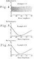
- Fig. 1 is a graph showing the results of the measurements of the spectral reflectance in Example 4-1.
- Fig. 2 is a graph showing the results of the measurements of the spectral reflectance in Example 4-2.
- Fig. 3 is a graph showing the results of the measurements of the spectral reflectance in Example 4-3.
- Fig. 4 is a graph showing the results of the measurements of the spectral reflectance in Example 4-4.
- Fig. 5 is a graph showing the results of the measurements of the spectral reflectance in Example 4-5.
- Fig. 6 is a graph showing the results of the measurements of the spectral reflectance in Example 4-6.
- Fig. 7 is a graph showing the results of the measurements of the spectral reflectance in Example 4-7.
- Fig. 8 is a graph showing the results of the measurements of the spectral reflectance in Example 4-8.
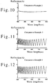
- Fig. 9 is a graph showing the results of the measurements of the spectral reflectance in Comparative Example 1.
- Fig. 10 is a graph showing the results of the measurements of the spectral reflectance in Comparative Example 2.
- Fig. 11 is a graph showing the results of the measurements of the spectral reflectance in Comparative Example 3.
- Fig. 12 is a graph showing the results of the measurements of the spectral reflectance in Comparative Example 4.
- Fig. 13 is a graph showing the results of the measurements of the spectral reflectance in Example 5-1.
- Fig. 14 is a graph showing the results of the measurements of the spectral reflectance in Example 5-2.
- Fig. 15 is a graph showing the results of the measurements of the spectral reflectance in Example 5-3.
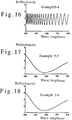
- Fig. 16 is a graph showing the results of the measurements of the spectral reflectance in Example 5-4.
- Fig. 17 is a graph showing the results of the measurements of the spectral reflectance in Example 5-5.
- Fig. 18 is a graph showing the results of the measurements of the spectral reflectance in Example 5-6.
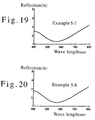
- Fig. 19 is a graph showing the results of the measurements of the spectral reflectance in Example 5-7.
- Fig. 20 is a graph showing the results of the measurements of the spectral reflectance in Example 5-8.
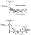
- Fig. 21 is a graph showing the results of the measurements of the spectral reflectance in Comparative Example 5.
- Fig. 22 is a graph showing the results of the measurements of the spectral reflectance in Comparative Examples 6 and 7.
- the present fluorine-containing polyfunctional (meth)acrylate may be a fluorine-containing bifunctional (meth)acrylate having (meth)acryloyl groups and a hydroxyl group and represented by the formula (1a) wherein two of Y 1 , Y 2 and Y 3 stand for an acryloyl group or a methacryloyl group, and the remaining one of Y 1 ,Y 2 and Y 3 stands for a hydrogen atom (referred to hereinbelow as diester A); a fluorine-containing bifunctional (meth)acrylate having (meth)acryloyl groups and a hydroxyl group and represented by the formula (1b) wherein two of Y 1 , Y 2 and Y 3 stand for an acryloyl group or a methacryloyl group, and the remaining one of Y 1 ,Y 2 and Y 3 stands for a hydrogen atom (referred to hereinbelow as diester B); a fluorine-containing trifunctional (meth)
- Preferred examples of diester A may include
- Preferred examples of diester B may include
- Preferred examples of triester A may include
- Preferred examples of triester B may include
- diester A, diester B, triester A, and triester B may be used alone or as a mixture as a starting material for a resin with low refractive index (a mixture of diester A and diester B is referred to as "diester mixture”, a mixture of triester A and triester B is referred to as “triester mixture”, and a mixture of diester and triester, or the diester mixture and the triester mixture are collectively referred to as "ester mixture” in some cases hereinbelow.
- the first method includes the steps of (a) reacting carboxylic acid having two hydroxymethyl groups represented by the following formula (2) (referred to hereinbelow as “carboxylic acid C”) and fluorine-containing diepoxide represented by the following formula (3) (referred to hereinbelow as “epoxide D”) in the presence of a catalyst according to an ordinary ring-opening reaction to obtain a mixture of hydroxyfluoroalkyl 2,2-bis(hydroxymethyl)carboxylates represented by the following formulae (4) and (5) (both respectively referred to hereinbelow as "ester E"), and (b) esterifying the ester E's with (meth)acryloylchloride, to produce an ester mixture.
- carboxylic acid having two hydroxymethyl groups represented by the following formula (2) referred to hereinbelow as “carboxylic acid C”
- fluorine-containing diepoxide represented by the following formula (3) referred to hereinbelow as “epoxide D”
- carboxylic acid C for use in the reaction (a) may include
- reaction (a) For reacting carboxylic acid C and epoxide D in reaction (a), it is preferred to charge 0.8 to 5mol, more preferably 1.0 to 1.8mol of carboxylic acid C per 1mol of epoxide D.
- Examples of the catalyst used in reaction (a) may include tertiary amines such as triethylamine or benzyldimethylamine; or quaternary ammonium salts such as tetraethylammonium bromide or tetramethylammonium bromide.
- the amount of the catalyst is preferably 0.001 to 5% by weight, more preferably 0.01 to 2.5 % by weight of the total weight of the reaction mixture.
- the temperature for the reaction (a) is preferably 40 to 200 °C, more preferably 80 to 120 °C.
- the duration of the reaction is preferably 1 to 48 hours, more preferably 2 to 12 hours.
- the mixture of ester E's obtained by the reaction (a) may be, before it is subjected to step (b), dissolved in an organic solvent such as chloroform, methylene chloride, trifluoromethylbenzene, ethyl acetate or mixtures thereof, and washed with an alkaline aqueous solution such as sodium hydroxide or sodium carbonate, for removing the catalyst, depending on the need.
- the mixture of ester E's may be purified by vacuum distillation, recrystallization, or column chromatography.
- ester E and (meth)acryloylchloride in reaction (b) it is preferred to charge 1.6 to 10mol, more preferably 2.0 to 4.0mol of (meth)acryloylchloride per 1mol of ester E.
- a triester mixture it is preferred to charge 2.4 to 15mol, more preferably 3.0 to 6.0mol of (meth)acryloylchloride per 1mol of ester E.
- base such as tertiary alkylamine, for example, triethylamine or benzyldimethylamine, or pyridine may be added to the reaction mixture for capturing hydrochloric acid generated during the reaction.
- the amount of base is preferably 1.6 to 10.0mol, more preferably 2.0 to 4.5mol per 1mol of ester E, for producing a diester mixture.
- the amount of base is preferably 2.4 to 15.0mol, more preferably 3.0 to 7.0 per 1mol of ester E.
- reaction (b) it is preferred to proceed with reaction (b) in a suitable solvent.
- a suitable solvent may include chloroform, methylene chloride, trifluoromethylbenzene, or mixtures thereof.
- the amount of the solvent is preferably 20 to 2000 parts by weight, more preferably 100 to 500 parts by weight based on 100 parts by weight of the total amount of ester E, (meth) acryloylchloride, and the base.
- the temperature for reaction (b) is preferably -60 to 20 °C, more preferably -40 to 0 °C, and the duration of reaction (b) is preferably 0.1 to 12 hours, more preferably 0.5 to 2 hours.
- the resulting system including the generated ester mixture may be subjected to a variety of treatments depending on the need. For example, a small amount of alcohols such as methanol or ethanol, or water may be added to the reaction system for decomposing the excess (meth)acryloylchloride in the reaction system.
- the reaction system may also be washed with an acid aqueous solution such as diluted hydrochloric acid.
- the reaction system may also be subjected to purification such as vacuum distillation, recrystallization or column chromatography.
- a polymerization inhibitor such as hydroquinone, hydroquinone monoethyl ether, or tert-butylcatechol to the system for inhibiting polymerization.
- the amount of the polymerization inhibitor is preferably 0.001 to 2 % by weight, more preferably 0.005 to 0.2 % by weight of the total weight of the mixture resulting from the reaction (c).
- the diester mixture generated by the reaction (b) is usually a mixture of four structural isomers composed of two sorts of diester A and two sorts of diester B.
- the isomers are diester A 1 represented by the formula (6), diester A 2 represented by the formula (7), diester B 1 represented by the formula (8), and diester B 2 represented by the formula (9): (in the formulae, X, Y 1 , Y 2 , Y 3 and Z are the same as X, Y 1 , Y 2 , Y 3 and Z in the formula (1))
- the objective compound may be obtained by separation and isolation of diester A 1 , diester A 2 , diester B 1 or diester B 2 , or diester A consisting of diester A 1 and diester A 2 , or diester B consisting of diester B 1 and diester B 2 .
- the resulting triester mixture is a mixture of structural isomers triester A and triester B.
- the objective compound may be obtained by separating and isolating the triester A and triester B from the triester mixture.
- the separating and isolating methods may include, for example, liquid chromatography for separation.
- the second method includes the steps of (c) producing 2,2-bis((meth)acryloyloxymethyl)carboxylic acid represented by the following formula (10) (referred to hereinbelow as carboxylic acid F) from the aforementioned carboxylic acid C by a method, for example, as described in Japanese Laid-open Patent Application No.
- 63-99038 that is, by reacting the aforementioned carboxylic acid C with (meth)acrylic acid, (meth)acryloylchloride or (meth)acrylate in the presence of, if needed, any suitable catalyst (in the formula, Y 1 , Y 2 and Z are the same as Y 1 , Y 2 and Z in the formula (1)), and (d) reacting the carboxylic acid F with the aforementioned epoxide D in the presence of a catalyst according to an ordinary ring-opening reaction, to obtain an ester mixture.
- the resulting ester mixture is a mixture of diester A 1 represented by the formula (6) and diester B 1 represented by the formula (8).
- reaction (c) For reacting carboxylic acid C and (meth)acryloylchloride in reaction (c), it is preferred to charge 1.6 to 10mol, more preferably 2.0 to 4.0mol of (meth)acryloylchloride per 1mol of carboxylic acid C.
- base such as tertiary alkylamine, for example, triethylamine or benzyldimethylamine, or pyridine may be added to the reaction system for capturing the hydrochloric acid generated during the reaction.
- the amount of base is preferably 1.6 to 10mol, more preferably 2.0 to 4.5mol per 1mol of carboxylic acid C.
- reaction (c) it is preferred to proceed with reaction (c) in a suitable solvent.
- a suitable solvent may include chloroform, methylene chloride, trifluoromethylbenzene, and the like.
- the amount of the solvent is preferably 20 to 2000 parts by weight, more preferably 100 to 500 parts by weight based on 100 parts by weight of the total amount of carboxylic acid C, (meth)acryloylchloride, and the base.
- the temperature for reaction (c) is preferably -60 to 20 °C, more preferably -40 to 0 °C, and the duration of reaction (c) is preferably 0.1 to 12 hours, more preferably 0.5 to 2 hours.
- Carboxylic acid F produced by the reaction (c) may be subjected to a variety of treatments depending on the need, before subsequent treatment (d). For example, a small amount of alcohols such as methanol or ethanol or water may be added to the reaction system for decomposing the excess (meth)acryloylchloride in the reaction system. Carboxylic acid F may also be washed with an acid aqueous solution such as diluted hydrochloric acid. Carboxylic acid F may also be purified by vacuum distillation, recrystallization or column chromatography.
- a polymerization inhibitor such as hydroquinone, hydroquinone monoethyl ether, or tert-butylcatechol to the system for inhibiting polymerization.
- the amount of the polymerization inhibitor is preferably 0.001 to 2.0 % by weight, more preferably 0.005 to 0.2 % by weight of the total weight of the mixture after the reaction.
- the mixing ratio of carboxylic acid F is preferably 0.8 to 5mol, more preferably 1.0 to 1.8mol per 1mol of epoxide D.
- Examples of the catalyst used in reaction (d) may include publicly known catalysts such as tertiary amines including triethylamine or benzyldimethylamine; or quaternary ammonium salts including tetraethylammonium bromide or tetramethylammonium bromide.
- the amount of the catalyst is preferably 0.001 to 5.0% by weight, more preferably 0.01 to 2.5 % by weight of the total weight of the reaction mixture.
- a polymerization inhibitor may include hydroquinone, hydroquinone monoethyl ether, or tert-butylcatechol.
- the amount of the polymerization inhibitor is preferably 0.001 to 2 % by weight, more preferably 0.005 to 0.2 % by weight of the total weight of the reaction mixture.
- the temperature for the reaction (d) is preferably 40 to 200 °C, more preferably 80 to 120 °C.
- the duration of the reaction (d) is preferably 1 to 48 hours, more preferably 2 to 12 hours.
- the resulting mixture containing the generated diester mixture may be subjected to a variety of treatments depending on the need before use.
- the mixture may be dissolved in an organic solvent such as chloroform, methylene chloride or trifluoromethylbenzene, and then washed with an alkaline aqueous solution such as sodium hydroxide or sodium carbonate, for removing the catalyst.
- the mixture may be purified by vacuum distillation, recrystallization, column chromatography, and the like, depending on the need. In the vacuum distillation, it is preferred to add a polymerization inhibitor such as hydroquinone, hydroquinone monoethyl ether, or tert-butylcatechol to the mixture for inhibiting polymerization.
- the amount of the polymerization inhibitor is preferably 0.001 to 2 % by weight, more preferably 0.005 to 0.2 % by weight of the total weight of the mixture resulting from the reaction.
- a triester mixture may be produced by (e) esterifying the diester mixture obtained by the reactions (c) and (d) with one equivalent of additional (meth)acryloylchloride.
- reaction (e) For reacting the diester mixture and (meth)acryloylchloride in reaction (e), it is preferred to charge 0.8 to 5mol, more preferably 1.0 to 2.0mol of (meth)acryloylchloride per 1mol of the diester mixture.
- base such as tertiary alkylamine, for example, triethylamine or benzyldimethylamine, or pyridine may be added to the reaction system for capturing hydrochloric acid generated during the reaction.
- the amount of base is preferably 0.8 to 5.0mol, more preferably 1.0 to 2.5mol per 1mol of the diester mixture.
- reaction (e) it is preferred to proceed with reaction (e) in a suitable solvent.
- a suitable solvent may include chloroform, methylene chloride, trifluoromethylbenzene, and the like.
- the amount of the solvent is preferably 20 to 2000 parts by weight, more preferably 100 to 500 parts by weight based on 100 parts by weight of the total amount of the diester mixture, (meth) acryloylchloride, and the base.
- the temperature for reaction (e) is preferably -60 to 20 °C, more preferably -40 to 0 °C, and the duration of reaction (e) is preferably 0.1 to 12 hours, more preferably 0.5 to 2 hours.
- the resulting system containing generated ester mixture may be subjected to a variety of treatments depending on the need. For example, a small amount of alcohols such as methanol or ethanol, or water may be added to the reaction system for decomposing the excess (meth)acryloylchloride in the reaction system.
- the reaction system may also be washed with an acid aqueous solution such as diluted hydrochloric acid.
- the reaction system may also be subjected to purification such as vacuum distillation, recrystallization or column chromatography.
- a polymerization inhibitor such as hydroquinone, hydroquinone monoethyl ether, or tert-butylcatechol to the system for inhibiting polymerization.
- the amount of the polymerization inhibitor is preferably 0.001 to 2 % by weight, more preferably 0.005 to 0.2 % by weight of the total weight of the mixture resulting from the reaction (e).
- the triester mixture generated by the reaction (e) is a mixture of structural isomers triester A and triester B.
- the objective compound may be obtained by separation and isolation of triester A and triester B. The separation and isolation may be performed, for example, by liquid chromatography for separation.
- the fluorine-containing polyfunctional (meth)acrylate itself of the present invention may be cured by cross-linking to produce a cured film having excellent abrasion resistance and adhesion, and may be used alone or as a mixture.
- the composition of the present invention contains the fluorine-containing polyfunctional (meth)acrylate, or both the fluorine-containing polyfunctional (meth)acrylate and powders of an inorganic compound.
- the fluorine-containing polyfunctional (meth)acrylate is a compound represented by the formula (1), and may specifically be a fluorine-containing polyfunctional (meth)acrylate selected from the group consisting of the aforementioned diester A 1 , diester A 2 , diester B 1 , diester B 2 , triester A, triester B and mixtures thereof (sometimes collectively referred to as polyfunctional ester A hereinbelow).
- the mixture various ester mixtures obtained during the aforementioned method of producing the polyfunctional ester A may be directly used.
- the content of polyfunctional ester A is 5 to 100 % by weight, preferably 10 to 100 % by weight of the total weight of the composition.
- the content of the powders of the inorganic compound is preferably less than 90 % by weight of the total weight of the composition.
- the powders of the inorganic compound is preferably a compound having the refractive index of 1.5 or lower.
- powders of magnesium fluoride (refractive index 1.38), silicon oxide (refractive index 1.46), aluminum fluoride (refractive index 1.33 to 1.39), calcium fluoride (refractive index 1.44), lithium fluoride (refractive index 1.36 to 1.37), sodium fluoride (refractive index 1.32 to 1.34), or thorium fluoride (refractive index 1.45 to 1.50) are preferable.
- the particle size of the powders is preferably sufficiently smaller than the wave length of the visible radiation for the purpose of ensuring the transparency of the low refractivity material. Specifically, the particle size is preferably not larger than 100 nm, more preferably not larger than 50 nm.
- the inorganic powders is used preferably in the form of an organic sol in which the powders are previously dispersed in an organic dispersion medium, for preventing the decreasing of dispersion stability in the composition and of adhesion in the low refractivity material.
- the surface of the inorganic powder composition may be modified with various coupling agents.
- the various coupling agents may include, for example, silicide substituted by organic residues; alkoxides of metals such as aluminum, titanium, zirconium, antimony, or mixtures thereof; salts of organic acids; and coordination compounds combined with compounds which can be coordinated.
- thermosetting monomers and energy-beam curable monomers may include polyfunctional monomers having two or more polymerizable unsaturated groups, for example, polyalkylene glycol di(meth)acrylate such as dipentaerythritol hexa(meth)acrylate, dipentaerythritol penta(meth)acrylate, dipentaerythritol tetra(meth)acrylate, pentaerythritol tetra(meth)acrylate, pentaerythritol tri(meth)acrylate, pentaerythritol di(meth)acrylate, ditrimethylolpropane tetra(meth)acrylate, ditrimethylolpropane tri(meth)acrylate, di
- composition of the present invention may optionally contain monofunctional (meth)acrylate as long as the desired effect of the present invention is not deteriorated.
- monofunctional (meth)acrylate may preferably be fluorine-containing monofunctional (meth)acrylate in view of the purpose of lowering the refractive index of the monomer composition, such as 2,2,2-trifluoroethyl (meth)acrylate, 2,2,3,3,3-pentafluoropropyl (meth)acrylate, 2,2,3,3,4,4,4-heptafluorobutyl (meth)acrylate, 2,2,3,3,4,4,5,5,5-nonafluoropentyl (meth)acrylate, 2,2,3,3,4,4,5,5,6,6,6-undecafluorohexyl (meth)acrylate, 2,2,3,3,4,4,5,5,6,6,7,7,7-tridecafluoroheptyl (meth)acrylate, 2,2,3,3,4,4,5,5,6,6,7,7,8,8,8-pent
- the composition of the present invention may also contain, if necessary, fluorine-containing bifunctional (meth)acrylate other than the diester mixture as a curing material as long as the desired effect of the present invention is not deteriorated.
- fluorine-containing bifunctional (meth)acrylate other than the diester mixtures may include 2,2,2-trifluoroethylethylene glycol di(meth)acrylate, 2,2,3,3,3-pentafluoropropylethylene glycol di(meth)acrylate, 2,2,3,3,4,4,4-heptafluorobutylethylene glycol di(meth)acrylate, 2,2,3,3,4,4,5,5,5-nonafluoropentylethylene glycol di(meth)acrylate, 2,2,3,3,4,4,5,5,6,6,6-undecafluorohexylethylene glycol di(meth)acrylate, 2,2,3,3,4,4,5,5,6,6,7,7,7-tridecafluoroheptylethylene glycol di(meth)acryl
- the composition of the present invention may optionally be mixed with a polymer for improving the film forming property.
- the polymer to be added is not particularly limited, but preferably a polymer of fluorine-containing (meth)acrylate, or a copolymer of fluorine-containing (meth)acrylate with other monomers.
- the mixing ratio of the polymer is preferably 25 parts by weight or less, more preferably 10 parts by weight or less based on 100 parts by weight of the curing materials in the monomer composition.
- the low refractivity material of the present invention is prepared by curing the above-mentioned composition by polymerization, and has the refractive index of 1.49 or lower, more preferably 1.35 to 1.49.
- the curing by polymerization may be carried out by optionally admixing a curing initiator and/or a solvent such as isopropylalcohol or toluene to the monomer composition; applying the resulting mixture to a substrate such as a transparent substrate by an ordinary coating method such as roll coating method, gravure coating method, dip coating method, or spin coating method; drying; and curing by heating or irradiation with active energy beam such as ultraviolet ray, electron beam, or radio active ray.
- the conditions for curing by polymerization may suitably be selected depending on the curing materials in the composition. When the low refractivity material is formed into a film, the film thickness may suitably be selected depending on the purpose.
- the curing initiator may include azo radical polymerization initiators such as azobisisobutyronitrile, azobiscyclohexanecarbonitrile, or azobisvaleronitrile; radical polymerization initiators of organic peroxide type such as benzoyl peroxide, tert-butylhydroperoxide, cumene peroxide, or diacylperoxide; or photopolymerization initiators such as benzoin compounds including benzoin, benzoin methyl ether, benzoin ethyl ether, or benzoin isopropyl ether, carbonyl compounds including benzyl, benzophenone, acetophenone, or Michler's ketone, azo compounds including azobisisobutyronitrile or azodibenzoyl, or a mixture of ⁇ -diketone and a tertiary amine.
- the amount of the curing initiator may be 0.01 to 10 % by weight of the total weight of the cu
- the reflection reducing film of the present invention has a transparent substrate and a layer of the low refractivity material.
- the layer of the low refractivity material preferably has a suitable thickness.
- the suitable thickness is preferably selected so that the wave length which indicated the minimum reflectance of the reflection reducing film is usually 420 to 720 nm, more preferably 520 to 620 nm.
- the kind of the transparent substrate is not particularly limited as long as the substrate is transparent.
- a PET (polyethylene terephthalate) film, a TAC (triacetyl cellulose) film, an acryl film, or a polycarbonate film may be used.
- the reflection reducing film of the present invention may be composed of the transparent substrate and the layer of the low refractivity material thereon, or of the transparent substrate, the layer of the low refractivity material, and at least one material layer therebetween.
- the material layer may be a layer of a high refractivity material for improving the reflection reducing effect.
- the layer of the high refractivity material preferably has the refractive index of 1.55 or higher, and the thickness of the layer may preferably be selected so that the wave length which indicated the maximum reflectance of the film provided with the layer of the high refractivity material is usually 400 to 900 nm.
- the transparent substrate may be provided with one layer of the low refractivity material and one layer of the high refractivity material, or it may be provided with two or more layers of each material.
- the layers of the low refractivity material and the high refractivity material may be laminated alternately, with the outermost layer being of the low refractivity material.
- each layer of the low refractivity material or the high refractivity material may be made of the same or different materials.
- the layer of the low refractivity material may be formed by optionally admixing a curing initiator and/or a solvent such as isopropylalcohol or toluene to the fluorine-containing composition; applying the resulting mixture to a substrate such as a transparent substrate by an ordinary coating method such as roll coating method, gravure coating method, dip coating method, or spin coating method; drying; and curing by heating or irradiation with active energy beam such as ultraviolet ray, electron beam, or radio active ray.
- the conditions for curing by polymerization may suitably be selected depending on the curing materials in the composition.
- the layer of the high refractivity material may be formed in the same way.
- the reflection reducing film of the present invention may be provided with a hard coating for further improving the abrasion resistance of the reflection reducing film.
- the hard coating may be provided between the laminated layers of the low refractivity material and the high refractivity material and the transparent substrate.
- the kind of the hard coating is not particularly limited, and may be made of an ordinary resin for hard coating prepared from the polyfunctional monomer having two or more polymerizable unsaturated groups. However, if the difference in the refractive index of the transparent substrate and the hard coating is too large, reflection will occur at the interface therebetween. Thus, the difference in the refractive index of the transparent substrate and the hard coating is preferably kept as small as possible.
- the thickness of the hard coating is preferably 1 to 10 ⁇ m, more preferably 3 to 5 ⁇ m.
- the method of forming the hard coating is not particularly limited, and may include applying the hard coating material to a substrate such as a transparent substrate by an ordinary coating method such as roll coating method, gravure coating method, dip coating method, or spin coating method; drying; and curing by an ordinary method using energy beam or heat.
- an ordinary coating method such as roll coating method, gravure coating method, dip coating method, or spin coating method
- drying and curing by an ordinary method using energy beam or heat.
- the fluorine-containing polyfunctional (meth)acrylate of the preset invention has a plurality of (meth)acryloyl groups, it is cured by cross-linking polymerization to acquire three-dimensional net work structure, and gives a cured film having high surface hardness and excellent abrasion resistance, wear resistance, heat resistance, and weatherability. Further, the diester mixture having a hydroxyl group can improve the adhesion of the cured coating film.
- the obtained cured product has superior light transmittance and low refractive index as well as excellent adhesion, so that it is useful as a resin with low refractive index for antireflection films or clad materials for optical fibers which are required to have superior abrasion resistance and adhesion.
- the composition of the present invention contains the particular fluorine-containing polyfunctional (meth)acrylate
- the cured product prepared by polymerizing the composition has the properties of both the low refractive index and the hardness of (meth)acrylate, and the composition can be formed into a film by applying on a substrate and cured by polymerization, thereby preparing the low refractivity material of the present invention.
- the low refractivity material of the present invention has the properties of both the low refractive index and the hardness of (meth)acrylate, and has low refractive index and high surface hardness. Further, by using the diester mixture having a hydroxyl group, its adhesion to other materials is further improved.
- composition of the present invention may further contain powders of an inorganic compound, in addition to the particular fluorine-containing polyfunctional (meth)acrylate.
- an inorganic compound in addition to the particular fluorine-containing polyfunctional (meth)acrylate.
- the reflection reducing film of the present invention is provided with a layer of the low refractivity material, it has low refractive index, high surface hardness, and high adhesion, and may be applied to a variety of usage. Accordingly, by using the composition of the present invention, reflection reducing films having a layer of the low refractivity material with larger area may be produced continuously and effectively at a low cost, compared to the conventional vapor deposition of magnesium fluoride.
- the precipitate is separated by filtration and then dissolved in 1000 ml of ethyl acetate, and the solution thus obtained was washed three times with 1000 ml of water. The solvent was removed from the washed solution under reduced pressure to obtain white crystals.
- the crystals are believed to be a mixture of compounds having structures represented by the following formulae (11) and (12).
- a portion of product G was further separated by high speed liquid chromatography. Separation was performed employing TSK gel Silica-60 (internal diameter of 21.5 mm: length of 300 mm: manufactured by TOSOH CORP.) as a column, and a mixed solvent of ethyl acetate/n-hexane (volume ratio 1:5), at flow rate of 5 ml per minute. For detection, an ultraviolet detector was employed at the wave length of 230nm.
- the obtained compounds G-1, G-2, G-3 and G-4 were the compounds having the structures represented by the following formulae (13), (14), (15) and (16), respectively.
- the results of 1 H-NMR, 19 F-NMR, and Exact MS of these compounds thus obtained are shown below together with the structural formulae thereof.
- Example 1-1 A portion of product H was separated by high speed liquid chromatography in the same way as in Example 1-1.
- the obtained compounds H-1, H-2, H-3 and H-4 were the compounds having the structures represented by the following formulae (19), (20), (21) and (22), respectively.
- the results of 1 H-NMR, 19 F-NMR, and Exact MS of these compounds thus obtained are shown below together with the structural formulae thereof.
- Example 1-1 A portion of product I was further separated by high speed liquid chromatography in the same way as in Example 1-1.
- the obtained compounds I-1 and I-2 were the compounds having the structures represented by the above formulae (13) and (15), respectively.
- the results of 1 H-NMR, 19 F-NMR, and Exact MS of the obtained compounds are shown below.
- the precipitate was separated by filtration and then dissolved in 1000 ml of ethyl acetate, and the solution thus obtained was washed three times with 1000 ml of water. The solvent was removed from the washed solution under reduced pressure to obtain white crystals. These white crystals are believed to be a mixture of compounds having structures represented by the above formulae (11) and (12).
- Example 1-1 A portion of product J was further separated by high speed liquid chromatography in the same way as in Example 1-1.
- the compounds J-1 and J-2 obtained as the result of the separation were the compounds having the structures represented by the following formulae (24) and (25), respectively.
- the results of 1 H-NMR, 19 F-NMR, and Exact MS of the compounds thus obtained are shown below together with the structural formulae thereof.
- Example 1-1 A portion of product K was separated by high speed liquid chromatography in the same way as in Example 1-1.
- the obtained compounds K-1 and K-2 were the compounds having the structures represented by the following formulae (26) and (27), respectively.
- the results of 1 H-NMR, 19 F-NMR, and Exact MS of the compounds thus obtained are shown below together with the structural formulae thereof.
- Product I was obtained in the same way as in Example 1-3.
- Into a reactor equipped with a stirrer, a thermometer, a gas introducing tube and a dropping funnel 574 g of the product I, 151.8 g of triethylamine, and 1000 ml of chloroform were charged. Under ice cooling, 159.8 g (1.5 mol) of acryloylchloride were dissolved in 150 ml of chloroform, and the resulting solution was added dropwise to the reaction liquid from the dropping funnel while the temperature of the reaction liquid was kept below 5°C. After the completion of dropping, the reaction liquid was kept under ice cooling and stirred for two hours.
- Example 1-1 A portion of product L was further separated by high speed liquid chromatography in the same way as in Example 1-1.
- the compounds L-1 and L-2 obtained as the result of separation were the compounds having the structures represented by the formulae (24) and (25), respectively.
- the results of 1 H-NMR, 19 F-NMR, and Exact MS of the compounds thus obtained are shown below.
- reaction liquid M the silane coupling agent modified a part of the surface of colloidal silica.
- a portion of the reaction liquid M was put on a Schale, and dried at 120 °C for two hours, and the weight before and after the drying was measured for measuring the solid content, which was found to be 44.6 %.
- the film was cured by irradiating the film with ultraviolet ray by an ultraviolet irradiator manufactured by IWASAKI ELECTRIC CO., LTD. at 800 mJ/cm 2 to form a hard coating, thereby preparing a PET film with hard coating (abbreviated as HC-PET hereinbelow).
- a hard coating was formed on a TAC film in the same way as in Preparation Example 1 to prepare a TAC film with hard coating (abbreviated as HC-TAC hereinbelow).
- HC-TAC hard coating
- 240 parts by weight of toluene dispersion containing 30 % zinc oxide powders (trade name "ZN-300", manufactured by SUMITOMO OSAKA CEMENT CO. LTD.), 28 parts by weight of trimethylolpropane triacrylate (abbreviated as TMPTA hereinbelow), 1 part by weight of "DAROCUR1116" (trade name, manufactured by E.
- acetophenone compound (abbreviated as "DAROCUR1116” hereinbelow) as a curing initiator, and 1900 parts by weight of toluene as a solvent were mixed together to prepare a coating liquid.
- the coating liquid was applied to the HC-TAC by dip coating method (at pull-up rate of 100 mm/min.).
- the applied coating liquid was cured by irradiating with ultraviolet ray by an ultraviolet irradiator at 1000 mJ/cm 2 to form a layer of a high refractivity material, thereby preparing a TAC film with a layer of the high refractivity material (abbreviated as HR-TAC-A hereinbelow).
- a TAC film with a layer of the high refractivity material (abbreviated as HR-TAC-B hereinbelow) was prepared in the same way as in Preparation Example 2 except that the dip coating was carried out at the pull-out rate of 130 mm/min.
- TMMTA tetramethylolmethane tetraacrylate
- the applied coating liquids were irradiated with electron beam of the absorbed dose of 15 Mrad by an electron beam irradiator (manufactured by IWASAKI ELECTRIC CO., LTD.) at the accelerating voltage of 125 kV and the beam current of 35 mA to cure the applied compositions, thereby preparing reflection reducing PET films with a layer of the low refractivity material.
- the film thickness of the low refractivity material was adjusted with an instantaneous multi optical measurement system so that the wave length which indicated the minimum refractivity was 550 to 600 nm.
- the films thus obtained were subjected to the measurements of (a), (b), and (c), and the coating liquids thus obtained were subjected to the measurement of (d), each specified below.
- the spectral reflectance of the film was measured by an UV Spectrophotometer equipped with 5 degree specular reflectivity measuring attachment (manufactured by JAPAN SPECTROSCOPIC CO., LTD., trade name "U-best 35"). The measurement was effected on the coated surface, and the opposite surface of the film was roughened with a sandpaper for inhibiting reflection on the opposite surface. The results are shown in Figs. 1 and 2. The minimum reflectance of each film is shown in Table 1.
- the coating liquid was applied on a glass plate so that the dry thickness of the resulting coating film was 500 ⁇ m, and cured by irradiating with electron beam of the absorbed dose of 5 Mrad by an electron beam irradiator at the accelerating voltage of 175 kV and the beam current of 5 mA.
- the film thus obtained was peeled off of the glass plate, and the refractive index of the film was measured using Abbe's refractometer (manufactured by ATAGO CO., LTD.). The results are shown in Table 1.
- Example 1-2 and TMMTA were mixed together at the mixing ratio set forth in Table 1 to prepare compositions.
- Each of the compositions was mixed with 400 parts by weight of trifluoromethylbenzene as a solvent to prepare two kinds of coating liquids.
- each of the coating liquids was applied to HC-PET prepared in Preparation Example 1 with the micro gravure coater.
- the applied coating liquids were irradiated with electron beam of the absorbed dose of 15 Mrad by the electron beam irradiator to cure the applied compositions, thereby preparing reflection reducing PET films with a layer of the low refractivity material.
- the film thickness of the low refractivity material was adjusted in the same way as in Examples 4-1 and 4-2.
- the coating liquids and the reflection reducing films thus obtained were subjected to the same evaluation tests for spectral reflectance, minimum reflection, adhesion, abrasion resistance and refractive index as in Examples 4-1 and 4-2. The results are shown in Figs. 3 and 4 and Table 1.
- the applied coating liquids were irradiated three times with ultraviolet ray by an ultraviolet irradiator at 1000 mJ/cm 2 to cure the applied compositions, thereby preparing reflection reducing TAC films with laminated layers of the low refractivity material and the high refractivity material.
- the film thickness of the low refractivity material was adjusted in the same way as in Examples 4-1 and 4-2.
- the coating liquids and the reflection reducing films thus obtained were subjected to the same evaluation tests for spectral reflectance, minimum reflection, adhesion, abrasion resistance, and refractive index as in Examples 4-1 and 4-2. The results are shown in Figs. 5 and 6 and Table 1.
- the applied coating liquids were irradiated three times with ultraviolet ray by an ultraviolet irradiator at 1000 mJ/cm 2 to cure the applied compositions, thereby preparing reflection reducing TAC films with laminated layers of the low refractivity material and the high refractivity material.
- the film thickness of the low refractivity material was adjusted in the same way as in Examples 4-1 and 4-2.
- the coating liquids and the reflection reducing films thus obtained were subjected to the same evaluation tests for spectral reflectance, minimum reflection, adhesion, abrasion resistance, and refractive index as in Examples 4-1 and 4-2. The results are shown in Figs. 7 and 8 and Table 1.
- the applied coating liquid was irradiated with electron beam of the absorbed dose of 15 Mrad by the electron beam irradiator at the accelerating voltage of 125 kV and the beam current of 35 mA to cure the applied coating liquid, thereby preparing a reflection reducing PET film with a layer of the low refractivity material.
- the film thickness of the low refractivity material was adjusted in the same way as in Examples 4-1 and 4-2.
- the coating liquid and the reflection reducing film thus obtained were subjected to the same evaluation tests for spectral reflectance, minimum reflection, adhesion, abrasion resistance and refractive index, as in Examples 4-1 and 4-2. The results are shown in Fig. 11 and Table 1.
- F 8 DTA and TMMTA were mixed at the mixing ratio set forth in Table 1, and further mixed with 400 parts by weight of trifluoromethylbenzene as a solvent to prepare a coating liquid.
- the coating liquid was applied to HC-PET prepared in Preparation Example 1 with the micro gravure coater.
- the applied coating liquid was irradiated with electron beam of the absorbed dose of 15 Mrad by the electron beam irradiator at the accelerating voltage of 125 kV and beam current of 35 mA to cure the applied mixture, thereby preparing a reflection reducing PET film with a layer of the low refractivity material.
- the film thickness of the low refractivity material was adjusted in the same way as in Examples 4-1 and 4-2.
- the coating liquid and the reflection reducing film thus obtained were subjected to the same evaluation tests for spectral reflectance, minimum reflection, adhesion, abrasion resistance and refractive index as in Examples 4-1 and 4-2. The results are shown in Fig. 12 and Table 1.
- compositions were mixed with 400 parts by weight of trifluoromethylbenzene to prepare two kinds of coating liquids. Then, each of the coating liquids was applied to HC-PET prepared in Preparation Example 1 with the micro gravure coater.
- the applied coating liquids were irradiated with electron beam of the absorbed dose of 15 Mrad by an electron beam irradiator (manufactured by IWASAKI ELECTRIC CO., LTD.) at the accelerating voltage of 125 kV and the beam current of 35 mA to cure the applied compositions, thereby preparing reflection reducing PET films with a layer of the low refractivity material.
- the film thickness of the low refractivity material was adjusted in the same way as in Examples 4-1 and 4-2.
- the coating liquids and the reflection reducing films thus obtained were subjected to the same evaluation tests for spectral reflectance, minimum reflection, abrasion resistance and refractive index as in Examples 4-1 and 4-2.
- the results are shown in Figs. 13 and 14 and Table 2.
- compositions were mixed together at the mixing ratio set forth in Table 2 to prepare compositions.
- Each of the compositions was mixed with 400 parts by weight of trifluoromethylbenzene as a solvent to prepare two kinds of coating liquids. Then, each of the coating liquids was applied to HC-PET prepared in Preparation Example 1 with the micro gravure coater.
- the applied coating liquids were irradiated with electron beam of the absorbed dose of 15 Mrad by an electron beam irradiator (manufactured by IWASAKI ELECTRIC CO., LTD.) at the accelerating voltage of 125 kV and the beam current of 35 mA to cure the applied compositions, thereby preparing reflection reducing PET films with a layer of the low refractivity material.
- the film thickness of the low refractivity material was adjusted in the same way as in Examples 4-1 and 4-2.
- the coating liquids and the reflection reducing films thus obtained were subjected to the same evaluation tests for spectral reflectance, minimum reflection, abrasion resistance and refractive index as in Examples 4-1 and 4-2. The results are shown in Figs. 15 and 16 and Table 2.
- compositions were mixed together at the mixing ratio set forth in Table 2 to prepare compositions.
- Each of the compositions was mixed with 400 parts by weight of trifluoromethylbenzene as a solvent to prepare two kinds of coating liquids.
- each of the coating liquids was applied to HR-TAC-A prepared in Preparation Example 2 with the micro gravure coater.
- Each of the applied coating liquids was irradiated three times with ultraviolet ray by an ultraviolet irradiator at 1000 mJ/cm 2 to cure the coating liquid, thereby preparing reflection reducing films with a layer of the low refractivity material.
- the film thickness of the low refractivity material was adjusted in the same way as in Examples 4-1 and 4-2.
- the coating liquids and the reflection reducing films thus obtained were subjected to the same evaluation tests for spectral reflectance, minimum reflection, abrasion resistance and refractive index as in Examples 4-1 and 4-2. The results are shown in Figs. 17 and 18 and Table 2.
- compositions were mixed together at the mixing ratio set forth in Table 2 to prepare compositions.
- Each of the compositions was mixed with 400 parts by weight of trifluoromethylbenzene as a solvent to prepare two kinds of coating liquids.
- each of the coating liquids was applied to HR-TAC-B prepared in Preparation Example 3 with the micro gravure coater.
- Each of the applied coating liquids was irradiated three times with ultraviolet ray by an ultraviolet irradiator at 1000 mJ/cm 2 to cure the coating liquid, thereby preparing reflection reducing films with a layer of the low refractivity material.
- the film thickness of the low refractivity material was adjusted in the same way as in Examples 4-1 and 4-2.
- the coating liquids and the reflection reducing films thus obtained were subjected to the same evaluation tests for spectral reflectance, minimum reflection, abrasion resistance and refractive index as in Examples 4-1 and 4-2. The results are shown in Figs. 19 and 20 and Table 2.
- heptadecafluorodecyl acrylate (abbreviated as F 17 A hereinbelow ) and 400 parts by weight of trifluoromethylbenzene as a solvent were mixed together to prepare a coating liquid. Then, the coating liquid was applied to HC-PET prepared in Preparation Example 1 with the micro gravure coater.
- the applied coating liquid was irradiated with electron beam of the absorbed dose of 15 Mrad by an electron beam irradiator (manufactured by IWASAKI ELECTRIC CO., LTD.) at the accelerating voltage of 125 kV and the beam current of 35 mA to cure the applied composition, thereby preparing a reflection reducing PET film with a layer of the low refractivity material.
- the film thickness of the low refractivity material was adjusted in the same way as in the Examples 4-1 and 4-2.
- the coating liquid and the reflection reducing film thus obtained were subjected to the same evaluation tests for spectral reflectance, minimum reflection, abrasion resistance and refractive index as in Examples 4-1 and 4-2. The results are shown in Figs. 21 and Table 2.
Landscapes
- Chemical & Material Sciences (AREA)
- Organic Chemistry (AREA)
- Physics & Mathematics (AREA)
- Health & Medical Sciences (AREA)
- Chemical Kinetics & Catalysis (AREA)
- Medicinal Chemistry (AREA)
- Polymers & Plastics (AREA)
- General Physics & Mathematics (AREA)
- Optics & Photonics (AREA)
- Addition Polymer Or Copolymer, Post-Treatments, Or Chemical Modifications (AREA)
- Organic Low-Molecular-Weight Compounds And Preparation Thereof (AREA)
Applications Claiming Priority (13)
| Application Number | Priority Date | Filing Date | Title |
|---|---|---|---|
| JP14713996 | 1996-06-10 | ||
| JP14713996 | 1996-06-10 | ||
| JP147139/96 | 1996-06-10 | ||
| JP24496396 | 1996-09-17 | ||
| JP24496396 | 1996-09-17 | ||
| JP244963/96 | 1996-09-17 | ||
| JP29264096 | 1996-11-05 | ||
| JP29264096 | 1996-11-05 | ||
| JP292640/96 | 1996-11-05 | ||
| JP296509/96 | 1996-11-08 | ||
| JP29650996 | 1996-11-08 | ||
| JP29650996 | 1996-11-08 | ||
| PCT/JP1997/001952 WO1997047585A1 (en) | 1996-06-10 | 1997-06-09 | Fluorinated polyfunctional (meth)acrylate esters, compositions, low-refraction materials, and antireflection films |
Publications (3)
| Publication Number | Publication Date |
|---|---|
| EP0863128A1 true EP0863128A1 (de) | 1998-09-09 |
| EP0863128A4 EP0863128A4 (de) | 1998-09-30 |
| EP0863128B1 EP0863128B1 (de) | 2001-11-21 |
Family
ID=27472766
Family Applications (1)
| Application Number | Title | Priority Date | Filing Date |
|---|---|---|---|
| EP97924352A Expired - Lifetime EP0863128B1 (de) | 1996-06-10 | 1997-06-09 | Fluorierte polyfunktionelle (meth)acrylester,zusammensetzungen,materialien mit niedriger brechung und antireflektionsfilmen |
Country Status (6)
| Country | Link |
|---|---|
| EP (1) | EP0863128B1 (de) |
| KR (2) | KR100268166B1 (de) |
| CN (1) | CN1094923C (de) |
| DE (1) | DE69708456T2 (de) |
| TW (1) | TW363976B (de) |
| WO (1) | WO1997047585A1 (de) |
Cited By (10)
| Publication number | Priority date | Publication date | Assignee | Title |
|---|---|---|---|---|
| US6376572B1 (en) | 1999-06-03 | 2002-04-23 | Ausimont S.P.A. | Compositions for films having a low refractive index |
| WO2005049667A1 (ja) | 2003-11-21 | 2005-06-02 | Dainippon Ink And Chemicals, Inc. | 含フッ素光硬化性組成物 |
| WO2006073785A1 (en) * | 2004-12-30 | 2006-07-13 | 3M Innovative Properties Company | Low refractive index fluoropolymer compositions having improved coating and durability properties |
| WO2006073867A1 (en) * | 2004-12-30 | 2006-07-13 | 3M Innovative Properties Company | Low refractive index fluoropolymer coating compositions for use in antireflective polymer films |
| US7351471B2 (en) | 2000-12-06 | 2008-04-01 | 3M Innovative Properties Company | Fluoropolymer coating compositions with multifunctional fluoroalkyl crosslinkers for anti-reflective polymer films |
| EP2038353A4 (de) * | 2006-07-10 | 2009-07-29 | Lg Chemical Ltd | Uv-härtbares antireflexionsbeschichtungsmittel, davon gebrauch machender antireflexionsbeschichtungsfilm und sein herstellungsverfahren |
| US7615283B2 (en) | 2006-06-13 | 2009-11-10 | 3M Innovative Properties Company | Fluoro(meth)acrylate polymer composition suitable for low index layer of antireflective film |
| WO2007146686A3 (en) * | 2006-06-13 | 2010-05-27 | 3M Innovative Properties Company | Durable antireflective film with surface modified inorganic nanoparticles |
| US8231973B2 (en) | 2006-06-13 | 2012-07-31 | 3M Innovative Properties Company | Fluoro(meth)acrylate polymer composition suitable for low index layer of antireflective film |
| US8343624B2 (en) | 2006-06-13 | 2013-01-01 | 3M Innovative Properties Company | Durable antireflective film |
Families Citing this family (9)
| Publication number | Priority date | Publication date | Assignee | Title |
|---|---|---|---|---|
| JP4326283B2 (ja) * | 2003-07-10 | 2009-09-02 | セントラル硝子株式会社 | ヘキサフルオロカルビノール基を含有する新規な重合性アクリレート化合物及びそれを用いた高分子化合物 |
| KR101136358B1 (ko) | 2004-12-10 | 2012-04-18 | 삼성전자주식회사 | 컬러필터용 잉크 조성물 및 이를 이용하여 제조된컬러필터 기판, 및 이를 이용한 컬러필터 기판의 제조 방법 |
| JP4614813B2 (ja) * | 2005-04-12 | 2011-01-19 | 日揮触媒化成株式会社 | 低屈折率膜形成用組成物およびその硬化膜付基材 |
| KR100622214B1 (ko) * | 2005-04-19 | 2006-09-15 | 제일모직주식회사 | 저굴절층 코팅용 조성물 및 이를 이용한 반사방지 필름 |
| KR100756818B1 (ko) | 2006-01-31 | 2007-09-07 | 제일모직주식회사 | 저굴절층 코팅용 조성물, 이를 이용한 반사방지 필름 및 이반사방지 필름을 포함하는 화상 표시장치 |
| CN102873666B (zh) * | 2012-10-26 | 2015-09-16 | 林岳洪 | 气动钉枪 |
| JP6139448B2 (ja) * | 2014-03-26 | 2017-05-31 | 富士フイルム株式会社 | 光インプリント用硬化性組成物、パターン形成方法、パターンおよび含フッ素化合物 |
| WO2020049846A1 (ja) * | 2018-09-04 | 2020-03-12 | 株式会社スリーボンド | 硬化性樹脂組成物および硬化物 |
| CN113372744B (zh) * | 2021-05-21 | 2022-07-19 | 武汉工程大学 | 一种高折射率丙烯酸类光学材料及其制备方法和用途 |
Family Cites Families (3)
| Publication number | Priority date | Publication date | Assignee | Title |
|---|---|---|---|---|
| JPH0811777B2 (ja) * | 1986-02-27 | 1996-02-07 | 大日本インキ化学工業株式会社 | 低屈折率樹脂組成物 |
| JP2986122B2 (ja) * | 1991-04-19 | 1999-12-06 | 日本化薬株式会社 | ウレタン(メタ)アクリレート系液状樹脂組成物及び光ファイバー用コーティング剤 |
| JP2868188B2 (ja) * | 1991-05-31 | 1999-03-10 | 日本化薬株式会社 | (メタ)アクリル酸エステル、その製造方法、それを用いた樹脂組成物、光ファイバー用コーティング剤及び硬化物 |
-
1997
- 1997-06-06 TW TW086107841A patent/TW363976B/zh not_active IP Right Cessation
- 1997-06-09 KR KR1019980700867A patent/KR100268166B1/ko not_active Expired - Fee Related
- 1997-06-09 DE DE69708456T patent/DE69708456T2/de not_active Expired - Lifetime
- 1997-06-09 CN CN97190972A patent/CN1094923C/zh not_active Expired - Fee Related
- 1997-06-09 EP EP97924352A patent/EP0863128B1/de not_active Expired - Lifetime
- 1997-06-09 WO PCT/JP1997/001952 patent/WO1997047585A1/ja not_active Ceased
-
2000
- 2000-03-14 KR KR1020007002672A patent/KR100267631B1/ko not_active Expired - Fee Related
Cited By (18)
| Publication number | Priority date | Publication date | Assignee | Title |
|---|---|---|---|---|
| US6376572B1 (en) | 1999-06-03 | 2002-04-23 | Ausimont S.P.A. | Compositions for films having a low refractive index |
| US7351471B2 (en) | 2000-12-06 | 2008-04-01 | 3M Innovative Properties Company | Fluoropolymer coating compositions with multifunctional fluoroalkyl crosslinkers for anti-reflective polymer films |
| WO2005049667A1 (ja) | 2003-11-21 | 2005-06-02 | Dainippon Ink And Chemicals, Inc. | 含フッ素光硬化性組成物 |
| EP1698644A4 (de) * | 2003-11-21 | 2010-01-20 | Dainippon Ink & Chemicals | Fluorhaltige photohärtende zusammensetzung |
| CN100593124C (zh) * | 2004-12-30 | 2010-03-03 | 3M创新有限公司 | 涂敷性能和耐久性得到提高的低折射率含氟聚合物组合物 |
| WO2006073785A1 (en) * | 2004-12-30 | 2006-07-13 | 3M Innovative Properties Company | Low refractive index fluoropolymer compositions having improved coating and durability properties |
| WO2006073867A1 (en) * | 2004-12-30 | 2006-07-13 | 3M Innovative Properties Company | Low refractive index fluoropolymer coating compositions for use in antireflective polymer films |
| US7323514B2 (en) | 2004-12-30 | 2008-01-29 | 3M Innovative Properties Company | Low refractive index fluoropolymer coating compositions for use in antireflective polymer films |
| US7473462B2 (en) | 2004-12-30 | 2009-01-06 | 3M Innovative Properties Company | Low refractive index fluoropolymer compositions having improved coating and durability properties |
| CN101095064B (zh) * | 2004-12-30 | 2010-05-26 | 3M创新有限公司 | 用于减反射聚合物膜的低折射率含氟聚合物涂料组合物 |
| US7615283B2 (en) | 2006-06-13 | 2009-11-10 | 3M Innovative Properties Company | Fluoro(meth)acrylate polymer composition suitable for low index layer of antireflective film |
| WO2007146686A3 (en) * | 2006-06-13 | 2010-05-27 | 3M Innovative Properties Company | Durable antireflective film with surface modified inorganic nanoparticles |
| US8137801B2 (en) | 2006-06-13 | 2012-03-20 | 3M Innovative Properties Company | Durable antireflective film |
| US8231973B2 (en) | 2006-06-13 | 2012-07-31 | 3M Innovative Properties Company | Fluoro(meth)acrylate polymer composition suitable for low index layer of antireflective film |
| US8343624B2 (en) | 2006-06-13 | 2013-01-01 | 3M Innovative Properties Company | Durable antireflective film |
| US8470439B2 (en) | 2006-06-13 | 2013-06-25 | 3M Innovative Properties Company | Durable antireflective film |
| EP2038353A4 (de) * | 2006-07-10 | 2009-07-29 | Lg Chemical Ltd | Uv-härtbares antireflexionsbeschichtungsmittel, davon gebrauch machender antireflexionsbeschichtungsfilm und sein herstellungsverfahren |
| US8110249B2 (en) | 2006-07-10 | 2012-02-07 | Lg Chem, Ltd. | UV-curable antireflective coating composition, antireflective coating film using the same, and its manufacturing method |
Also Published As
| Publication number | Publication date |
|---|---|
| WO1997047585A1 (en) | 1997-12-18 |
| DE69708456T2 (de) | 2002-05-23 |
| KR19990036199A (ko) | 1999-05-25 |
| CN1094923C (zh) | 2002-11-27 |
| CN1198150A (zh) | 1998-11-04 |
| EP0863128B1 (de) | 2001-11-21 |
| KR100268166B1 (ko) | 2000-10-16 |
| EP0863128A4 (de) | 1998-09-30 |
| DE69708456D1 (de) | 2002-01-03 |
| TW363976B (en) | 1999-07-11 |
| KR100267631B1 (en) | 2000-09-15 |
Similar Documents
| Publication | Publication Date | Title |
|---|---|---|
| EP0863128B1 (de) | Fluorierte polyfunktionelle (meth)acrylester,zusammensetzungen,materialien mit niedriger brechung und antireflektionsfilmen | |
| EP0820980B1 (de) | Fluorierte polyfunktionelle (meth)acrylester, fluormonomer-zusammensetzung, material mit niedrigem brechungsindex und niedrig-reflektierender film | |
| US6087010A (en) | Fluorine-containing polyfunctional (meth) acrylate composition low refractivity material and reflection reducing film | |
| EP1140759A1 (de) | Polymerisierbare halogenierte vinylether | |
| JP2005097371A (ja) | フッ素含有樹脂組成物及び光学物品、並びにそれを用いた画像表示装置 | |
| EP0597887B1 (de) | Fluor enthaltende optische kunststofffaserkerne | |
| JP2005139363A (ja) | 含フッ素ポリマーとその製造方法、およびそれを含む硬化性樹脂組成物 | |
| JP3991730B2 (ja) | 重合性化合物およびその重合体 | |
| JP3724144B2 (ja) | 含フッ素単量体組成物及び減反射フィルム | |
| JP3724132B2 (ja) | 無機化合物微粒子含有含フッ素単量体組成物及び減反射フィルム | |
| JP3940086B2 (ja) | フッ素置換脂環基含有(メタ)アクリル酸エステルおよびその硬化物 | |
| JP3724097B2 (ja) | 含フッ素単量体組成物及び減反射フィルム | |
| JP2005008527A (ja) | 重合性アダマンタン化合物 | |
| JP2001318206A (ja) | 減反射材およびその用途 | |
| JP4003249B2 (ja) | 含フッ素化合物、光学薄膜およびそれを用いた反射防止性物品 | |
| JP4406966B2 (ja) | 含フッ素多官能(メタ)アクリル酸エステルおよび低屈折材料 | |
| JPH05209029A (ja) | 樹脂組成物およびそれを用いたプラスチッククラッド光ファイバー | |
| JPH10309770A (ja) | 透明導電性シート | |
| JPH03166206A (ja) | 光硬化性樹脂組成物およびそれを用いたプラスチッククラッド光ファイバー | |
| JPH10182558A (ja) | 含フッ素多官能(メタ)アクリル酸エステル | |
| EP0811174A1 (de) | Copolymere für optische fasern | |
| JPH10279531A (ja) | 含フッ素化合物、光学薄膜およびそれを用いた反射防止性物品 | |
| JPH10279529A (ja) | 含フッ素化合物、光学薄膜およびそれを用いた反射防止性物品 | |
| JPH09203801A (ja) | 光学薄膜およびそれを用いた反射防止性物品 | |
| JPH0693041B2 (ja) | プラスチツク光学材料 |
Legal Events
| Date | Code | Title | Description |
|---|---|---|---|
| PUAI | Public reference made under article 153(3) epc to a published international application that has entered the european phase |
Free format text: ORIGINAL CODE: 0009012 |
|
| 17P | Request for examination filed |
Effective date: 19980227 |
|
| AK | Designated contracting states |
Kind code of ref document: A1 Designated state(s): DE FR GB NL |
|
| A4 | Supplementary search report drawn up and despatched |
Effective date: 19980817 |
|
| AK | Designated contracting states |
Kind code of ref document: A4 Designated state(s): DE FR GB NL |
|
| GRAG | Despatch of communication of intention to grant |
Free format text: ORIGINAL CODE: EPIDOS AGRA |
|
| 17Q | First examination report despatched |
Effective date: 20001229 |
|
| GRAG | Despatch of communication of intention to grant |
Free format text: ORIGINAL CODE: EPIDOS AGRA |
|
| GRAH | Despatch of communication of intention to grant a patent |
Free format text: ORIGINAL CODE: EPIDOS IGRA |
|
| GRAH | Despatch of communication of intention to grant a patent |
Free format text: ORIGINAL CODE: EPIDOS IGRA |
|
| GRAA | (expected) grant |
Free format text: ORIGINAL CODE: 0009210 |
|
| AK | Designated contracting states |
Kind code of ref document: B1 Designated state(s): DE FR GB NL |
|
| REG | Reference to a national code |
Ref country code: GB Ref legal event code: IF02 |
|
| REF | Corresponds to: |
Ref document number: 69708456 Country of ref document: DE Date of ref document: 20020103 |
|
| ET | Fr: translation filed | ||
| PLBE | No opposition filed within time limit |
Free format text: ORIGINAL CODE: 0009261 |
|
| STAA | Information on the status of an ep patent application or granted ep patent |
Free format text: STATUS: NO OPPOSITION FILED WITHIN TIME LIMIT |
|
| 26N | No opposition filed | ||
| PGFP | Annual fee paid to national office [announced via postgrant information from national office to epo] |
Ref country code: GB Payment date: 20140618 Year of fee payment: 18 |
|
| PGFP | Annual fee paid to national office [announced via postgrant information from national office to epo] |
Ref country code: NL Payment date: 20140618 Year of fee payment: 18 Ref country code: DE Payment date: 20140619 Year of fee payment: 18 |
|
| PGFP | Annual fee paid to national office [announced via postgrant information from national office to epo] |
Ref country code: FR Payment date: 20140619 Year of fee payment: 18 |
|
| REG | Reference to a national code |
Ref country code: DE Ref legal event code: R119 Ref document number: 69708456 Country of ref document: DE |
|
| GBPC | Gb: european patent ceased through non-payment of renewal fee |
Effective date: 20150609 |
|
| REG | Reference to a national code |
Ref country code: NL Ref legal event code: MM Effective date: 20150701 |
|
| REG | Reference to a national code |
Ref country code: FR Ref legal event code: ST Effective date: 20160229 |
|
| PG25 | Lapsed in a contracting state [announced via postgrant information from national office to epo] |
Ref country code: NL Free format text: LAPSE BECAUSE OF NON-PAYMENT OF DUE FEES Effective date: 20150701 Ref country code: DE Free format text: LAPSE BECAUSE OF NON-PAYMENT OF DUE FEES Effective date: 20160101 Ref country code: GB Free format text: LAPSE BECAUSE OF NON-PAYMENT OF DUE FEES Effective date: 20150609 |
|
| PG25 | Lapsed in a contracting state [announced via postgrant information from national office to epo] |
Ref country code: FR Free format text: LAPSE BECAUSE OF NON-PAYMENT OF DUE FEES Effective date: 20150630 |