EP0865920B1 - Textilrotationssiebdruckmaschine - Google Patents
Textilrotationssiebdruckmaschine Download PDFInfo
- Publication number
- EP0865920B1 EP0865920B1 EP98301370A EP98301370A EP0865920B1 EP 0865920 B1 EP0865920 B1 EP 0865920B1 EP 98301370 A EP98301370 A EP 98301370A EP 98301370 A EP98301370 A EP 98301370A EP 0865920 B1 EP0865920 B1 EP 0865920B1
- Authority
- EP
- European Patent Office
- Prior art keywords
- rotary screen
- washing liquid
- liquid sprayer
- washing
- sprayer
- Prior art date
- Legal status (The legal status is an assumption and is not a legal conclusion. Google has not performed a legal analysis and makes no representation as to the accuracy of the status listed.)
- Expired - Lifetime
Links
- 238000007639 printing Methods 0.000 title claims description 26
- 239000004753 textile Substances 0.000 title claims description 17
- 238000005406 washing Methods 0.000 claims description 90
- 239000007788 liquid Substances 0.000 claims description 88
- 238000000034 method Methods 0.000 description 10
- XLYOFNOQVPJJNP-UHFFFAOYSA-N water Substances O XLYOFNOQVPJJNP-UHFFFAOYSA-N 0.000 description 8
- 238000010586 diagram Methods 0.000 description 4
- 238000005507 spraying Methods 0.000 description 4
- 238000007664 blowing Methods 0.000 description 3
- 230000000694 effects Effects 0.000 description 3
- 230000002441 reversible effect Effects 0.000 description 3
- 239000007921 spray Substances 0.000 description 2
- 238000006243 chemical reaction Methods 0.000 description 1
- 238000004140 cleaning Methods 0.000 description 1
- 239000003086 colorant Substances 0.000 description 1
- 238000007796 conventional method Methods 0.000 description 1
- 230000005484 gravity Effects 0.000 description 1
- 238000010022 rotary screen printing Methods 0.000 description 1
- 238000011282 treatment Methods 0.000 description 1
- 239000002699 waste material Substances 0.000 description 1
Images



Classifications
-
- B—PERFORMING OPERATIONS; TRANSPORTING
- B41—PRINTING; LINING MACHINES; TYPEWRITERS; STAMPS
- B41F—PRINTING MACHINES OR PRESSES
- B41F35/00—Cleaning arrangements or devices
- B41F35/003—Cleaning arrangements or devices for screen printers or parts thereof
- B41F35/004—Cleaning arrangements or devices for screen printers or parts thereof for cylindrical screens
-
- B—PERFORMING OPERATIONS; TRANSPORTING
- B41—PRINTING; LINING MACHINES; TYPEWRITERS; STAMPS
- B41F—PRINTING MACHINES OR PRESSES
- B41F15/00—Screen printers
- B41F15/08—Machines
Definitions
- the present invention relates to a rotary screen textile printing machine.
- the rotary screen Prior to the washing, the rotary screen must be detached. This procedure is conducted with residual printing paste remaining on the rotary screen. Therefore, the paste is often dripped from the rotary screen and pollutes the environment.
- Japanese Unexamined Patent Publication No. 276564/1996 discloses a rotary screen textile printing machine in an attempt to solve the above problems.
- the components of this machine i.e., a rotary screen, an endless belt for transporting a textile to be printed and a printing table are inclined in the width direction of the endless belt.
- the washing liquid supplied in the rotary screen is discharged from the lower end of the inclined rotary screen.
- the discharged liquid is collected in a trough.
- the rotary screen to be washed does not have to be detached from the printing machine.
- a hollow bar is disposed to extend through the rotary screen in a lengthwise direction.
- Formed in the wall of the hollow bar are a number of holes that are spaced in the lengthwise direction, through which holes washing liquid is passed and supplied to the rotary screen. This method, however, does not always attain a desirable washing effect for the following reasons.
- EP 0 711 663 A1 discloses a rotary textile printing machine having an inclined rotary screen.
- a hollow bar provided with a number of holes through which washing liquid may be passed and supplied to the rotary screen extends through the rotary screen in a lengthwise direction.
- AT 360949 discloses rotary screen washing apparatus where a washing liquid sprayer disposed in a rotary screen reciprocally moves at least once through substantially the entire length of the screen.
- the washing liquid sprayer has a nozzle oriented to the inner wall of the screen.
- EP 0 494 339 A1 discloses rotary screen washing apparatus having a dye pump, a dye distribution tube and an interspace formed between the dye distribution tube by a perforated cylinder specifically adapted to clean the end rings of a rotary screnn surrounding the distribution tube, the interspace constituting a distributor for cleaning water.
- the dye pump, distribution tube and interspace may be connected either to a pump which feeds pressurised water or a compressed air source.
- the main object of the present invention is to solve the above problems. More specifically, the object of the present invention is to more effectively wash a rotary screen of a rotary screen textile printing machine, shorten washing time, and make the washing process laborsaving, thereby improving the productivity of the printing machine.
- the present invention relates to rotary screen textile printing machines 1 and 2 constructed as follows:
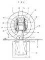
- the rotary screen textile printing machine of the present invention comprises a single or a plurality of rotary screens 1 spaced in parallel at a predetermined distance, an endless belt 2 for transporting a textile to be printed, a printing table 3 and a drive roller (not shown) for driving the endless belt 2 mounted on machine frames 4 and 5 of the textile-printing machine.
- These components 1, 2 and 3 are inclined in the width direction of the endless belt 2.
- a washing liquid sprayer 30 is disposed within the rotary screen 1.
- the washing liquid sprayer 30 is reciprocally moved at least once through the substantially entire length of the rotary screen 1 in a lengthwise direction.
- Nozzles 36 of the washing liquid sprayer 30 are oriented to the inner wall of the rotary screen 1.
- the washing liquid sprayer 30 comprises a manifold 31 mounted on a carriage 32.
- the manifold 31 has branch pipes 35, 35 that extend downwardly from the right and left ends of the manifold 31 in Fig. 2 relative to the inner surface of the rotary screen 1 . Attached at the ends of the branches 35, 35 are nozzles 36, 36, respectively.
- Preferred examples of the nozzles 36 are of the type that can change its spraying direction.
- the nozzles 36 are preferably of the wide-range spraying/blowing type that can spray washing liquid and blow compressed air over a wide range of the rotary screen.
- the carriage 32 is mounted on a bar 10 of rectangular cross section, which bar extends through the rotary screen 1 .
- the carriage 32 can slide back and forth along the bar 10 as a guide rail, but cannot rotate about the axis of the rotary screen 1 .
- the carriage 32 comprises wheels 33 that move on the bar 10 and slide shoes 34 that slide along the bar 10.
- a hose winder 40 is disposed aside of the machine frame 5.
- the hose winder 40 comprises a mount 41, a reel 42 supported thereby and a reversible geared motor 43 for rotating the reel 42. It is preferable that the motor 43 be of the variable speed type to change the later-described travel speed of the washing liquid sprayer 30, as necessary.
- Wound around the reel 42 is one end portion of the hose 38 that communicates at the other end with a liquid supply inlet 31a via a connector 37.
- the wound end of the hose 38 is connected to the wound-end-side mouth of a rotary joint 44.
- the rotary joint 44 acts as a shaft for the reel 42.
- Connected to the other end of the rotary joint 44 is a pipe 45.
- the hose 38 changes its advancing direction at an intermediate portion by a pulley 46 disposed at a position.
- the pulley 46 is supported via a pivot 47 by one end of an arm 48, the other end of which is connected to the bar 10.
- a pipe 50 Connected to the pipe 45 is one end of a pipe 50.
- the other end of the pipe 50 is connected to the connecting point between a liquid supply pipe Ia and a compressed air supply pipe IIa.
- the start end of the liquid supply pipe Ia is connected to a source I of washing liquid, for example, a pump for supplying washing liquid via a solenoid valve 51.
- the start end of the compressed air supply pipe IIa is connected to a source II of compressed air, for example, an air compressor via a solenoid valve 52.
- the pipes Ia and IIa are provided with a check valve 53, respectively.
- the hose 38 is wound up around the reel 42 by positive rotation of the reel 42, and is unwound by reverse rotation of the reel 42.
- the washing liquid sprayer 30 moves along the inclined bar 10 in the right direction of Fig. 1 because of gravity.
- the winding-up of the hose 38 makes the sprayer 30 move in the left direction of Fig. 1 .
- the washing liquid sprayer 30 reciprocally moves in the rotary screen 1, wherein the higher end of the rotary screen 1, e.g., the later-mentioned Point X is an origin or a start point of reciprocal movement, and the lower end, e.g., the later-mentioned Point Y is a turning point of reciprocal movement.
- the solenoid valve 52 In washing the rotary screen, the solenoid valve 52 is closed, and the solenoid valve 51 is opened.
- the opening and closing of these valves is controlled by an appropriate manner, for example, the following means as well as the motor 43.
- the solenoid valves 51 and 52 and the motor 43 are connected to the output side of a control circuit A.
- a control circuit A When the control circuit A is switched on, an output enters the solenoid valves 51 and 52 and the motor 43 from the control circuit A, thereby opening the solenoid valve 51, closing the solenoid valve 52 and actuating the motor 43.
- the washing liquid sprayer 30 reciprocally moves at least once through the substantially entire length of the inclined rotary screen 1.
- the reciprocal movement of the washing liquid sprayer 30 is not limited to a specific range.
- the washing liquid sprayer 30 generally moves in the range of from the left end (the flanged end) of the end ring 1R at one end (the left-side end in Fig. 1 ) of the rotary screen 1 to the intermediate portion of the end ring 1R at the other end of the rotary screen 1 .
- To describe more specifically using vertical lines through the carriage 32 it moves in the range of from Point X to Point Y as shown in Fig. 1.
- a counter is built in the control circuit A.
- the motor 43 is connected to the output side of this counter.
- the counter counts the number of rotation of the motor 43 during washing process, in other words, it counts the number of pulses transmitted from a pulse generator PG according to the amount of movement of the washing liquid sprayer 30.
- Fig. 5 is a block diagram showing the system for conducting the above-described controls.
- the rotary screen 1 and the endless belt 2 are preferably rotated.
- a roller squeegee 11 in the rotary screen 1 rotates with the rotation of the rotary screen 1, thereby contributing to the washing of the screen mesh of the rotary screen 1, and the roller squeegee 11 itself being washed.
- the printing table 3 is of the electromagnet type, more desirable effects can be obtained by exciting an electromagnet 3a.
- the roller squeegee 11 is pulled by the electromagnet 3a and pressurizedly contacts the inner surface of the rotary screen to squeezingly remove color pastes or washing liquid remaining on the rotary screen 1.
- the washing of the rotary screen 1 When the washing of the rotary screen 1 is finished, the remaining liquid on the rotary screen 1 is removed.
- the conversion of the washing mode to the liquid removal mode is controlled by an appropriate manner, for example, the following means.
- Another counter built in the control circuit A counts the number of rotation of the motor 43 during the said liquid removal process, i.e., it counts the number of pulses transmitted from the pulse generator PG according to the amount of movement of the washing liquid sprayer 30 (which is substantially a compressed air blower in the liquid removal process).
- the washing liquid sprayer 30 which is substantially a compressed air blower in the liquid removal process.
- the count of the counter has reached a predetermined number.
- an output enters the motor 43 from the control circuit A, thereby causing the motor 43 to rotate reversely.
- This control is conducted according to the program pre-stored in the control circuit A.
- Fig. 5 shows a block diagram of the control system for converting the washing mode to the liquid removal mode, as well as the control system for determining the travel range of the washing liquid sprayer 30 from Point X to Point Y.
- C1 denotes a setting device for setting the number of reciprocal movement of the washing liquid sprayer 30 during washing process
- C2 denotes a setting device for setting the number of reciprocal movement of a compressed air blower (doubled by the washing liquid sprayer 30 ) during liquid removal process.
- the preset number of reciprocal movement of the washing liquid sprayer 30 can suitably be changed according to various printing conditions such as the type or viscosity of color paste used, the shade of color, the condition of the screen mesh of the rotary screen or the like.
- a washing liquid sprayer reciprocally moves at least once through the substantially entire length of an inclined rotary screen to wash the rotary screen with the liquid sprayed from a nozzle of the sprayer. Accordingly, the rotary screen can effectively be washed over its substantially entire length with an uniform force of sprayed washing liquid, together with the fact that the nozzle of the washing liquid sprayer is oriented to the inner wall of the rotary screen. Further, every portion of the rotary screen including the end rings can be washed. If the washing liquid sprayer can stop at Point X and Y for a while, the end rings can be washed. In order to stop the washing liquid sprayer at Point X and Y for a while, an execution program is stored in the control circuit A to conduct a programed control.
- the washing liquid sprayer acts as a compressed air blower, i.e., it reciprocally moves through the substantially entire length of the rotary screen at least once to blow compressed air, whereby liquid removal can effectively be conducted on the rotary screen, even on the end rings. Further, the blowing of the compressed air contributes to preventing the nozzle from being clogged with water scale or the like. If the washing liquid sprayer stops for a while at Point X and Y, remaining liquid on the rotary screen can more effectively be removed from the end rings.
- the system for spraying washing liquid can double as the liquid removal system for blowing compressed air, whereby the usefulness of the invention would be further enhanced.
- the illustrated support structure for the rotary screen 1 is as follows.
- Bearings 6, 6 supporting the opposite ends of the rotary screen 1 are attached to a support (not shown) mounted on the frames 4 and 5 in such a manner that the right-side bearing in Fig. 1 is movable in the width direction of the textile printing machine (i.e., left and right directions of Fig. 1).
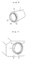
- the end rings 1R, 1R of the rotary screen 1 are detachably fitted in the bases 7, 7 that can rotate about the axes of the bearings 6, 6.
- Engaging members 71 are finned at the mouth ends of the bases 7, 7, respectively.
- engaging members 12 are finned at the mouth ends of the end rings 1R, 1R, respectively.
- the engaging members 71 and 12 are formed in plurality, as illustrated in Figs. 6 and 7.
- a sleeve-shaped support member 60 Connected to the slidable bearing 6 is a sleeve-shaped support member 60 in which a free end 61 of the bar 10, i.e., the right-side end of the bar 10 is fitted.
- the free end 61 is detachably fitted in and supported by the support member 60 .
- a bracket 8 is provided on the machine frame 5.
- the bar 10 is vertically rotatably supported via a pivot 9 at a point outside of the rotary screen 1.
- the rotary screen 1 since the rotary screen 1 has followed the rotation of the bar 10, i.e., has been raised to the said level, the rotary screen 1 can readily be withdrawn using the bar 10 as a guide or a jig.
- the lower end of the air cylinder 14 is connected to a bracket 22 via a pivot 13 on the frame 5.
- the top end of a plunger 14a is connected to the bar 10 via a pivot 16.
- the present invention can improve the washing capability of a rotary screen printing machine, reduce washing time, and lower the washing labor, thereby increasing the productivity of the printing machine.
Landscapes
- Engineering & Computer Science (AREA)
- Mechanical Engineering (AREA)
- Inking, Control Or Cleaning Of Printing Machines (AREA)
- Screen Printers (AREA)
- Treatment Of Fiber Materials (AREA)
- Coloring (AREA)
Claims (2)
- Textilrotationssiebdruckmaschine aufweisend ein Rotationssieb bzw. -raster bzw. -gitter (1), welches von seinem einen Ende zum anderen Ende geneigt ist, und ein Waschflüssigkeitszerstäuber (30), welcher im Rotationssieb (1) angeordnet ist, worin das Rotationssieb (1), Endringe bzw. -walzen (1R, 1R) aufweist, welche an seinen gegenüberliegenden bzw. entgegengesetzten Enden befestigt sind; und der Waschflüssigkeitszerstäuber (30) besitzt eine Düse (36), welche zur inneren Wand bzw. Wandung des Rotationssiebs (1) orientiert ist; und eine Vorrichtung bzw. Vorrichtungen zum reziproken bzw. gegenseitigen bzw. Hin- und Herbewegen des Waschflüssigkeitszerstäubers (30) durch bzw. entlang der im wesentlichen gesamten Länge des Rotationssiebs (1); die Vorrichtung ist betriebsbereit bzw. funktionsfähig um den Waschflüssigkeitszerstäuber (30) an einem Startpunkt und einem Wendepunkt seiner reziproken Bewegung für einen Moment bzw. eine Weile unter programmierter Kontrolle bzw. Regelung bzw. Steuerung zu stoppen, um so die Endringe (1 R, 1R) effektiv zu waschen.
- Textilrotationssiebdruckmaschine gemäß Anspruch 1, dadurch gekennzeichnet, daß der Waschflüssigkeitszerstäuber (30) eine Flüssigkeitsversorgungsröhre bzw. -rohr bzw. -leitung (50) aufweist, dessen Startende mit einer Waschflüssigkeitsquelle (I) und einer komprimierten bzw. Druckluftquelle (II) in einer wahlweise schaltbaren Weise dazwischen verbunden ist.
Applications Claiming Priority (3)
| Application Number | Priority Date | Filing Date | Title |
|---|---|---|---|
| JP9064857A JPH10250044A (ja) | 1997-03-18 | 1997-03-18 | ロータリスクリーン捺染機 |
| JP64857/97 | 1997-03-18 | ||
| JP6485797 | 1997-03-18 |
Publications (3)
| Publication Number | Publication Date |
|---|---|
| EP0865920A2 EP0865920A2 (de) | 1998-09-23 |
| EP0865920A3 EP0865920A3 (de) | 1999-03-10 |
| EP0865920B1 true EP0865920B1 (de) | 2002-01-23 |
Family
ID=13270282
Family Applications (1)
| Application Number | Title | Priority Date | Filing Date |
|---|---|---|---|
| EP98301370A Expired - Lifetime EP0865920B1 (de) | 1997-03-18 | 1998-02-25 | Textilrotationssiebdruckmaschine |
Country Status (8)
| Country | Link |
|---|---|
| EP (1) | EP0865920B1 (de) |
| JP (1) | JPH10250044A (de) |
| KR (1) | KR100257347B1 (de) |
| CN (1) | CN1093469C (de) |
| BR (1) | BR9800908A (de) |
| DE (1) | DE69803504T2 (de) |
| SG (1) | SG54622A1 (de) |
| TW (1) | TW414756B (de) |
Cited By (1)
| Publication number | Priority date | Publication date | Assignee | Title |
|---|---|---|---|---|
| CN102935762A (zh) * | 2011-08-16 | 2013-02-20 | 吴江市盛丰转移印花有限公司 | 印花机的挡片 |
Families Citing this family (6)
| Publication number | Priority date | Publication date | Assignee | Title |
|---|---|---|---|---|
| NL1011993C2 (nl) | 1999-05-07 | 2000-11-09 | Stork Brabant Bv | Zeefdrukinrichting met een in een sjabloon verplaatsbare reinigingseenheid. |
| JP4135808B2 (ja) * | 2001-07-10 | 2008-08-20 | 東海染工株式会社 | ロータリースクリーンとエンドリングの分離方法及び分離装置 |
| JP5004902B2 (ja) * | 2008-08-22 | 2012-08-22 | 株式会社椿本チエイン | 捺染機用ホース類保護案内装置 |
| CN107053826B (zh) * | 2017-04-12 | 2023-05-12 | 东莞市汇研机械有限公司 | 一种卷料平网丝网印刷方法及卷料平网丝网印刷机 |
| CN108569028A (zh) * | 2018-06-29 | 2018-09-25 | 常州宏大智能装备产业发展研究院有限公司 | 圆网印花机堵网清除方法及采用该方法的圆网印花机 |
| CN112571925B (zh) * | 2019-09-27 | 2022-04-19 | 长胜纺织科技发展(上海)有限公司 | 直驱式圆网转移印花部套装置和直驱式圆网转移印花机 |
Family Cites Families (7)
| Publication number | Priority date | Publication date | Assignee | Title |
|---|---|---|---|---|
| AT360949B (de) * | 1975-10-03 | 1981-02-10 | Zimmer Johannes | Runschablonen-waschvorrichtung |
| IT1230574B (it) * | 1988-10-20 | 1991-10-28 | Mascioni Spa | Cilindro di stampa con mezzi di lavaggio particolarmente per macchine rotative da stampa |
| NL8900868A (nl) * | 1989-04-07 | 1990-11-01 | Stork X Cel Bv | Werkwijze voor het verwijderen van dessineermateriaal van een zeefdruksjabloon, en een inrichting voor toepassing van de werkwijze. |
| IT1247795B (it) * | 1991-01-08 | 1995-01-02 | Reggiani Macchine Spa | Apparecchiatura per il lavaggio automatico delle unita' di stampa, mantenute in posizione di lavoro, utilizzate sulle macchine da stampa a cilindri rotanti |
| GB9100697D0 (en) * | 1991-01-12 | 1991-02-27 | Macfarlane & Co Ltd | Cleaning apparatus and methods of cleaning |
| EP0641649A1 (de) * | 1993-09-04 | 1995-03-08 | Kissel & Wolf GmbH | Verfahren zum Entfernen der Schablonenbeschichtung auf Siebdruckformen sowie Vorrichtung zur Durchführung dieses Verfahrens |
| JPH08276564A (ja) * | 1994-11-09 | 1996-10-22 | Ichinose Internatl:Kk | 自動ロータリスクリーン捺染機及びそれのスクリーン洗浄方法 |
-
1997
- 1997-03-18 JP JP9064857A patent/JPH10250044A/ja active Pending
-
1998
- 1998-02-18 TW TW087102290A patent/TW414756B/zh not_active IP Right Cessation
- 1998-02-25 EP EP98301370A patent/EP0865920B1/de not_active Expired - Lifetime
- 1998-02-25 DE DE69803504T patent/DE69803504T2/de not_active Expired - Fee Related
- 1998-02-26 SG SG1998000441A patent/SG54622A1/en unknown
- 1998-03-04 KR KR1019980007017A patent/KR100257347B1/ko not_active Expired - Fee Related
- 1998-03-16 CN CN98101013A patent/CN1093469C/zh not_active Expired - Lifetime
- 1998-03-16 BR BR9800908-7A patent/BR9800908A/pt not_active IP Right Cessation
Cited By (1)
| Publication number | Priority date | Publication date | Assignee | Title |
|---|---|---|---|---|
| CN102935762A (zh) * | 2011-08-16 | 2013-02-20 | 吴江市盛丰转移印花有限公司 | 印花机的挡片 |
Also Published As
| Publication number | Publication date |
|---|---|
| CN1093469C (zh) | 2002-10-30 |
| CN1193569A (zh) | 1998-09-23 |
| JPH10250044A (ja) | 1998-09-22 |
| DE69803504T2 (de) | 2002-10-24 |
| BR9800908A (pt) | 1999-09-14 |
| KR100257347B1 (ko) | 2000-05-15 |
| DE69803504D1 (de) | 2002-03-14 |
| EP0865920A2 (de) | 1998-09-23 |
| KR19980079858A (ko) | 1998-11-25 |
| SG54622A1 (en) | 1998-11-16 |
| EP0865920A3 (de) | 1999-03-10 |
| TW414756B (en) | 2000-12-11 |
Similar Documents
| Publication | Publication Date | Title |
|---|---|---|
| JPH04153357A (ja) | 連続スプレー染色の色替装置 | |
| KR900003671B1 (ko) | 윤전인쇄기의 가이드로울러 세정방법 및 장치 | |
| US5437723A (en) | Coating machine for the processing of chocolate and similar masses | |
| DE4310546A1 (de) | Verfahren und Vorrichtung zum Waschen eines Förderbandes in einem Wärmebehandlungsgerät | |
| US8336564B2 (en) | Method and apparatus for cleaning a coating machine | |
| EP0865920A2 (de) | Textilrotationssiebdruckmaschine | |
| JP2000511835A (ja) | フレキソ印刷プレートを清掃するための方法と装置 | |
| EP0353751B1 (de) | Reinigungsanlage für Waagen, insbesondere Kombinationswaagen | |
| CN112238029A (zh) | 一种涂布装置 | |
| JPH07241977A (ja) | スクリーン印刷機 | |
| US4622246A (en) | Method of polishing a vehicle | |
| US4335593A (en) | Chainless mercerizing equipment using a dye padder | |
| EP1260628B1 (de) | Vorrichtung und Verfahren zur Nassbehandlung einer strangförmigen Warenbahn | |
| CN117261439A (zh) | 一种自清洁喷码机 | |
| EP0502240B1 (de) | Verfahren und Vorrichtung zum Waschen und Wechseln von Siebdruckrahmen in eine automatische Siebdruckmaschine | |
| CN208235118U (zh) | 一种全自动面料改色设备 | |
| JPH06136609A (ja) | 糸条移送ロールの洗浄装置およびその洗浄方法 | |
| JPH06184807A (ja) | 糸条移送ロールの洗浄装置およびその洗浄方法 | |
| JPS6250144A (ja) | 印刷機におけるインキ洗浄液の自動噴射装置 | |
| CN1443890A (zh) | 用于对纺织原料进行染色的料桶和方法 | |
| EP1162299B1 (de) | Maschine zur Behandlung, insbesondere zum Färben von strangförmigen Geweben | |
| US5762649A (en) | Storage apparatus for round stencils | |
| KR100548892B1 (ko) | 날염 스크린 세척 장치 | |
| JPS6221901B2 (de) | ||
| JPH0557910B2 (de) |
Legal Events
| Date | Code | Title | Description |
|---|---|---|---|
| PUAI | Public reference made under article 153(3) epc to a published international application that has entered the european phase |
Free format text: ORIGINAL CODE: 0009012 |
|
| AK | Designated contracting states |
Kind code of ref document: A2 Designated state(s): CH DE FR GB IT LI NL |
|
| AX | Request for extension of the european patent |
Free format text: AL;LT;LV;MK;RO;SI |
|
| PUAL | Search report despatched |
Free format text: ORIGINAL CODE: 0009013 |
|
| AK | Designated contracting states |
Kind code of ref document: A3 Designated state(s): AT BE CH DE DK ES FI FR GB GR IE IT LI LU MC NL PT SE |
|
| AX | Request for extension of the european patent |
Free format text: AL;LT;LV;MK;RO;SI |
|
| 17P | Request for examination filed |
Effective date: 19990903 |
|
| AKX | Designation fees paid |
Free format text: CH DE FR GB IT LI NL |
|
| 17Q | First examination report despatched |
Effective date: 20000221 |
|
| GRAG | Despatch of communication of intention to grant |
Free format text: ORIGINAL CODE: EPIDOS AGRA |
|
| GRAG | Despatch of communication of intention to grant |
Free format text: ORIGINAL CODE: EPIDOS AGRA |
|
| GRAH | Despatch of communication of intention to grant a patent |
Free format text: ORIGINAL CODE: EPIDOS IGRA |
|
| GRAH | Despatch of communication of intention to grant a patent |
Free format text: ORIGINAL CODE: EPIDOS IGRA |
|
| GRAA | (expected) grant |
Free format text: ORIGINAL CODE: 0009210 |
|
| REG | Reference to a national code |
Ref country code: GB Ref legal event code: IF02 |
|
| AK | Designated contracting states |
Kind code of ref document: B1 Designated state(s): CH DE FR GB IT LI NL |
|
| REG | Reference to a national code |
Ref country code: CH Ref legal event code: EP |
|
| REF | Corresponds to: |
Ref document number: 69803504 Country of ref document: DE Date of ref document: 20020314 |
|
| REG | Reference to a national code |
Ref country code: CH Ref legal event code: NV Representative=s name: RITSCHER & PARTNER AG PATENTANWAELTE |
|
| ET | Fr: translation filed | ||
| PLBE | No opposition filed within time limit |
Free format text: ORIGINAL CODE: 0009261 |
|
| STAA | Information on the status of an ep patent application or granted ep patent |
Free format text: STATUS: NO OPPOSITION FILED WITHIN TIME LIMIT |
|
| 26N | No opposition filed | ||
| REG | Reference to a national code |
Ref country code: CH Ref legal event code: NV Representative=s name: SERVOPATENT GMBH |
|
| PGFP | Annual fee paid to national office [announced via postgrant information from national office to epo] |
Ref country code: CH Payment date: 20060208 Year of fee payment: 9 |
|
| PGFP | Annual fee paid to national office [announced via postgrant information from national office to epo] |
Ref country code: DE Payment date: 20060224 Year of fee payment: 9 |
|
| PGFP | Annual fee paid to national office [announced via postgrant information from national office to epo] |
Ref country code: FR Payment date: 20060227 Year of fee payment: 9 |
|
| PGFP | Annual fee paid to national office [announced via postgrant information from national office to epo] |
Ref country code: NL Payment date: 20070131 Year of fee payment: 10 |
|
| PG25 | Lapsed in a contracting state [announced via postgrant information from national office to epo] |
Ref country code: LI Free format text: LAPSE BECAUSE OF NON-PAYMENT OF DUE FEES Effective date: 20070228 Ref country code: CH Free format text: LAPSE BECAUSE OF NON-PAYMENT OF DUE FEES Effective date: 20070228 |
|
| REG | Reference to a national code |
Ref country code: CH Ref legal event code: PL |
|
| GBPC | Gb: european patent ceased through non-payment of renewal fee |
Effective date: 20070225 |
|
| REG | Reference to a national code |
Ref country code: FR Ref legal event code: ST Effective date: 20071030 |
|
| PGFP | Annual fee paid to national office [announced via postgrant information from national office to epo] |
Ref country code: IT Payment date: 20070509 Year of fee payment: 10 |
|
| PG25 | Lapsed in a contracting state [announced via postgrant information from national office to epo] |
Ref country code: DE Free format text: LAPSE BECAUSE OF NON-PAYMENT OF DUE FEES Effective date: 20070901 |
|
| PG25 | Lapsed in a contracting state [announced via postgrant information from national office to epo] |
Ref country code: GB Free format text: LAPSE BECAUSE OF NON-PAYMENT OF DUE FEES Effective date: 20070225 Ref country code: FR Free format text: LAPSE BECAUSE OF NON-PAYMENT OF DUE FEES Effective date: 20070228 |
|
| PGFP | Annual fee paid to national office [announced via postgrant information from national office to epo] |
Ref country code: GB Payment date: 20060126 Year of fee payment: 9 |
|
| NLV4 | Nl: lapsed or anulled due to non-payment of the annual fee |
Effective date: 20080901 |
|
| PG25 | Lapsed in a contracting state [announced via postgrant information from national office to epo] |
Ref country code: NL Free format text: LAPSE BECAUSE OF NON-PAYMENT OF DUE FEES Effective date: 20080901 |
|
| PG25 | Lapsed in a contracting state [announced via postgrant information from national office to epo] |
Ref country code: IT Free format text: LAPSE BECAUSE OF NON-PAYMENT OF DUE FEES Effective date: 20080225 |