EP0865922A2 - Tintenstrahldruckkopfdüse zur Sprühreduzierung - Google Patents
Tintenstrahldruckkopfdüse zur Sprühreduzierung Download PDFInfo
- Publication number
- EP0865922A2 EP0865922A2 EP98300438A EP98300438A EP0865922A2 EP 0865922 A2 EP0865922 A2 EP 0865922A2 EP 98300438 A EP98300438 A EP 98300438A EP 98300438 A EP98300438 A EP 98300438A EP 0865922 A2 EP0865922 A2 EP 0865922A2
- Authority
- EP
- European Patent Office
- Prior art keywords
- orifice
- ink
- aperture
- dimension
- shape
- Prior art date
- Legal status (The legal status is an assumption and is not a legal conclusion. Google has not performed a legal analysis and makes no representation as to the accuracy of the status listed.)
- Granted
Links
Images





Classifications
-
- B—PERFORMING OPERATIONS; TRANSPORTING
- B41—PRINTING; LINING MACHINES; TYPEWRITERS; STAMPS
- B41J—TYPEWRITERS; SELECTIVE PRINTING MECHANISMS, i.e. MECHANISMS PRINTING OTHERWISE THAN FROM A FORME; CORRECTION OF TYPOGRAPHICAL ERRORS
- B41J2/00—Typewriters or selective printing mechanisms characterised by the printing or marking process for which they are designed
- B41J2/005—Typewriters or selective printing mechanisms characterised by the printing or marking process for which they are designed characterised by bringing liquid or particles selectively into contact with a printing material
- B41J2/01—Ink jet
- B41J2/135—Nozzles
- B41J2/14—Structure thereof only for on-demand ink jet heads
-
- B—PERFORMING OPERATIONS; TRANSPORTING
- B41—PRINTING; LINING MACHINES; TYPEWRITERS; STAMPS
- B41J—TYPEWRITERS; SELECTIVE PRINTING MECHANISMS, i.e. MECHANISMS PRINTING OTHERWISE THAN FROM A FORME; CORRECTION OF TYPOGRAPHICAL ERRORS
- B41J2/00—Typewriters or selective printing mechanisms characterised by the printing or marking process for which they are designed
- B41J2/005—Typewriters or selective printing mechanisms characterised by the printing or marking process for which they are designed characterised by bringing liquid or particles selectively into contact with a printing material
- B41J2/01—Ink jet
- B41J2/135—Nozzles
- B41J2/14—Structure thereof only for on-demand ink jet heads
- B41J2/14016—Structure of bubble jet print heads
-
- B—PERFORMING OPERATIONS; TRANSPORTING
- B41—PRINTING; LINING MACHINES; TYPEWRITERS; STAMPS
- B41J—TYPEWRITERS; SELECTIVE PRINTING MECHANISMS, i.e. MECHANISMS PRINTING OTHERWISE THAN FROM A FORME; CORRECTION OF TYPOGRAPHICAL ERRORS
- B41J2/00—Typewriters or selective printing mechanisms characterised by the printing or marking process for which they are designed
- B41J2/005—Typewriters or selective printing mechanisms characterised by the printing or marking process for which they are designed characterised by bringing liquid or particles selectively into contact with a printing material
- B41J2/01—Ink jet
- B41J2/135—Nozzles
- B41J2/14—Structure thereof only for on-demand ink jet heads
- B41J2/1433—Structure of nozzle plates
-
- B—PERFORMING OPERATIONS; TRANSPORTING
- B41—PRINTING; LINING MACHINES; TYPEWRITERS; STAMPS
- B41J—TYPEWRITERS; SELECTIVE PRINTING MECHANISMS, i.e. MECHANISMS PRINTING OTHERWISE THAN FROM A FORME; CORRECTION OF TYPOGRAPHICAL ERRORS
- B41J2/00—Typewriters or selective printing mechanisms characterised by the printing or marking process for which they are designed
- B41J2/005—Typewriters or selective printing mechanisms characterised by the printing or marking process for which they are designed characterised by bringing liquid or particles selectively into contact with a printing material
- B41J2/01—Ink jet
- B41J2/135—Nozzles
- B41J2/16—Production of nozzles
- B41J2/1601—Production of bubble jet print heads
- B41J2/1603—Production of bubble jet print heads of the front shooter type
-
- B—PERFORMING OPERATIONS; TRANSPORTING
- B41—PRINTING; LINING MACHINES; TYPEWRITERS; STAMPS
- B41J—TYPEWRITERS; SELECTIVE PRINTING MECHANISMS, i.e. MECHANISMS PRINTING OTHERWISE THAN FROM A FORME; CORRECTION OF TYPOGRAPHICAL ERRORS
- B41J2/00—Typewriters or selective printing mechanisms characterised by the printing or marking process for which they are designed
- B41J2/005—Typewriters or selective printing mechanisms characterised by the printing or marking process for which they are designed characterised by bringing liquid or particles selectively into contact with a printing material
- B41J2/01—Ink jet
- B41J2/135—Nozzles
- B41J2/16—Production of nozzles
- B41J2/162—Manufacturing of the nozzle plates
-
- B—PERFORMING OPERATIONS; TRANSPORTING
- B41—PRINTING; LINING MACHINES; TYPEWRITERS; STAMPS
- B41J—TYPEWRITERS; SELECTIVE PRINTING MECHANISMS, i.e. MECHANISMS PRINTING OTHERWISE THAN FROM A FORME; CORRECTION OF TYPOGRAPHICAL ERRORS
- B41J2/00—Typewriters or selective printing mechanisms characterised by the printing or marking process for which they are designed
- B41J2/005—Typewriters or selective printing mechanisms characterised by the printing or marking process for which they are designed characterised by bringing liquid or particles selectively into contact with a printing material
- B41J2/01—Ink jet
- B41J2/135—Nozzles
- B41J2/16—Production of nozzles
- B41J2/1621—Manufacturing processes
- B41J2/1625—Manufacturing processes electroforming
-
- B—PERFORMING OPERATIONS; TRANSPORTING
- B41—PRINTING; LINING MACHINES; TYPEWRITERS; STAMPS
- B41J—TYPEWRITERS; SELECTIVE PRINTING MECHANISMS, i.e. MECHANISMS PRINTING OTHERWISE THAN FROM A FORME; CORRECTION OF TYPOGRAPHICAL ERRORS
- B41J2/00—Typewriters or selective printing mechanisms characterised by the printing or marking process for which they are designed
- B41J2/005—Typewriters or selective printing mechanisms characterised by the printing or marking process for which they are designed characterised by bringing liquid or particles selectively into contact with a printing material
- B41J2/01—Ink jet
- B41J2/135—Nozzles
- B41J2/14—Structure thereof only for on-demand ink jet heads
- B41J2002/14475—Structure thereof only for on-demand ink jet heads characterised by nozzle shapes or number of orifices per chamber
-
- B—PERFORMING OPERATIONS; TRANSPORTING
- B41—PRINTING; LINING MACHINES; TYPEWRITERS; STAMPS
- B41J—TYPEWRITERS; SELECTIVE PRINTING MECHANISMS, i.e. MECHANISMS PRINTING OTHERWISE THAN FROM A FORME; CORRECTION OF TYPOGRAPHICAL ERRORS
- B41J2202/00—Embodiments of or processes related to ink-jet or thermal heads
- B41J2202/01—Embodiments of or processes related to ink-jet heads
- B41J2202/11—Embodiments of or processes related to ink-jet heads characterised by specific geometrical characteristics
Definitions
- the present invention is generally related to an inkjet printer printhead having an improved orifice design and is more particularly related to a printhead orifice design having an opening with characteristics producing reduced ink spray.
- An inkjet printer forms characters and images on a medium, such as paper, by expelling droplets of ink in a controlled fashion so that the droplets land in desired locations on the medium.
- a printer can be conceptualized as a mechanism for moving and placing the medium in a position such that the ink droplets can be placed on the medium, a printing cartridge which controls the flow of ink and expels droplets of ink to the medium, and appropriate control hardware and software.
- a conventional print cartridge for an inkjet printer comprises an ink containment section, which stores and supplies ink as needed, and a printhead, which heats and expels the ink droplets as directed by the printer control software.
- the printhead is a laminate structure including a semiconductor base, a barrier material structure which is honeycombed with ink flow channels, and an orifice plate which is perforated with small holes or orifices arranged in a pattern which allows ink droplets to be expelled.
- the expulsion mechanism consists of a plurality of heater resistors formed in the semiconductor substrate which are each associated with one of a plurality of ink firing chambers formed in the barrier layer and one orifice of a plurality of orifi in the orifice plate.
- Each of the heater resistors is connected to the controlling software of the printer such that each of the resistors may be independently energized to quickly vaporize a portion of ink into a bubble which subsequently expels a droplet of ink from an orifice.
- Ink flows into the firing chamber formed in the barrier layer around each heater resistor and awaits energization of the heater resistor.
- ink refills the firing chamber to the point where a meniscus is formed across the orifice.
- the form and constrictions in barrier layer channels through which ink flows to refill the firing chamber establish both the speed at which ink refills the firing chamber and the dynamics of the ink meniscus.
- Some of the ink in the severed tail rejoins the expelled droplet or remains as a distortion of the droplet to create rough edges on the printed material. Some of the expelled ink in the tail returns to the printhead, forming puddles on the surface of the orifice plate of the printhead. Some of the ink in the severed tail forms subdroplets ("spray") which travel and spread randomly in the general direction of the ink droplet. This spray often lands on the medium to produce a background of ink haze.
- subdroplets subdroplets
- FIG. 1 which is not drawn to scale
- a substrate 101 has at least one flat surface constructed of silicon or glass.
- a conducting layer 103 Disposed on the flat surface of the substrate 101 is a conducting layer 103, generally a film of chromium or stainless steel.
- a vacuum deposition process such as the planar magnetron process, may be used to deposit this conductive film 103.
- Another vacuum deposition process may be used to deposit a dielectric layer 105, which typically is silicon nitride, and is deposed by a vacuum deposition process such as a plasma enhanced chemical vapor deposition process.
- Dielectric layer 105 is desirably very thin, typically having a thickness of approximately 0.30 ⁇ m.
- Dielectric layer 105 is masked with a photoresist mask, exposed to UV light, and introduced into a plasma etching process which removes most of the dielectric layer except for "buttons" of dielectric material in preselected positions on the conductive layer 103. Of course, these positions are predetermined to be the location of each orifice of the orifice plate which is to be created atop the mandrel.
- This reusable mandrel is placed into an electroforming bath in which the conducting layer 103 is established as a cathode while a base material, typically nickel, is established as the anode.
- a base material typically nickel
- nickel metal is transferred from the anode to the cathode and the nickel (shown as layer 107) attaches to the conductive areas of the conductive layer 103. Since the nickel metal plates uniformly from each conductive plate of the mandrel, once the surface of the dielectric button 105 is reached, the nickel overplates the dielectric layer in a uniform and predictable pattern.
- the parameters of the plating process are carefully controlled so that the opening of the nickel layer 107 formed over the dielectric layer button 105 is a predetermined diameter (typically about 45 ⁇ m) at the dielectric surface. This diameter is usually one third to one fifth the diameter of the dielectric layer button 105 thereby resulting in the top layer of the nickel 107 having an opening at the inner surface of the orifice plate of diameter d2 which is approximately three to five times the diameter of d1 of the opening which will be the orifice aperture at the external surface of the orifice plate.
- the newly formed orifice plate is removed from the mandrel and gold plated for corrosion resistance of the orifice. Additional description of metal orifice plate fabrication may be found in US Patent Nos. 4,773,971; 5,167,776; 5,443,713; and 5,560,837, each assigned to the assignee of the present invention.
- the present invention encompasses a printhead for an inkjet printer which utilizes an ink ejector to expel ink from orifi in an orifice plate.
- the orifice plate has at least one orifice extending through the orifice plate from a first surface of the orifice plate opposite the ink ejector to a second surface of the orifice plate essentially parallel the first surface.
- the orifice includes an aperture at the second surface with a first lineal dimension parallel to the second surface and a second lineal dimension parallel to the second surface and perpendicular to the first lineal dimension. Further, the first lineal dimension has a greater magnitude than the second lineal dimension.
- the aperture of the orifice at the second surface is defined by at least two non-intersecting edges of the second surface which are spaced apart at one point by a distance of the second dimension and spaced apart at all other points by a distance greater than the second dimension.
- FIG. 1 is a cross section of an orifice plate forming mandrel and an orifice plate formed on the mandrel.
- FIG. 2 is a cross sectional view of a conventional printhead showing one ink firing chamber.
- FIG. 3 is a plan view of the outer surface of the orifice plate of a conventional printhead.
- FIG. 4 is a cross sectional view of a conventional printhead illustrating the expulsion of an ink droplet.
- FIG. 5 is a theoretical model of the droplet-meniscus system which may be useful in understanding the performance of the present invention.
- FIG. 6 is a reproduction of the detrimental effects of spray and elongated droplet tail upon a printed medium.
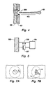
- FIGs. 7A and 7B are plan views from the external surface of the orifice plate showing orifice surface apertures.
- FIG. 8 is a plan view from the external surface of the orifice plate showing an orifice surface aperture which may be employed in the present invention.
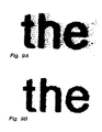
- FIGs. 9A and 9B are reproductions of spray effects upon a printed medium and the improvement offered by the present invention.
- FIG. 10 illustrates a technique of forming an orifice aperture which may be employed in the present invention.
- FIG. 11 illustrates a technique of forming an orifice aperture which may be employed in the present invention.
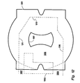
- FIG. 12 is a plan view from the external surface of the orifice plate illustrating the orifice surface aperture and orifice bore in relation to an ink firing chamber, as may be employed in the present invention.
- FIG. 2 A cross section of a conventional printhead is shown in FIG. 2.
- a thin film resistor 201 is created at the surface of a semiconductor substrate 203 and typically is connected to electrical inputs by way of a metalization (not shown) on the surface of the semiconductor substrate 203. Additionally, various layers offering protection from chemical and mechanical attack may be placed over the heater resistor 201, but are not shown in FIG. 2 for clarity.
- a layer of barrier material 205 is selectively placed on the surface of the silicon substrate 203 (or less thereon) thereby leaving an opening or ink firing chamber 207 around the heater resistor 201 so that ink may accumulate in the firing chamber prior to activation of heater resistor 201 and ejection of ink through an orifice 209.
- the barrier material for barrier layer 205 is conventionally Parad® available from E.I. DuPont De Nemours and Company or equivalent material.
- the orifice 209 is a hole in the orifice plate 107 extending from the inside surface of the orifice plate to the external surface of the orifice plate and which can be formed as part of the orifice plate as previously described.
- FIG. 3 is a top plan view of a conventional printhead (indicating the section A-A of FIG. 2), viewing orifice 209 from the external surface 213 of the orifice plate 107.
- An ink feed channel 301 is present in the barrier layer 205 to deliver ink to the ink firing chamber from a larger ink source (not shown).
- FIG. 4 illustrates the configuration of ink in an ink droplet 401 at a time 22 microseconds after the ink has been expelled from the orifice 209.
- the ink droplet 401 maintains a long tail 403 which can be seen to extend back to at least the orifice 209 in the orifice plate 107.
- Printhead designers have improved and optimized the damping of the ink refill and meniscus system by increasing the fluid resistance of the ink refill channel. Typically this improvement has been accomplished by lengthening the ink refill channel, decreasing the ink refill channel cross section, or by increasing the viscosity of the ink. Such an increase in ink refill fluid resistance often results in slower refill times and a reduced rate of droplet ejection and printing speed.
- a simplified analysis of the meniscus system is one such as the mechanical model shown in FIG. 5, in which a mass 501, equivalent to the mass of the expelled droplet, is coupled to a fixed structure 503 by a spring 505 having a spring constant, K, proportional to the reciprocal of the effective radius of the orifice.
- the mass 501 is also coupled to the fixed structure 503 by a damping function 507 which is related to the channel fluid resistance and other ink channel characteristics.
- the drop weight mass 501 is proportional to the diameter of the orifice.
- the droplet 401 When the droplet 401 is ejected from the orifice most of the mass of the droplet is contained in the leading head of the droplet 401 and the greatest velocity is found in this mass.
- the remaining tail 403 contains a minority of the mass of ink and has a distribution of velocity ranging from nearly the same as the ink droplet head at a location near the ink droplet head to a velocity less than the velocity of the ink found in the ink droplet head and located closest to the orifice aperture.
- the ink in the tail At some time during the transit of the droplet, the ink in the tail is stretched to a point where the tail is broken off from the droplet.
- a portion of the ink remaining in the tail is pulled back to the printhead orifice plate 107 where it typically forms puddles of ink surrounding the orifice. These ink puddles degrade the quality of the printed material by causing misdirection of subsequent ink droplets.
- Other parts of the ink droplet tail are absorbed into the ink droplet head prior to the ink droplet being deposited upon the medium.
- some of the ink found in the ink droplet tail neither returns to the printhead nor remains with or is absorbed in the ink droplet, but produces a fine spray of subdroplets spreading in a random direction.
- the exit area of the orifice aperture 209 to the external environment defines the drop weight of the ink droplet expelled. It has further been determined that the restoring force of the meniscus (constant K in the model) is determined in part by the proximity of the edges of the orifice aperture. Thus, to increase the stiffness of the meniscus, the sides and opening of the orifice bore hole should be made as close together as possible. This, of course, is in contradiction to the need to maintain a given drop weight for the droplet (which is determined by the exit area of the orifice). A greater restoring force on the meniscus provided by the non-circular geometry causes the tail of the ink droplet to be broken off sooner and closer to the orifice plate thereby resulting in a shorter ink droplet tail and significantly reduced spray.
- Some non-circular orifices which may be utilized to reduce spray are elongated apertures having a major axis and a minor axis, in which the major axis is of a greater dimension than the minor axis and both axes are parallel to the outer surface of the orifice plate.
- Such elongate structures can be rectangles and parallelograms or ovals such as ellipses and parallel-sided "racetrack" structures.
- FIGS. 7A-7B are plan views of the orifice plate external surface illustrating the various types of orifice bore hole dimensions.
- FIG. 7A illustrates a circular orifice having a radius r at the outer dimension and a difference in radius between the outer dimension r and the opening to the firing chamber of value r 2 .
- r 17.5 micron
- r 2 45 microns. This yields an aperture area at the orifice plate outer surface (r 2 • ⁇ ) of 962 microns 2 .
- FIG. 7B illustrates an ellipsoidal external orifice aperture geometry in which the major axis/minor axis ratio equals 2 to 1 and, in order to maintain an equal droplet drop weight, the outer area of the orifice opening is maintained at 962 microns 2 .
- the major and minor axes (a, b) of the ellipse are respectively 28.5 microns and 12.4 microns for the 2:1 ellipse.
- the major contributing factor to the better tail break-off and subsequent spray reduction is the reduction of the size of the minor axis of the ellipse. Within the range of axis ratios of 2:1 to approximately 5:1, reduction of spray is observed.
- One drawback, which was also noted above, is that elliptic orifi surface openings have a corresponding larger opening at the interior surface of the orifice plate (at the ink firing chamber). These interior openings will overlap and interfere when the orifi are spaced closely together for improved print resolution. This interference takes the form of ink from one firing chamber being blown into an adjacent firing chamber and other subtle but detrimental effects.
- the ellipse has been distorted in the major axis direction, to create, in essence, a crescent or quarter moon shape.
- the minor axis dimension is preserved and the effective major axis is shortened with this crescent shape while the overall orifice aperture area remains constant.
- Appropriate spray reduction continues to be achieved using a crescent orifice opening shape.
- the crescent shape introduces a different problem into the quality of print realized with this form of printhead.
- the trajectory of the ink droplets leaving the orifice plate is not perpendicular to the orifice plate surface but is tilted away from perpendicularity toward the direction of the negative radius of curvature surface of the orifice aperture.
- FIG. 8 Another shape which provides symmetry is created by overlaying two crescent shapes with the limbs of the crescent facing away from each other. Such a shape is illustrated in FIG. 8.
- This modified orifice aperture shape has been deemed a "hourglass" shape.
- the modified minor axis (b H ) has been set at 26 ⁇ m while the modified major axis (a H ) has been established at 69 ⁇ m.
- the edges which define the modified minor axis have a radius of curvature (r H ) of approximately 47 ⁇ m.
- This unique orifice aperture shape preserves the narrow minor axis opening while reducing the necessary major axis dimension required for the fixed orifice aperture area.
- the reduced dimension major axis allows closer spacing of the orifi than could otherwise be realized with an ellipse of the same orifice aperture area.
- the hourglass orifice aperture shape provides a symmetry about both major and minor axes and overcomes the problem of trajectory error of an ink droplet.
- the improvement afforded by the hourglass shaped orifice aperture over a conventional circular opening can be appreciated by comparing FIG. 9B with FIG. 9A.
- the highly magnified letters of FIG. 9B show very few of the extraneous droplets which are seen in the print of FIG. 9A.
- the orifice plate is conventionally formed by electroplating nickel or similar metal on a mandrel and then plating the orifice plate with chemically resistant materials such as gold.
- a non-conductive button in the shape of the desired end result: the circular orifice aperture.
- FIG. 1 in which the base metal 107 grows over the top surface of the non-conducting insulating button 105.
- a detail in the outline of the button 107 can be obscured or transformed into other shapes as the base metal 107 grows over the insulating button 105 top surface.
- the hourglass shape of the orifice aperture is identified as 1001.
- a family of circles having a radius equal to the desired growth of base metal is represented by circle 1003.
- the outline of the non-conductive button is shown as 1005.
- Each circle of the family of circles is made tangent to the hourglass orifice shape at a point along the edge of the hourglass shape. Taking the point directly across the diameter of each circle and joining those points yields the shape of the non-conducting button.
- the shape of the non-conducting button does not have to be identical to the shape of the orifice. Observe that at the limbs of the hourglass shape 1001, the number of circles needed to define the shape diminishes.
- FIG. 11 illustrates the necessary construction circles needed to create the orifice opening 1001. Joining the points on the circumference opposite the point of tangency yields the minimum button outline needed to produce the hourglass orifice opening desired.
- These outline configurations include arc 1101 and arc 1103 to produce the edges forming the terminals of the major axis and parabolic portions 1105 and 1107 to produce the edges forming the terminals of the minor axes.
- the hourglass orifice shape produced by electroplating an orifice plate will be independent of the button outline other than the identified arcs and parabolic sections.
- FIG. 12 illustrates the printhead which is obtained when the non-conducting mandrel button shape is partially independent of the orifice surface hole shape.
- the orifice aperture 1001 and the button shape 1201 are shown in solid line for the sake of clarity although the orifice hole 1101 is located on the external surface of the orifice plate and the button shape is located on the inner surface of the orifice plate.
- the bore of the orifice changes from the button shape 1201 to the hourglass shaped aperture 1001 as one views the orifice bore starting at the ink firing chamber and traverses to the opening at the surface of the orifice plate.
- the configuration of the barrier layer material is shown in broken line.
- An island of barrier material 1203 divides the ink inlet to the firing chamber 1205 into two ink channels 1207 and 1209 and the remainder of the firing chamber 1205 is defined by walls of barrier material 1211, 1213, 1215, etc. Improved areas of contact between the barrier layer material and the orifice plate are realized in the zone around the barrier island 1203 (and illustrated with further broken line representing the hypothetical circular button outline).
- This improved contact area is a result of the squaring of the button shape in portions which would otherwise be circular to better match the square implementation of the barrier material and provides a rectangular cross section at the substrate which does not vary even when a misalignment of the orifice plate occurs. Further, the square implementation provides increased ink volume in the firing chamber. Thus, the present invention allows a closer spacing of orifi with reduced spray and improved ink droplet trajectory.
Landscapes
- Engineering & Computer Science (AREA)
- Manufacturing & Machinery (AREA)
- Particle Formation And Scattering Control In Inkjet Printers (AREA)
- Ink Jet (AREA)
- Pens And Brushes (AREA)
Applications Claiming Priority (2)
| Application Number | Priority Date | Filing Date | Title |
|---|---|---|---|
| US805488 | 1997-02-25 | ||
| US08/805,488 US6123413A (en) | 1995-10-25 | 1997-02-25 | Reduced spray inkjet printhead orifice |
Publications (3)
| Publication Number | Publication Date |
|---|---|
| EP0865922A2 true EP0865922A2 (de) | 1998-09-23 |
| EP0865922A3 EP0865922A3 (de) | 1999-06-16 |
| EP0865922B1 EP0865922B1 (de) | 2003-05-14 |
Family
ID=25191697
Family Applications (1)
| Application Number | Title | Priority Date | Filing Date |
|---|---|---|---|
| EP98300438A Expired - Lifetime EP0865922B1 (de) | 1997-02-25 | 1998-01-22 | Tintenstrahldruckkopfdüse zur Sprühreduzierung |
Country Status (7)
| Country | Link |
|---|---|
| US (1) | US6123413A (de) |
| EP (1) | EP0865922B1 (de) |
| JP (2) | JP3982892B2 (de) |
| KR (1) | KR100439392B1 (de) |
| CN (1) | CN1092571C (de) |
| DE (1) | DE69814503T2 (de) |
| TW (1) | TW345543B (de) |
Cited By (30)
| Publication number | Priority date | Publication date | Assignee | Title |
|---|---|---|---|---|
| EP1121249A4 (de) * | 1998-10-16 | 2002-07-03 | Silverbrook Res Pty Ltd | Verbesserungen an tintenstrahldruckern |
| US6913347B2 (en) | 1998-10-16 | 2005-07-05 | Silverbrook Research Pty Ltd | Inkjet printhead chip with trace orientation to enhance performance characteristics |
| US6938994B2 (en) | 1998-10-16 | 2005-09-06 | Silverbrook Research Pty Ltd | Method of operating an ink jet printhead within a predetermined temperature range |
| US6994424B2 (en) | 1998-10-16 | 2006-02-07 | Silverbrook Research Pty Ltd | Printhead assembly incorporating an array of printhead chips on an ink distribution structure |
| US7014785B2 (en) | 1998-09-09 | 2006-03-21 | Silverbrook Research Pty Ltd | Method of fabricating inkjet nozzle |
| US7032992B2 (en) | 1998-10-16 | 2006-04-25 | Silverbrook Research Pty Ltd | Inkjet printer using meniscus rim in nozzle chamber |
| US7080893B2 (en) | 1998-10-16 | 2006-07-25 | Silverbrook Research Pty Ltd | Ink jet printhead having columnar arrays of transistor drive circuits |
| US7111924B2 (en) | 1998-10-16 | 2006-09-26 | Silverbrook Research Pty Ltd | Inkjet printhead having thermal bend actuator heating element electrically isolated from nozzle chamber ink |
| US7175775B2 (en) | 1998-10-16 | 2007-02-13 | Silverbrook Research Pty Ltd | Method of fabricating printhead IC using CTE matched wafer and sacrificial materials |
| US7182431B2 (en) | 1999-10-19 | 2007-02-27 | Silverbrook Research Pty Ltd | Nozzle arrangement |
| US7216956B2 (en) | 1998-10-16 | 2007-05-15 | Silverbrook Research Pty Ltd | Printhead assembly with power and ground connections along single edge |
| US7237874B2 (en) | 2000-06-30 | 2007-07-03 | Silverbrook Research Pty Ltd | Inkjet printhead with grouped nozzles and a nozzle guard |
| US7360463B2 (en) | 2002-01-24 | 2008-04-22 | Sensarray Corporation | Process condition sensing wafer and data analysis system |
| US7380906B2 (en) | 1998-10-16 | 2008-06-03 | Silverbrook Research Pty Ltd | Printhead |
| US7384131B2 (en) | 1998-10-16 | 2008-06-10 | Silverbrook Research Pty Ltd | Pagewidth printhead having small print zone |
| US7419250B2 (en) | 1999-10-15 | 2008-09-02 | Silverbrook Research Pty Ltd | Micro-electromechanical liquid ejection device |
| US7556358B2 (en) | 1998-10-16 | 2009-07-07 | Silverbrook Research Pty Ltd | Micro-electromechanical integrated circuit device with laminated actuators |
| US7564580B2 (en) | 1998-11-09 | 2009-07-21 | Silverbrook Research Pty Ltd | Mobile telephone with printer and print media dispenser |
| EP1945457A4 (de) * | 2005-10-10 | 2010-01-06 | Silverbrook Res Pty Ltd | Verlustarme elektrodenverbindung für tintenstrahldruckkopf |
| US7677686B2 (en) | 1998-10-16 | 2010-03-16 | Silverbrook Research Pty Ltd | High nozzle density printhead ejecting low drop volumes |
| EP1799461A4 (de) * | 2004-08-25 | 2010-05-26 | Lexmark Int Inc | Verfahren zur herstellung von düsenplatten |
| US7744195B2 (en) | 2005-10-11 | 2010-06-29 | Silverbrook Research Pty Ltd | Low loss electrode connection for inkjet printhead |
| US7757574B2 (en) | 2002-01-24 | 2010-07-20 | Kla-Tencor Corporation | Process condition sensing wafer and data analysis system |
| US7815291B2 (en) | 1998-10-16 | 2010-10-19 | Silverbrook Research Pty Ltd | Printhead integrated circuit with low drive transistor to nozzle area ratio |
| EP1961573A4 (de) * | 2005-11-29 | 2012-01-04 | Canon Kk | Flüssigkeitsaustragsverfahren, flüssigkeitsaustragskopf und flüssigkeitsaustragsvorrichtung |
| US8336996B2 (en) | 2005-10-11 | 2012-12-25 | Zamtec Limited | Inkjet printhead with bubble trap and air vents |
| US8449081B2 (en) | 2005-10-11 | 2013-05-28 | Zamtec Ltd | Ink supply for printhead ink chambers |
| US8604361B2 (en) | 2005-12-13 | 2013-12-10 | Kla-Tencor Corporation | Component package for maintaining safe operating temperature of components |
| EP2349579A4 (de) * | 2008-10-31 | 2014-01-22 | Fujifilm Dimatix Inc | Formen eines düsenauslasses |
| US8681493B2 (en) | 2011-05-10 | 2014-03-25 | Kla-Tencor Corporation | Heat shield module for substrate-like metrology device |
Families Citing this family (51)
| Publication number | Priority date | Publication date | Assignee | Title |
|---|---|---|---|---|
| US6540154B1 (en) | 1991-04-24 | 2003-04-01 | Aerogen, Inc. | Systems and methods for controlling fluid feed to an aerosol generator |
| US7628339B2 (en) | 1991-04-24 | 2009-12-08 | Novartis Pharma Ag | Systems and methods for controlling fluid feed to an aerosol generator |
| US5758637A (en) | 1995-08-31 | 1998-06-02 | Aerogen, Inc. | Liquid dispensing apparatus and methods |
| US20020121274A1 (en) * | 1995-04-05 | 2002-09-05 | Aerogen, Inc. | Laminated electroformed aperture plate |
| US6085740A (en) | 1996-02-21 | 2000-07-11 | Aerogen, Inc. | Liquid dispensing apparatus and methods |
| US6371596B1 (en) * | 1995-10-25 | 2002-04-16 | Hewlett-Packard Company | Asymmetric ink emitting orifices for improved inkjet drop formation |
| US6527370B1 (en) * | 1999-09-09 | 2003-03-04 | Hewlett-Packard Company | Counter-boring techniques for improved ink-jet printheads |
| US6235177B1 (en) | 1999-09-09 | 2001-05-22 | Aerogen, Inc. | Method for the construction of an aperture plate for dispensing liquid droplets |
| US7600511B2 (en) | 2001-11-01 | 2009-10-13 | Novartis Pharma Ag | Apparatus and methods for delivery of medicament to a respiratory system |
| MXPA02010884A (es) | 2000-05-05 | 2003-03-27 | Aerogen Ireland Ltd | Aparato y metodo para el suministro de medicamentos al sistema respiratorio. |
| US8336545B2 (en) | 2000-05-05 | 2012-12-25 | Novartis Pharma Ag | Methods and systems for operating an aerosol generator |
| US7100600B2 (en) | 2001-03-20 | 2006-09-05 | Aerogen, Inc. | Fluid filled ampoules and methods for their use in aerosolizers |
| US7971588B2 (en) | 2000-05-05 | 2011-07-05 | Novartis Ag | Methods and systems for operating an aerosol generator |
| US6948491B2 (en) | 2001-03-20 | 2005-09-27 | Aerogen, Inc. | Convertible fluid feed system with comformable reservoir and methods |
| US6875402B2 (en) * | 2000-10-16 | 2005-04-05 | Ngk Insulators, Ltd. | Micropipette, dispenser and method for producing biochip |
| US6752685B2 (en) | 2001-04-11 | 2004-06-22 | Lai East Laser Applications, Inc. | Adaptive nozzle system for high-energy abrasive stream cutting |
| US6732944B2 (en) | 2001-05-02 | 2004-05-11 | Aerogen, Inc. | Base isolated nebulizing device and methods |
| EP1297959A1 (de) * | 2001-09-28 | 2003-04-02 | Hewlett-Packard Company | Tintenstrahldruckköpfe |
| US7677467B2 (en) | 2002-01-07 | 2010-03-16 | Novartis Pharma Ag | Methods and devices for aerosolizing medicament |
| US7360536B2 (en) | 2002-01-07 | 2008-04-22 | Aerogen, Inc. | Devices and methods for nebulizing fluids for inhalation |
| WO2003059424A1 (en) | 2002-01-15 | 2003-07-24 | Aerogen, Inc. | Methods and systems for operating an aerosol generator |
| US6938986B2 (en) * | 2002-04-30 | 2005-09-06 | Hewlett-Packard Development Company, L.P. | Surface characteristic apparatus and method |
| ES2572770T3 (es) | 2002-05-20 | 2016-06-02 | Novartis Ag | Aparato para proporcionar pulverización para tratamiento médico y métodos |
| KR100438842B1 (ko) * | 2002-10-12 | 2004-07-05 | 삼성전자주식회사 | 금속 노즐 플레이트를 가진 일체형 잉크젯 프린트헤드 및그 제조방법 |
| US20050206679A1 (en) * | 2003-07-03 | 2005-09-22 | Rio Rivas | Fluid ejection assembly |
| US8616195B2 (en) | 2003-07-18 | 2013-12-31 | Novartis Ag | Nebuliser for the production of aerosolized medication |
| US7040959B1 (en) * | 2004-01-20 | 2006-05-09 | Illumina, Inc. | Variable rate dispensing system for abrasive material and method thereof |
| US7290541B2 (en) | 2004-04-20 | 2007-11-06 | Aerogen, Inc. | Aerosol delivery apparatus and method for pressure-assisted breathing systems |
| US7267121B2 (en) | 2004-04-20 | 2007-09-11 | Aerogen, Inc. | Aerosol delivery apparatus and method for pressure-assisted breathing systems |
| US7946291B2 (en) | 2004-04-20 | 2011-05-24 | Novartis Ag | Ventilation systems and methods employing aerosol generators |
| US7293359B2 (en) * | 2004-04-29 | 2007-11-13 | Hewlett-Packard Development Company, L.P. | Method for manufacturing a fluid ejection device |
| US7387370B2 (en) * | 2004-04-29 | 2008-06-17 | Hewlett-Packard Development Company, L.P. | Microfluidic architecture |
| US20050276933A1 (en) * | 2004-06-14 | 2005-12-15 | Ravi Prasad | Method to form a conductive structure |
| US20050276911A1 (en) * | 2004-06-15 | 2005-12-15 | Qiong Chen | Printing of organometallic compounds to form conductive traces |
| US7655275B2 (en) * | 2004-08-02 | 2010-02-02 | Hewlett-Packard Delopment Company, L.P. | Methods of controlling flow |
| US7709050B2 (en) * | 2004-08-02 | 2010-05-04 | Hewlett-Packard Development Company, L.P. | Surface treatment for OLED material |
| EP1896662B1 (de) | 2005-05-25 | 2014-07-23 | AeroGen, Inc. | Schwingungssysteme und -verfahren |
| JP5116545B2 (ja) * | 2007-05-25 | 2013-01-09 | キヤノン株式会社 | 液体吐出方法 |
| JP2008290379A (ja) | 2007-05-25 | 2008-12-04 | Canon Inc | 液体吐出ヘッド |
| JP5020708B2 (ja) * | 2007-05-25 | 2012-09-05 | キヤノン株式会社 | 液体吐出ヘッドおよびインクジェット記録装置 |
| US8197029B2 (en) * | 2008-12-30 | 2012-06-12 | Fujifilm Corporation | Forming nozzles |
| US8303082B2 (en) * | 2009-02-27 | 2012-11-06 | Fujifilm Corporation | Nozzle shape for fluid droplet ejection |
| KR101657337B1 (ko) | 2010-03-31 | 2016-09-19 | 휴렛-팩커드 디벨롭먼트 컴퍼니, 엘.피. | 비원형 잉크젯 노즐 |
| US10717278B2 (en) | 2010-03-31 | 2020-07-21 | Hewlett-Packard Development Company, L.P. | Noncircular inkjet nozzle |
| JP5804787B2 (ja) | 2011-06-13 | 2015-11-04 | キヤノン株式会社 | 記録ヘッドおよびインクジェット記録装置 |
| JP6701553B2 (ja) * | 2016-01-06 | 2020-05-27 | ローム株式会社 | 孔を有する基板およびその製造方法ならびに赤外線センサおよびその製造方法 |
| JP2018199235A (ja) * | 2017-05-26 | 2018-12-20 | キヤノン株式会社 | 液体吐出ヘッド |
| JP2019063699A (ja) * | 2017-09-28 | 2019-04-25 | Tdk株式会社 | 液体吐出ノズル |
| JP7118716B2 (ja) * | 2018-04-17 | 2022-08-16 | キヤノン株式会社 | 液体吐出ヘッド |
| JP7095933B1 (ja) * | 2021-12-09 | 2022-07-05 | エレファンテック株式会社 | 印刷システム |
| JP7095934B1 (ja) * | 2021-12-09 | 2022-07-05 | エレファンテック株式会社 | 印刷装置 |
Family Cites Families (18)
| Publication number | Priority date | Publication date | Assignee | Title |
|---|---|---|---|---|
| DE3114259A1 (de) * | 1981-04-08 | 1982-11-04 | Siemens AG, 1000 Berlin und 8000 München | Mit fluessigkeitstroepfchen arbeitendes schreibgeraet |
| US4528577A (en) * | 1982-11-23 | 1985-07-09 | Hewlett-Packard Co. | Ink jet orifice plate having integral separators |
| US4587534A (en) * | 1983-01-28 | 1986-05-06 | Canon Kabushiki Kaisha | Liquid injection recording apparatus |
| US4502060A (en) * | 1983-05-02 | 1985-02-26 | Hewlett-Packard Company | Barriers for thermal ink jet printers |
| US4550326A (en) * | 1983-05-02 | 1985-10-29 | Hewlett-Packard Company | Fluidic tuning of impulse jet devices using passive orifices |
| DE3425092A1 (de) * | 1984-07-07 | 1986-02-06 | SMS Schloemann-Siemag AG, 4000 Düsseldorf | Verfahren und vorrichtung zum kuehlen von kontinuierlich gefoerderten giessstraengen in einer stranggiessanlage |
| JPS61134262A (ja) * | 1984-12-05 | 1986-06-21 | Ricoh Co Ltd | 荷電偏向型インクジエツトヘツド |
| US4773971A (en) * | 1986-10-30 | 1988-09-27 | Hewlett-Packard Company | Thin film mandrel |
| US4962391A (en) * | 1988-04-12 | 1990-10-09 | Seiko Epson Corporation | Ink jet printer head |
| CA2025538C (en) * | 1989-09-18 | 1995-03-14 | Akira Goto | Ink jet recording head, cartridge and apparatus |
| JP2559515B2 (ja) * | 1990-02-23 | 1996-12-04 | 株式会社日立製作所 | 燃料噴射弁装置とその製造方法 |
| US5255017A (en) * | 1990-12-03 | 1993-10-19 | Hewlett-Packard Company | Three dimensional nozzle orifice plates |
| US5167776A (en) * | 1991-04-16 | 1992-12-01 | Hewlett-Packard Company | Thermal inkjet printhead orifice plate and method of manufacture |
| US5194877A (en) * | 1991-05-24 | 1993-03-16 | Hewlett-Packard Company | Process for manufacturing thermal ink jet printheads having metal substrates and printheads manufactured thereby |
| DE69333236T2 (de) * | 1992-06-29 | 2004-08-05 | Hewlett-Packard Co. (N.D.Ges.D.Staates Delaware), Palo Alto | Dünnschichtwiderstandsdruckkopf für Thermo-Tintenstrahldrucker |
| US5443713A (en) * | 1994-11-08 | 1995-08-22 | Hewlett-Packard Corporation | Thin-film structure method of fabrication |
| US5560837A (en) * | 1994-11-08 | 1996-10-01 | Hewlett-Packard Company | Method of making ink-jet component |
| US6527369B1 (en) * | 1995-10-25 | 2003-03-04 | Hewlett-Packard Company | Asymmetric printhead orifice |
-
1997
- 1997-02-25 US US08/805,488 patent/US6123413A/en not_active Expired - Lifetime
- 1997-09-24 TW TW086113911A patent/TW345543B/zh not_active IP Right Cessation
- 1997-11-14 CN CN97123111A patent/CN1092571C/zh not_active Expired - Fee Related
-
1998
- 1998-01-22 EP EP98300438A patent/EP0865922B1/de not_active Expired - Lifetime
- 1998-01-22 DE DE69814503T patent/DE69814503T2/de not_active Expired - Lifetime
- 1998-02-03 JP JP02209098A patent/JP3982892B2/ja not_active Expired - Fee Related
- 1998-02-24 KR KR10-1998-0005742A patent/KR100439392B1/ko not_active Expired - Fee Related
-
2004
- 2004-12-21 JP JP2004369644A patent/JP4006441B2/ja not_active Expired - Fee Related
Cited By (144)
| Publication number | Priority date | Publication date | Assignee | Title |
|---|---|---|---|---|
| US7597435B2 (en) | 1997-07-15 | 2009-10-06 | Silverbrook Research Pty Ltd | Ink supply unit for an ink jet printer |
| US7014785B2 (en) | 1998-09-09 | 2006-03-21 | Silverbrook Research Pty Ltd | Method of fabricating inkjet nozzle |
| US7380913B2 (en) | 1998-09-09 | 2008-06-03 | Silverbrook Research Pty Ltd | Ink jet printer nozzle assembly with micro-electromechanical paddles |
| US7562963B2 (en) | 1998-10-16 | 2009-07-21 | Silverbrook Research Pty Ltd | Pagewidth inkjet printhead assembly with nozzle arrangements having actuator arms configured to be in thermal balance when in a quiescent state |
| US7735968B2 (en) | 1998-10-16 | 2010-06-15 | Silverbrook Research Pty Ltd | Inkjet printhead nozzle arrangement with actuator arm slot protection barrier |
| EP1121249A4 (de) * | 1998-10-16 | 2002-07-03 | Silverbrook Res Pty Ltd | Verbesserungen an tintenstrahldruckern |
| US6998278B2 (en) | 1998-10-16 | 2006-02-14 | Silverbrook Research Pty Ltd | Method of fabricating a micro-electromechanical actuator that includes drive circuitry |
| US7004563B2 (en) | 1998-10-16 | 2006-02-28 | Silverbrook Research Pty Ltd | Pagewidth inkjet printhead incorporating an array of nozzle arrangements |
| US6938994B2 (en) | 1998-10-16 | 2005-09-06 | Silverbrook Research Pty Ltd | Method of operating an ink jet printhead within a predetermined temperature range |
| US7032992B2 (en) | 1998-10-16 | 2006-04-25 | Silverbrook Research Pty Ltd | Inkjet printer using meniscus rim in nozzle chamber |
| US7032997B2 (en) | 1998-10-16 | 2006-04-25 | Silverbrook Research Pty Ltd | Micro-electromechanical actuator that includes drive circuitry |
| US7048868B2 (en) | 1998-10-16 | 2006-05-23 | Silverbrook Reseach Pty Ltd | Method of fabricating micro-electromechanical inkjet nozzle |
| US7073881B2 (en) | 1998-10-16 | 2006-07-11 | Silverbrook Research Pty Ltd | Temperature control in printheads having thermal actuators |
| US7080895B2 (en) | 1998-10-16 | 2006-07-25 | Silverbrook Research Pty Ltd | Inkjet printhead apparatus |
| US7080893B2 (en) | 1998-10-16 | 2006-07-25 | Silverbrook Research Pty Ltd | Ink jet printhead having columnar arrays of transistor drive circuits |
| US7083262B2 (en) | 1998-10-16 | 2006-08-01 | Silverbrook Research Pty Ltd | Inkjet printhead chip with improved nozzle arrangement layout |
| US7101020B2 (en) | 1998-10-16 | 2006-09-05 | Silverbrook Research Pty Ltd | Pagewidth inkjet printhead assembly with data and power supply mounted on ink distribution assembly |
| US7111924B2 (en) | 1998-10-16 | 2006-09-26 | Silverbrook Research Pty Ltd | Inkjet printhead having thermal bend actuator heating element electrically isolated from nozzle chamber ink |
| US7132056B2 (en) | 1998-10-16 | 2006-11-07 | Silverbrook Research Pty Ltd | Method of fabricating a fluid ejection device using a planarizing step |
| US7134740B2 (en) | 1998-10-16 | 2006-11-14 | Silverbrook Research Pty Ltd | Pagewidth inkjet printhead assembly with actuator drive circuitry |
| US7144519B2 (en) | 1998-10-16 | 2006-12-05 | Silverbrook Research Pty Ltd | Method of fabricating an inkjet printhead chip having laminated actuators |
| US7147307B2 (en) | 1998-10-16 | 2006-12-12 | Silverbrook Research Pty Ltd | Printhead IC with actuator movement parallel to ink inlet flow |
| US7147304B2 (en) | 1998-10-16 | 2006-12-12 | Silverbrook Research Pty Ltd | Pagewidth inkjet printhead assembly with longitudinally extending sets of nozzles |
| US7152944B2 (en) | 1998-10-16 | 2006-12-26 | Silverbrook Research Pty Ltd | Ink jet printhead assembly with an ink distribution manifold |
| US7155823B2 (en) | 1998-10-16 | 2007-01-02 | Silverbrook Research Pty Ltd | Manufacturing inkjet printheads with large numbers of nozzles |
| US7159968B2 (en) | 1998-10-16 | 2007-01-09 | Silverbrook Research Pty Ltd | Printhead integrated circuit comprising thermal bend actuator |
| US7168167B2 (en) | 1998-10-16 | 2007-01-30 | Silverbrook Research Pty Ltd | Nozzle and drive circuitry fabrication method |
| US7175775B2 (en) | 1998-10-16 | 2007-02-13 | Silverbrook Research Pty Ltd | Method of fabricating printhead IC using CTE matched wafer and sacrificial materials |
| US7178899B2 (en) | 1998-10-16 | 2007-02-20 | Silverbrook Research Pty Ltd | Printhead integrated circuit for a pagewidth inkjet printhead |
| US7578569B2 (en) | 1998-10-16 | 2009-08-25 | Silverbrook Research Pty Ltd | Printhead with variable nozzle firing sequence |
| US7182437B2 (en) | 1998-10-16 | 2007-02-27 | Silverbrook Research Pty Ltd | Inkjet printhead having ink flow preventing actuators |
| US7188935B2 (en) | 1998-10-16 | 2007-03-13 | Silverbrook Research Pty Ltd | Printhead wafer with individual ink feed to each nozzle |
| US7198346B2 (en) | 1998-10-16 | 2007-04-03 | Silverbrook Research Pty Ltd | Inkjet printhead that incorporates feed back sense lines |
| US7207656B2 (en) | 1998-10-16 | 2007-04-24 | Silverbrook Research Pty Ltd | Printhead configuration having acutely aligned nozzle actuators |
| US7210764B2 (en) | 1998-10-16 | 2007-05-01 | Silverbrook Research Pty Ltd | Printhead with drive transistors and corresponding ink ejection actuators |
| US7216956B2 (en) | 1998-10-16 | 2007-05-15 | Silverbrook Research Pty Ltd | Printhead assembly with power and ground connections along single edge |
| US7219427B2 (en) | 1998-10-16 | 2007-05-22 | Silverbrook Research Pty Ltd | Fabricating an inkjet printhead with grouped nozzles |
| US7226147B2 (en) | 1998-10-16 | 2007-06-05 | Silverbrook Research Pty Ltd | Printhead integrated circuit with coupled arrays of transistor drive circuits and nozzles |
| US7229154B2 (en) | 1998-10-16 | 2007-06-12 | Silverbrook Research Pty Ltd | Ink ejection nozzle with a thermal bend actuator |
| US8336990B2 (en) | 1998-10-16 | 2012-12-25 | Zamtec Limited | Ink supply unit for printhead of inkjet printer |
| US7284836B2 (en) | 1998-10-16 | 2007-10-23 | Silverbrook Research Pty Ltd | Nozzle arrangement including an actuator |
| US7322680B2 (en) | 1998-10-16 | 2008-01-29 | Silverbrook Research Pty Ltd | Printer assembly and nozzle arrangement |
| US7331101B2 (en) | 1998-10-16 | 2008-02-19 | Silverbrook Research Pty Ltd | Method of fabricating a micro-electromechanical actuating mechanism |
| US7350901B2 (en) | 1998-10-16 | 2008-04-01 | Silverbrook Research Pty Ltd | Ink supply unit for an ink jet printer |
| US7350906B2 (en) | 1998-10-16 | 2008-04-01 | Silverbrook Research Pty Ltd | Ink supply arrangement incorporating sets of passages for carrying respective types of ink |
| US8025355B2 (en) | 1998-10-16 | 2011-09-27 | Silverbrook Research Pty Ltd | Printer system for providing pre-heat signal to printhead |
| US7370942B2 (en) | 1998-10-16 | 2008-05-13 | Silverbrook Research Pty Ltd | Ink supply arrangement incorporating baffles in an ink distribution molding |
| US7380906B2 (en) | 1998-10-16 | 2008-06-03 | Silverbrook Research Pty Ltd | Printhead |
| US6938991B2 (en) | 1998-10-16 | 2005-09-06 | Silverbrook Research Pty Ltd | Thermal bend actuator with spatial thermal pattern |
| US7380339B2 (en) | 1998-10-16 | 2008-06-03 | Silverbrook Research Pty Ltd | Method of manufacturing a printhead wafer etched from opposing sides |
| US7384131B2 (en) | 1998-10-16 | 2008-06-10 | Silverbrook Research Pty Ltd | Pagewidth printhead having small print zone |
| US7387368B2 (en) | 1998-10-16 | 2008-06-17 | Silverbrook Reseach Pty Ltd | Pagewidth printhead having sealed inkjet actuators |
| US7396108B2 (en) | 1998-10-16 | 2008-07-08 | Silverbrook Research Pty Ltd | Pagewidth printhead assembly with flexible tab film for supplying power and data to printhead integrated circuits |
| US7401895B2 (en) | 1998-10-16 | 2008-07-22 | Silverbrook Research Pty Ltd | Inkjet printhead integrated circuit with optimized trace orientation |
| US7416275B2 (en) | 1998-10-16 | 2008-08-26 | Silverbrook Research Pty Ltd | Printhead chip with nozzle arrangement for color printing |
| US8011757B2 (en) | 1998-10-16 | 2011-09-06 | Silverbrook Research Pty Ltd | Inkjet printhead with interleaved drive transistors |
| US7419244B2 (en) | 1998-10-16 | 2008-09-02 | Silverbrook Research Pty Ltd | Ink ejection nozzle arrangement with layered actuator mechanism |
| US7419247B2 (en) | 1998-10-16 | 2008-09-02 | Silverbrook Research Pty Ltd | Printer comprising small area print chips forming a pagewidth printhead |
| US7442317B2 (en) | 1998-10-16 | 2008-10-28 | Silverbrook Research Pty Ltd | Method of forming a nozzle rim |
| US7441867B2 (en) | 1998-10-16 | 2008-10-28 | Silverbrook Research Pty Ltd | Inkjet printhead having a pre-determined array of inkjet nozzle assemblies |
| US7506966B2 (en) | 1998-10-16 | 2009-03-24 | Silverbrook Research Pty Ltd | Printer incorporating a print roll unit supplying ink to a baffled ink supply unit |
| US7517055B2 (en) | 1998-10-16 | 2009-04-14 | Silverbrook Research Pty Ltd | Nozzle arrangement for an inkjet printhead with associated actuator drive circuitry |
| US7524029B2 (en) | 1998-10-16 | 2009-04-28 | Silverbrook Research Pty Ltd | Inkjet printhead with pairs of ink spread restriction pits |
| US7524032B2 (en) | 1998-10-16 | 2009-04-28 | Silverbrook Research Pty Ltd | Inkjet nozzle assembly with resistive heating actuator |
| US7537314B2 (en) | 1998-10-16 | 2009-05-26 | Silverbrook Research Pty Ltd | Inkjet printhead having nozzle arrangements with ink spreading prevention rims |
| US7549726B2 (en) | 1998-10-16 | 2009-06-23 | Silverbrook Research Pty Ltd | Inkjet printhead with a wafer assembly having an array of nozzle arrangements |
| US7556358B2 (en) | 1998-10-16 | 2009-07-07 | Silverbrook Research Pty Ltd | Micro-electromechanical integrated circuit device with laminated actuators |
| US7556351B2 (en) | 1998-10-16 | 2009-07-07 | Silverbrook Research Pty Ltd | Inkjet printhead with spillage pits |
| US7556361B2 (en) | 1998-10-16 | 2009-07-07 | Silverbrook Research Pty Ltd | Ink supply unit having a cover unit for positioning tape automated bonded film |
| US7556353B2 (en) | 1998-10-16 | 2009-07-07 | Silverbrook Research Pty Ltd | Printhead with small drive transistor to nozzle area ratio |
| US7556352B2 (en) | 1998-10-16 | 2009-07-07 | Silverbrook Research Pty Ltd | Inject printhead with outwarldy extending actuator tails |
| US7976131B2 (en) | 1998-10-16 | 2011-07-12 | Silverbrook Research Pty Ltd | Printhead integrated circuit comprising resistive elements spaced apart from substrate |
| US7562962B2 (en) | 1998-10-16 | 2009-07-21 | Silverbrook Research Pty Ltd | Printhead for use in camera photo-printing |
| US6994424B2 (en) | 1998-10-16 | 2006-02-07 | Silverbrook Research Pty Ltd | Printhead assembly incorporating an array of printhead chips on an ink distribution structure |
| US7971972B2 (en) | 1998-10-16 | 2011-07-05 | Silverbrook Research Pty Ltd | Nozzle arrangement with fully static CMOS control logic architecture |
| US6988789B2 (en) | 1998-10-16 | 2006-01-24 | Silverbrook Research Pty Ltd | Thermal ink ejection actuator |
| US7591541B2 (en) | 1998-10-16 | 2009-09-22 | Silverbrook Research Pty Ltd | Nozzle arrangement having an actuator slot protection barrier to reduce ink wicking |
| US6913347B2 (en) | 1998-10-16 | 2005-07-05 | Silverbrook Research Pty Ltd | Inkjet printhead chip with trace orientation to enhance performance characteristics |
| US7611220B2 (en) | 1998-10-16 | 2009-11-03 | Silverbrook Research Pty Ltd | Printhead and method for controlling print quality using printhead temperature |
| US7625061B2 (en) | 1998-10-16 | 2009-12-01 | Silverbrook Research Pty Ltd | Printhead integrated circuit having an ink ejection member with a laminated structure |
| US7625067B2 (en) | 1998-10-16 | 2009-12-01 | Silverbrook Research Pty Ltd | Nozzle assembly for an inkjet printer having a short drive transistor channel |
| US7625068B2 (en) | 1998-10-16 | 2009-12-01 | Silverbrook Research Pty Ltd | Spring of nozzles of a printhead of an inkjet printer |
| US7637582B2 (en) | 1998-10-16 | 2009-12-29 | Silverbrook Research Pty Ltd | Photo printer for printing 6″ × 4″ photos |
| US7971967B2 (en) | 1998-10-16 | 2011-07-05 | Silverbrook Research Pty Ltd | Nozzle arrangement with actuator slot protection barrier |
| US7654628B2 (en) | 1998-10-16 | 2010-02-02 | Silverbrook Research Pty Ltd | Signaling method for printhead |
| US7661797B2 (en) | 1998-10-16 | 2010-02-16 | Silverbrook Research Pty Ltd | Printhead of an inkjet printer having densely spaced nozzles |
| US7661796B2 (en) | 1998-10-16 | 2010-02-16 | Silverbrook Research Pty Ltd | Nozzle assembly for ejecting small droplets |
| US7669951B2 (en) | 1998-10-16 | 2010-03-02 | Silverbrook Research Pty Ltd | Low energy consumption nozzle assembly for an inkjet printer |
| US7669964B2 (en) | 1998-10-16 | 2010-03-02 | Silverbrook Research Pty Ltd | Ink supply unit for a printhead in an inkjet printer |
| US7669950B2 (en) | 1998-10-16 | 2010-03-02 | Silverbrook Research Pty Ltd | Energy control of a nozzle of an inkjet printhead |
| US7677685B2 (en) | 1998-10-16 | 2010-03-16 | Silverbrook Research Pty Ltd | Nozzle assembly for an inkjet printer for ejecting a low volume droplet |
| US7677686B2 (en) | 1998-10-16 | 2010-03-16 | Silverbrook Research Pty Ltd | High nozzle density printhead ejecting low drop volumes |
| US7971975B2 (en) | 1998-10-16 | 2011-07-05 | Silverbrook Research Pty Ltd | Inkjet printhead comprising actuator spaced apart from substrate |
| US7585047B2 (en) | 1998-10-16 | 2009-09-08 | Silverbrook Research Pty Ltd | Nozzle arrangement with control logic architecture for an ink jet printhead |
| US7967422B2 (en) | 1998-10-16 | 2011-06-28 | Silverbrook Research Pty Ltd | Inkjet nozzle assembly having resistive element spaced apart from substrate |
| US7748827B2 (en) | 1998-10-16 | 2010-07-06 | Silverbrook Research Pty Ltd | Inkjet printhead incorporating interleaved actuator tails |
| US7753487B2 (en) | 1998-10-16 | 2010-07-13 | Silverbrook Research Pty Ltd | Aperture of a nozzle assembly of an inkjet printer |
| US7758162B2 (en) | 1998-10-16 | 2010-07-20 | Silverbrook Research Pty Ltd | Nozzle arrangement for an inkjet printer with ink wicking reduction |
| US7758160B2 (en) | 1998-10-16 | 2010-07-20 | Silverbrook Research Pty Ltd | Compact nozzle assembly for an inkjet printer |
| US7950771B2 (en) | 1998-10-16 | 2011-05-31 | Silverbrook Research Pty Ltd | Printhead nozzle arrangement with dual mode thermal actuator |
| US7771032B2 (en) | 1998-10-16 | 2010-08-10 | Silverbrook Research Pty Ltd | Printer assembly with a controller for maintaining a printhead at an equilibrium temperature |
| US7771025B2 (en) | 1998-10-16 | 2010-08-10 | Silverbrook Research Pty Ltd | Inkjet printhead having plural nozzle arrangements grouped in pods |
| US7780264B2 (en) | 1998-10-16 | 2010-08-24 | Kia Silverbrook | Inkjet printer nozzle formed on a drive transistor and control logic |
| US7784905B2 (en) | 1998-10-16 | 2010-08-31 | Silverbrook Research Pty Ltd | Nozzle assembly for an inkjet printer for ejecting a low speed droplet |
| US7794050B2 (en) | 1998-10-16 | 2010-09-14 | Silverbrook Research Pty Ltd | Printhead nozzle having shaped heating element |
| US7815291B2 (en) | 1998-10-16 | 2010-10-19 | Silverbrook Research Pty Ltd | Printhead integrated circuit with low drive transistor to nozzle area ratio |
| US7946671B2 (en) | 1998-10-16 | 2011-05-24 | Silverbrook Research Pty Ltd | Inkjet printer for photographs |
| US7874644B2 (en) | 1998-10-16 | 2011-01-25 | Silverbrook Research Pty Ltd | Inkjet printhead with shared ink spread restriction walls |
| US7891773B2 (en) | 1998-10-16 | 2011-02-22 | Kia Silverbrook | Low voltage nozzle assembly for an inkjet printer |
| US7896473B2 (en) | 1998-10-16 | 2011-03-01 | Silverbrook Research Pty Ltd | Low pressure nozzle for an inkjet printer |
| US7896468B2 (en) | 1998-10-16 | 2011-03-01 | Silverbrook Research Pty Ltd | Ink ejection nozzle arrangement |
| US7901023B2 (en) | 1998-10-16 | 2011-03-08 | Silverbrook Research Pty Ltd | Inkjet printhead with drive circuitry controlling variable firing sequences |
| US7905588B2 (en) | 1998-10-16 | 2011-03-15 | Silverbrook Research Pty Ltd | Camera printhead assembly with baffles to retard ink acceleration |
| US7914115B2 (en) | 1998-10-16 | 2011-03-29 | Silverbrook Research Pty Ltd | Inkjet printhead and printhead nozzle arrangement |
| US7918540B2 (en) | 1998-10-16 | 2011-04-05 | Silverbrook Research Pty Ltd | Microelectromechanical ink jet printhead with printhead temperature feedback |
| US7918541B2 (en) | 1998-10-16 | 2011-04-05 | Silverbrook Research Pty Ltd | Micro-electromechanical integrated circuit device with laminated actuators |
| US7931351B2 (en) | 1998-10-16 | 2011-04-26 | Silverbrook Research Pty Ltd | Inkjet printhead and printhead nozzle arrangement |
| US7934799B2 (en) | 1998-10-16 | 2011-05-03 | Silverbrook Research Pty Ltd | Inkjet printer with low drop volume printhead |
| US7938524B2 (en) | 1998-10-16 | 2011-05-10 | Silverbrook Research Pty Ltd | Ink supply unit for ink jet printer |
| US7564580B2 (en) | 1998-11-09 | 2009-07-21 | Silverbrook Research Pty Ltd | Mobile telephone with printer and print media dispenser |
| US7419250B2 (en) | 1999-10-15 | 2008-09-02 | Silverbrook Research Pty Ltd | Micro-electromechanical liquid ejection device |
| US7182431B2 (en) | 1999-10-19 | 2007-02-27 | Silverbrook Research Pty Ltd | Nozzle arrangement |
| US7237874B2 (en) | 2000-06-30 | 2007-07-03 | Silverbrook Research Pty Ltd | Inkjet printhead with grouped nozzles and a nozzle guard |
| US7819033B2 (en) | 2002-01-24 | 2010-10-26 | Renken Wayne G | Process condition sensing wafer and data analysis system |
| US7757574B2 (en) | 2002-01-24 | 2010-07-20 | Kla-Tencor Corporation | Process condition sensing wafer and data analysis system |
| US9165846B2 (en) | 2002-01-24 | 2015-10-20 | Kla-Tencor Corporation | Process condition sensing wafer and data analysis system |
| US7360463B2 (en) | 2002-01-24 | 2008-04-22 | Sensarray Corporation | Process condition sensing wafer and data analysis system |
| US8033190B2 (en) | 2002-01-24 | 2011-10-11 | Kla-Tencor Technologies Corporation | Process condition sensing wafer and data analysis system |
| EP1799461A4 (de) * | 2004-08-25 | 2010-05-26 | Lexmark Int Inc | Verfahren zur herstellung von düsenplatten |
| EP1945457A4 (de) * | 2005-10-10 | 2010-01-06 | Silverbrook Res Pty Ltd | Verlustarme elektrodenverbindung für tintenstrahldruckkopf |
| US8449081B2 (en) | 2005-10-11 | 2013-05-28 | Zamtec Ltd | Ink supply for printhead ink chambers |
| US8336996B2 (en) | 2005-10-11 | 2012-12-25 | Zamtec Limited | Inkjet printhead with bubble trap and air vents |
| US7744195B2 (en) | 2005-10-11 | 2010-06-29 | Silverbrook Research Pty Ltd | Low loss electrode connection for inkjet printhead |
| US8322827B2 (en) | 2005-10-11 | 2012-12-04 | Zamtec Limited | Thermal inkjet printhead intergrated circuit with low resistive loss electrode connection |
| US8708462B2 (en) | 2005-10-11 | 2014-04-29 | Zamtec Ltd | Nozzle assembly with elliptical nozzle opening and pressure-diffusing structure |
| EP2402161A1 (de) * | 2005-11-29 | 2012-01-04 | Canon Kabushiki Kaisha | Verfahren für Flüssigkeitsausstoß, Flüssigkeitsausstoßkopf und Flüssigkeitsausstoßvorrichtung |
| CN101875261B (zh) * | 2005-11-29 | 2012-05-23 | 佳能株式会社 | 液体排出方法 |
| US8167407B2 (en) | 2005-11-29 | 2012-05-01 | Canon Kabushiki Kaisha | Liquid discharge method, liquid discharge head and liquid discharge apparatus having projections within discharge port |
| EP1961573A4 (de) * | 2005-11-29 | 2012-01-04 | Canon Kk | Flüssigkeitsaustragsverfahren, flüssigkeitsaustragskopf und flüssigkeitsaustragsvorrichtung |
| US8382248B2 (en) | 2005-11-29 | 2013-02-26 | Canon Kabushiki Kaisha | Liquid discharge method, liquid discharge head and liquid discharge apparatus using discharge port having projections |
| CN102248792B (zh) * | 2005-11-29 | 2016-01-06 | 佳能株式会社 | 液体排出头 |
| US8604361B2 (en) | 2005-12-13 | 2013-12-10 | Kla-Tencor Corporation | Component package for maintaining safe operating temperature of components |
| EP2349579A4 (de) * | 2008-10-31 | 2014-01-22 | Fujifilm Dimatix Inc | Formen eines düsenauslasses |
| US8681493B2 (en) | 2011-05-10 | 2014-03-25 | Kla-Tencor Corporation | Heat shield module for substrate-like metrology device |
Also Published As
| Publication number | Publication date |
|---|---|
| JPH10235874A (ja) | 1998-09-08 |
| CN1191807A (zh) | 1998-09-02 |
| KR19980071648A (ko) | 1998-10-26 |
| JP4006441B2 (ja) | 2007-11-14 |
| DE69814503T2 (de) | 2004-03-25 |
| KR100439392B1 (ko) | 2005-05-09 |
| EP0865922A3 (de) | 1999-06-16 |
| DE69814503D1 (de) | 2003-06-18 |
| CN1092571C (zh) | 2002-10-16 |
| JP3982892B2 (ja) | 2007-09-26 |
| EP0865922B1 (de) | 2003-05-14 |
| US6123413A (en) | 2000-09-26 |
| TW345543B (en) | 1998-11-21 |
| JP2005096479A (ja) | 2005-04-14 |
Similar Documents
| Publication | Publication Date | Title |
|---|---|---|
| EP0865922B1 (de) | Tintenstrahldruckkopfdüse zur Sprühreduzierung | |
| US6371596B1 (en) | Asymmetric ink emitting orifices for improved inkjet drop formation | |
| US6254219B1 (en) | Inkjet printhead orifice plate having related orifices | |
| US5350616A (en) | Composite orifice plate for ink jet printer and method for the manufacture thereof | |
| EP0770487B1 (de) | Nicht kreisförmige Druckkopföffnung | |
| US5305018A (en) | Excimer laser-ablated components for inkjet printhead | |
| US6527369B1 (en) | Asymmetric printhead orifice | |
| US4954225A (en) | Method for making nozzle plates | |
| EP2646251B1 (de) | Nicht runde tintenstrahldüse | |
| JPS59118469A (ja) | プリントヘツド | |
| US4791436A (en) | Nozzle plate geometry for ink jet pens and method of manufacture | |
| US5208606A (en) | Directionality of thermal ink jet transducers by front face metalization | |
| US7926177B2 (en) | Method of forming hydrophobic coating layer on surface of nozzle plate of inkjet printhead | |
| KR20070055129A (ko) | 잉크젯 프린트헤드의 노즐 플레이트 표면에 소수성코팅막을 형성하는 방법 | |
| EP0844088B1 (de) | Herstellungsverfahren eines elektrostatischen Tintenstahldruckkopfes | |
| KR100614735B1 (ko) | 잉크젯 프린터용 프린트헤드 및 그 제조 방법 | |
| KR19990077695A (ko) | 잉크젯 프린팅 장치용 프린트헤드, 다공성판과 그 형성 방법 및 프린트헤드 구성 방법 | |
| JPH06340073A (ja) | インクジェットヘッド | |
| JPH081930A (ja) | インクジェットヘッド | |
| JPH08309998A (ja) | インクジェットヘッドのノズル板及びその製造方法 | |
| JPH0473153A (ja) | インクジェットプリンタヘッド | |
| JPS63130351A (ja) | インクジエツトヘツド |
Legal Events
| Date | Code | Title | Description |
|---|---|---|---|
| PUAI | Public reference made under article 153(3) epc to a published international application that has entered the european phase |
Free format text: ORIGINAL CODE: 0009012 |
|
| AK | Designated contracting states |
Kind code of ref document: A2 Designated state(s): DE FR GB IT |
|
| AX | Request for extension of the european patent |
Free format text: AL;LT;LV;MK;RO;SI |
|
| PUAL | Search report despatched |
Free format text: ORIGINAL CODE: 0009013 |
|
| AK | Designated contracting states |
Kind code of ref document: A3 Designated state(s): AT BE CH DE DK ES FI FR GB GR IE IT LI LU MC NL PT SE |
|
| AX | Request for extension of the european patent |
Free format text: AL;LT;LV;MK;RO;SI |
|
| 17P | Request for examination filed |
Effective date: 19991129 |
|
| AKX | Designation fees paid |
Free format text: DE FR GB IT |
|
| RAP1 | Party data changed (applicant data changed or rights of an application transferred) |
Owner name: HEWLETT-PACKARD COMPANY, A DELAWARE CORPORATION |
|
| 17Q | First examination report despatched |
Effective date: 20010606 |
|
| GRAG | Despatch of communication of intention to grant |
Free format text: ORIGINAL CODE: EPIDOS AGRA |
|
| GRAG | Despatch of communication of intention to grant |
Free format text: ORIGINAL CODE: EPIDOS AGRA |
|
| GRAG | Despatch of communication of intention to grant |
Free format text: ORIGINAL CODE: EPIDOS AGRA |
|
| GRAH | Despatch of communication of intention to grant a patent |
Free format text: ORIGINAL CODE: EPIDOS IGRA |
|
| GRAH | Despatch of communication of intention to grant a patent |
Free format text: ORIGINAL CODE: EPIDOS IGRA |
|
| GRAA | (expected) grant |
Free format text: ORIGINAL CODE: 0009210 |
|
| AK | Designated contracting states |
Designated state(s): DE FR GB IT |
|
| REG | Reference to a national code |
Ref country code: GB Ref legal event code: FG4D |
|
| REF | Corresponds to: |
Ref document number: 69814503 Country of ref document: DE Date of ref document: 20030618 Kind code of ref document: P |
|
| ET | Fr: translation filed | ||
| PLBE | No opposition filed within time limit |
Free format text: ORIGINAL CODE: 0009261 |
|
| STAA | Information on the status of an ep patent application or granted ep patent |
Free format text: STATUS: NO OPPOSITION FILED WITHIN TIME LIMIT |
|
| 26N | No opposition filed |
Effective date: 20040217 |
|
| REG | Reference to a national code |
Ref country code: GB Ref legal event code: 732E Free format text: REGISTERED BETWEEN 20120329 AND 20120404 |
|
| REG | Reference to a national code |
Ref country code: FR Ref legal event code: PLFP Year of fee payment: 19 |
|
| PGFP | Annual fee paid to national office [announced via postgrant information from national office to epo] |
Ref country code: GB Payment date: 20151224 Year of fee payment: 19 |
|
| PGFP | Annual fee paid to national office [announced via postgrant information from national office to epo] |
Ref country code: FR Payment date: 20151222 Year of fee payment: 19 |
|
| PGFP | Annual fee paid to national office [announced via postgrant information from national office to epo] |
Ref country code: IT Payment date: 20160111 Year of fee payment: 19 |
|
| PGFP | Annual fee paid to national office [announced via postgrant information from national office to epo] |
Ref country code: DE Payment date: 20161219 Year of fee payment: 20 |
|
| GBPC | Gb: european patent ceased through non-payment of renewal fee |
Effective date: 20170122 |
|
| REG | Reference to a national code |
Ref country code: FR Ref legal event code: ST Effective date: 20170929 |
|
| PG25 | Lapsed in a contracting state [announced via postgrant information from national office to epo] |
Ref country code: FR Free format text: LAPSE BECAUSE OF NON-PAYMENT OF DUE FEES Effective date: 20170131 |
|
| PG25 | Lapsed in a contracting state [announced via postgrant information from national office to epo] |
Ref country code: GB Free format text: LAPSE BECAUSE OF NON-PAYMENT OF DUE FEES Effective date: 20170122 |
|
| REG | Reference to a national code |
Ref country code: DE Ref legal event code: R071 Ref document number: 69814503 Country of ref document: DE |
|
| PG25 | Lapsed in a contracting state [announced via postgrant information from national office to epo] |
Ref country code: IT Free format text: LAPSE BECAUSE OF NON-PAYMENT OF DUE FEES Effective date: 20170122 |