EP0869023B1 - Kraftstofftankdeckel - Google Patents
Kraftstofftankdeckel Download PDFInfo
- Publication number
- EP0869023B1 EP0869023B1 EP98105748A EP98105748A EP0869023B1 EP 0869023 B1 EP0869023 B1 EP 0869023B1 EP 98105748 A EP98105748 A EP 98105748A EP 98105748 A EP98105748 A EP 98105748A EP 0869023 B1 EP0869023 B1 EP 0869023B1
- Authority
- EP
- European Patent Office
- Prior art keywords
- valve
- fuel tank
- valve body
- tank cap
- pressure
- Prior art date
- Legal status (The legal status is an assumption and is not a legal conclusion. Google has not performed a legal analysis and makes no representation as to the accuracy of the status listed.)
- Expired - Lifetime
Links
- 239000002828 fuel tank Substances 0.000 title claims description 64
- 239000000945 filler Substances 0.000 claims description 28
- 238000003825 pressing Methods 0.000 claims description 12
- 238000005304 joining Methods 0.000 claims description 3
- 229920005989 resin Polymers 0.000 description 26
- 239000011347 resin Substances 0.000 description 26
- 238000007789 sealing Methods 0.000 description 22
- 230000005611 electricity Effects 0.000 description 16
- 230000007246 mechanism Effects 0.000 description 15
- 238000001746 injection moulding Methods 0.000 description 11
- 230000003068 static effect Effects 0.000 description 9
- 210000000078 claw Anatomy 0.000 description 8
- 230000008602 contraction Effects 0.000 description 8
- 238000005259 measurement Methods 0.000 description 7
- 238000000034 method Methods 0.000 description 7
- 230000008569 process Effects 0.000 description 7
- 230000002093 peripheral effect Effects 0.000 description 6
- OKTJSMMVPCPJKN-UHFFFAOYSA-N Carbon Chemical compound [C] OKTJSMMVPCPJKN-UHFFFAOYSA-N 0.000 description 5
- 239000004952 Polyamide Substances 0.000 description 5
- 229910052799 carbon Inorganic materials 0.000 description 5
- 239000004020 conductor Substances 0.000 description 5
- 229920002647 polyamide Polymers 0.000 description 5
- 230000007423 decrease Effects 0.000 description 4
- 230000000694 effects Effects 0.000 description 4
- 239000000446 fuel Substances 0.000 description 4
- 239000000463 material Substances 0.000 description 4
- 230000004048 modification Effects 0.000 description 4
- 238000012986 modification Methods 0.000 description 4
- 238000007599 discharging Methods 0.000 description 3
- 238000000465 moulding Methods 0.000 description 3
- 230000001154 acute effect Effects 0.000 description 2
- 238000013459 approach Methods 0.000 description 2
- 230000000052 comparative effect Effects 0.000 description 2
- 239000011231 conductive filler Substances 0.000 description 2
- 229920001971 elastomer Polymers 0.000 description 2
- -1 for example Substances 0.000 description 2
- 230000035939 shock Effects 0.000 description 2
- 229920003002 synthetic resin Polymers 0.000 description 2
- 239000000057 synthetic resin Substances 0.000 description 2
- 238000003466 welding Methods 0.000 description 2
- 239000004677 Nylon Substances 0.000 description 1
- 208000034530 PLAA-associated neurodevelopmental disease Diseases 0.000 description 1
- 229930182556 Polyacetal Natural products 0.000 description 1
- 230000009471 action Effects 0.000 description 1
- 230000000703 anti-shock Effects 0.000 description 1
- 230000008859 change Effects 0.000 description 1
- 239000000470 constituent Substances 0.000 description 1
- 238000010276 construction Methods 0.000 description 1
- 238000001816 cooling Methods 0.000 description 1
- 230000003247 decreasing effect Effects 0.000 description 1
- 238000013461 design Methods 0.000 description 1
- 230000002542 deteriorative effect Effects 0.000 description 1
- 230000005489 elastic deformation Effects 0.000 description 1
- 230000002708 enhancing effect Effects 0.000 description 1
- 229920001973 fluoroelastomer Polymers 0.000 description 1
- 238000002347 injection Methods 0.000 description 1
- 239000007924 injection Substances 0.000 description 1
- 238000004519 manufacturing process Methods 0.000 description 1
- 229920001778 nylon Polymers 0.000 description 1
- 239000004033 plastic Substances 0.000 description 1
- 229920006324 polyoxymethylene Polymers 0.000 description 1
- 239000000843 powder Substances 0.000 description 1
- 230000004044 response Effects 0.000 description 1
- 238000002604 ultrasonography Methods 0.000 description 1
Images


Classifications
-
- B—PERFORMING OPERATIONS; TRANSPORTING
- B60—VEHICLES IN GENERAL
- B60K—ARRANGEMENT OR MOUNTING OF PROPULSION UNITS OR OF TRANSMISSIONS IN VEHICLES; ARRANGEMENT OR MOUNTING OF PLURAL DIVERSE PRIME-MOVERS IN VEHICLES; AUXILIARY DRIVES FOR VEHICLES; INSTRUMENTATION OR DASHBOARDS FOR VEHICLES; ARRANGEMENTS IN CONNECTION WITH COOLING, AIR INTAKE, GAS EXHAUST OR FUEL SUPPLY OF PROPULSION UNITS IN VEHICLES
- B60K15/00—Arrangement in connection with fuel supply of combustion engines or other fuel consuming energy converters, e.g. fuel cells; Mounting or construction of fuel tanks
- B60K15/03—Fuel tanks
- B60K15/04—Tank inlets
- B60K15/0406—Filler caps for fuel tanks
-
- B—PERFORMING OPERATIONS; TRANSPORTING
- B60—VEHICLES IN GENERAL
- B60K—ARRANGEMENT OR MOUNTING OF PROPULSION UNITS OR OF TRANSMISSIONS IN VEHICLES; ARRANGEMENT OR MOUNTING OF PLURAL DIVERSE PRIME-MOVERS IN VEHICLES; AUXILIARY DRIVES FOR VEHICLES; INSTRUMENTATION OR DASHBOARDS FOR VEHICLES; ARRANGEMENTS IN CONNECTION WITH COOLING, AIR INTAKE, GAS EXHAUST OR FUEL SUPPLY OF PROPULSION UNITS IN VEHICLES
- B60K15/00—Arrangement in connection with fuel supply of combustion engines or other fuel consuming energy converters, e.g. fuel cells; Mounting or construction of fuel tanks
- B60K15/03—Fuel tanks
- B60K2015/03328—Arrangements or special measures related to fuel tanks or fuel handling
- B60K2015/03401—Arrangements or special measures related to fuel tanks or fuel handling for preventing electrostatic charges
-
- B—PERFORMING OPERATIONS; TRANSPORTING
- B60—VEHICLES IN GENERAL
- B60K—ARRANGEMENT OR MOUNTING OF PROPULSION UNITS OR OF TRANSMISSIONS IN VEHICLES; ARRANGEMENT OR MOUNTING OF PLURAL DIVERSE PRIME-MOVERS IN VEHICLES; AUXILIARY DRIVES FOR VEHICLES; INSTRUMENTATION OR DASHBOARDS FOR VEHICLES; ARRANGEMENTS IN CONNECTION WITH COOLING, AIR INTAKE, GAS EXHAUST OR FUEL SUPPLY OF PROPULSION UNITS IN VEHICLES
- B60K15/00—Arrangement in connection with fuel supply of combustion engines or other fuel consuming energy converters, e.g. fuel cells; Mounting or construction of fuel tanks
- B60K15/03—Fuel tanks
- B60K15/04—Tank inlets
- B60K15/0406—Filler caps for fuel tanks
- B60K2015/0451—Sealing means in the closure cap
-
- Y—GENERAL TAGGING OF NEW TECHNOLOGICAL DEVELOPMENTS; GENERAL TAGGING OF CROSS-SECTIONAL TECHNOLOGIES SPANNING OVER SEVERAL SECTIONS OF THE IPC; TECHNICAL SUBJECTS COVERED BY FORMER USPC CROSS-REFERENCE ART COLLECTIONS [XRACs] AND DIGESTS
- Y10—TECHNICAL SUBJECTS COVERED BY FORMER USPC
- Y10S—TECHNICAL SUBJECTS COVERED BY FORMER USPC CROSS-REFERENCE ART COLLECTIONS [XRACs] AND DIGESTS
- Y10S220/00—Receptacles
- Y10S220/33—Gasoline tank cap
Definitions
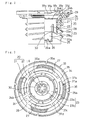
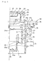
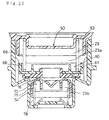
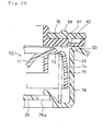
- the fuel tank cap 10 includes a casing body 20 composed of a synthetic resin material, such as, for example, polyacetal, a cover member 40 attached to an upper portion of the casing body 20 and composed of a synthetic resin material, such as, for example, nylon, an inner cover 50 for closing an upper opening of the casing body 20 to define a valve chamber 23, a positive pressure valve 60 and a negative pressure valve 70 received in the valve chamber 23 to function as pressure control valves, and a gasket GS attached to the upper circumference of the casing body 20 for sealing the casing body 20 from the filler neck FN.
- a synthetic resin material such as, for example, polyacetal
- cover member 40 attached to an upper portion of the casing body 20 and composed of a synthetic resin material, such as, for example, nylon
- an inner cover 50 for closing an upper opening of the casing body 20 to define a valve chamber 23, a positive pressure valve 60 and a negative pressure valve 70 received in the valve chamber 23 to function as pressure control valves, and a gasket GS attached to
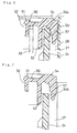
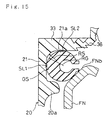
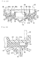
- the valve body 61 When the seat surface 62 is pressed against the seat member 30, the valve body 61 is seated onto the seat member 30 while keeping the horizontal attitude and being supported by the valve support member 68 on both the inner circumferential side and the outer circumferential side of the ring recess 64.
- the seat surface 62 is in line contact with the ridge of the seat member 30 and is seated not in the inclined attitude but in the horizontal attitude, thereby ensuring high sealing property.
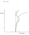
- the small contact area between the seat surface 62 and the seat member 30 realizes the ideal valve-opening characteristic, that is, an abrupt rise in the open position.
- the ring groove 61b is formed in the seat surface 62 of the valve body 61 to equalize the deflection in the vicinity of the ring recess 64 of the seat surface 62, thereby further improving the sealing property.
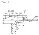
- the conditions of electric discharge whereby the user is not shocked when removing the fuel tank cap 10 are: (1) that discharge of electricity is securely performed irrespective of the closing state of the fuel tank cap 10; and (2) that discharge of electricity proceeds gently and does not cause a large shock.
- the discharge projections 46 have the following structure in order to satisfy these conditions.
Landscapes
- Engineering & Computer Science (AREA)
- Life Sciences & Earth Sciences (AREA)
- Sustainable Development (AREA)
- Sustainable Energy (AREA)
- Chemical & Material Sciences (AREA)
- Combustion & Propulsion (AREA)
- Transportation (AREA)
- Mechanical Engineering (AREA)
- Closures For Containers (AREA)
- Cooling, Air Intake And Gas Exhaust, And Fuel Tank Arrangements In Propulsion Units (AREA)
Claims (8)
- Kraftstofftankdeckel (10), der einen Einlaß (FNb) eines Einfüllstutzens (FN) eines Kraftstofftanks öffnet und schließt, wobei der Kraftstofftankdeckel (10) ein Drucksteuerventil und einen zur Anbringung an dem Einfüllstutzen (FN) angeordneten Gehäusekörper (20) umfaßt, und das Drucksteuerventil
einen mit dem Einfüllstutzen (FN) durch einen Kanal verbundenes Sitzteil (30),
einen scheibenförmigen Ventilkörper (61) mit einer zum Sitz auf dem Sitzteil (30) angeordneten Sitzfläche (62) und einer der Sitzfläche (62) gegenüberliegenden hinteren Fläche (62a), und
ein mit der hinteren Fläche (62a) zum Lagern des Ventilkörpers (61) in Berührung stehendes Ventillagerteil (68) umfaßt,
dadurch gekennzeichnet, dass
der Ventilkörper (61) eine ringförmige Aussparung (64) umfaßt, die einen dünnwandigen Sitzabschnitt unter der Sitzfläche (62) bildet, dass das Sitzteil zum Sitz an der Mitte des dünnwandigen Sitzabschnitts angeordnet ist, und dass die hintere Fläche (62a) mittels des Ventillagerteils (68) abgedeckt ist. - Kraftstofftankdeckel (10) nach Anspruch 1, wobei das Drucksteuerventil ein positives Druckventil (60) umfaßt, das öffnet, wenn der Druck in dem Kraftstofftank um mindestens einen bestimmten Wert größer als der atmosphärische Druck ist.
- Kraftstofftankdeckel (10) nach Anspruch 2, wobei der Ventilkörper (61) eine mit dem Kanal verbundene Ventilströmungsöffnung (63) aufweist, und das Ventillagerteil (68) ein scheibenförmiges Teil mit einer Paßöffnung (68a) umfaßt, wobei die Paßöffnung (68a) das Paßstück (65) des Ventilkörpers (61) darin passend aufnimmt, um somit zusätzlich den Ventilkörper (61) zu befestigen.
- Kraftstofftankdeckel (10) nach Anspruch 3, wobei das positive Druckventil (60) eine Schraubenfeder (69) umfaßt, und das Ventillagerteil (68) den Ventilkörper (61) lagert, wodurch der Ventilkörper (61) gegen das Sitzteil (30) mittels der Druckkraft der Schraubenfeder (69) gedrückt wird.
- Kraftstofftankdeckel nach Anspruch 4, wobei der Ventilkörper (61) eine Ringnut (61b) umfaßt, die an eine innere Umfangsseite von und konzentrisch mit der ringförmigen Aussparung (64) ausgebildet ist.
- Kraftstofftankdeckel nach Anspruch 5, wobei das Drucksteuerventil ein negatives Drucksteuerventil (70) umfaßt, das öffnet, wenn der Druck des Kraftstofftanks um einen bestimmten Wert niedriger als der atmosphärische Druck ist, und das negative Druckventil (70) einen Ventilkörper (71) umfaßt, der zum Sitz auf der Innenseite der ringförmigen-Aussparung (64) angeordnet ist.
- Kraftstofftankdeckel nach Anspruch 1, wobei der Gehäusekörper (20) ein Ventilkammer bildenden Teil (22) mit einem oberen zylindrischen Wandelement (24), einem unteren zylindrischen Wandelement (25), das einen kleineren Durchmesser als das obere zylindrische Wandelement aufweist, und ein am unteren Abschnitt des unteren zylindrischen Wandelements (25) ausgebildetes Bodenelement (26) umfaßt, und das obere zylindrische Wandelement (24) einstückig, napfförmig ausgebildet ist und wobei
das Sitzteil (30) eine geneigte Ebene (30a) zur Verbindung des oberen zylindrischen Wandelements (24) mit dem unteren Wandelement (25) umfaßt. - Kraftstofftankdeckel nach Anspruch 7, wobei die geneigte Ebene (30a) in einem Winkel von nicht größer als 30° in bezug auf eine axiale Richtung des Gehäusekörpers (20) geneigt ist.
Applications Claiming Priority (3)
| Application Number | Priority Date | Filing Date | Title |
|---|---|---|---|
| JP97965/97 | 1997-03-31 | ||
| JP9796597 | 1997-03-31 | ||
| JP09796597A JP3991387B2 (ja) | 1997-03-31 | 1997-03-31 | 燃料キャップ |
Publications (3)
| Publication Number | Publication Date |
|---|---|
| EP0869023A2 EP0869023A2 (de) | 1998-10-07 |
| EP0869023A3 EP0869023A3 (de) | 2000-03-22 |
| EP0869023B1 true EP0869023B1 (de) | 2005-06-01 |
Family
ID=14206394
Family Applications (1)
| Application Number | Title | Priority Date | Filing Date |
|---|---|---|---|
| EP98105748A Expired - Lifetime EP0869023B1 (de) | 1997-03-31 | 1998-03-30 | Kraftstofftankdeckel |
Country Status (4)
| Country | Link |
|---|---|
| US (1) | US5996829A (de) |
| EP (1) | EP0869023B1 (de) |
| JP (1) | JP3991387B2 (de) |
| DE (1) | DE69830355T2 (de) |
Families Citing this family (21)
| Publication number | Priority date | Publication date | Assignee | Title |
|---|---|---|---|---|
| US6179148B1 (en) * | 1997-07-23 | 2001-01-30 | Stant Manufacturing Inc. | Fuel cap |
| EP1124725B1 (de) | 1998-07-10 | 2004-04-14 | Stant Manufacturing Inc. | Einfüllstutzenverschluss |
| US6508374B1 (en) * | 1999-11-04 | 2003-01-21 | Stant Manufacturing Inc. | Filler neck closure with static charge dissipater |
| DE10001428A1 (de) * | 2000-01-15 | 2001-11-29 | Volkswagen Ag | Kraftstoffanlage für eine Brennkraftmaschine mit einer Einrichtung zum Auffangen und Sammeln von Kraftstoffdämpfen |
| US6273286B1 (en) | 2000-04-12 | 2001-08-14 | Evergreen Custom Molding, Inc. | Ventilating system |
| EP1162099B1 (de) * | 2000-06-07 | 2004-09-15 | Toyoda Gosei Co., Ltd. | Tankverschluss and Tankverschlussvorrichtung |
| US6364145B1 (en) | 2000-08-21 | 2002-04-02 | Richard J. Shaw | Motor vehicle fuel cap inlet and outlet vent apparatus |
| US7780603B2 (en) | 2000-09-25 | 2010-08-24 | Welch Allyn, Inc. | Blood pressure measuring apparatus |
| AU2001292669A1 (en) | 2000-09-25 | 2002-04-08 | Welch Allyn, Inc. | Blood pressure measuring apparatus |
| US7163117B2 (en) * | 2002-05-01 | 2007-01-16 | Stant Manufacturing Inc. | Static charge dissipater for filler neck closure |
| US7578405B2 (en) | 2003-09-04 | 2009-08-25 | Toyoda Gosei Co., Ltd. | Fuel cap having a fuel tank pressure regulating valve |
| JP4380472B2 (ja) | 2004-08-30 | 2009-12-09 | 豊田合成株式会社 | 燃料キャップ |
| CN100352686C (zh) * | 2004-09-08 | 2007-12-05 | 丰田合成株式会社 | 闭锁体及燃料箱的燃料供给装置 |
| US20060124644A1 (en) * | 2004-12-13 | 2006-06-15 | James Dehn | Ratcheted fuel cap |
| US7234356B2 (en) * | 2005-03-16 | 2007-06-26 | Welch Allyn, Inc. | Shock resistant blood pressure measuring apparatus |
| TWI316908B (en) * | 2005-06-23 | 2009-11-11 | Honda Motor Co Ltd | Tank cap |
| US8813780B2 (en) * | 2010-10-26 | 2014-08-26 | Schiller Grounds Care, Inc. | Sealed, non-permeable fuel tank for spark-ignition motors |
| JP5630420B2 (ja) * | 2011-10-28 | 2014-11-26 | 豊田合成株式会社 | 燃料キャップ |
| JP5907028B2 (ja) * | 2012-09-28 | 2016-04-20 | 豊田合成株式会社 | 燃料タンクの開閉装置 |
| CN104482214B (zh) * | 2014-12-27 | 2016-05-18 | 安徽江淮汽车股份有限公司 | 一种密封圈结构 |
| USD1015152S1 (en) * | 2021-07-26 | 2024-02-20 | Arman Simonyan | Gas cap container lid |
Family Cites Families (17)
| Publication number | Priority date | Publication date | Assignee | Title |
|---|---|---|---|---|
| US3831801A (en) * | 1972-11-20 | 1974-08-27 | Stant Mfg Co | Pressure-vacuum valved cap |
| US3937357A (en) * | 1973-09-20 | 1976-02-10 | Tom Mcguane Industries, Inc. | Pressure-vacuum relief fuel filler cap |
| US4498493A (en) * | 1981-06-24 | 1985-02-12 | Stant Inc. | Pressure valve assembly for a fuel tank filler neck cap |
| JPS60116974A (ja) * | 1983-11-29 | 1985-06-24 | Toyoda Gosei Co Ltd | 弁付キヤツプ |
| JPS60179654U (ja) * | 1984-05-07 | 1985-11-29 | 豊田合成株式会社 | 弁付キヤツプ |
| JPS60193050U (ja) * | 1984-05-30 | 1985-12-21 | 豊田合成株式会社 | 弁付キヤツプ |
| US4561559A (en) * | 1984-11-07 | 1985-12-31 | Deere & Company | Fuel tank venting valve |
| JPS61180962U (de) * | 1985-04-27 | 1986-11-11 | ||
| JPS62168867A (ja) * | 1986-01-17 | 1987-07-25 | 豊田合成株式会社 | 弁付キヤツプ |
| US4795050A (en) * | 1986-03-31 | 1989-01-03 | Stant Inc. | Two-stage fuel cap |
| JPH0424849Y2 (de) * | 1986-08-30 | 1992-06-12 | ||
| US4815705A (en) * | 1986-11-27 | 1989-03-28 | Toyoda Gosei Co., Ltd. | Valve body |
| JPH06102469B2 (ja) * | 1986-12-26 | 1994-12-14 | 豊田合成株式会社 | 弁付キヤツプ |
| JPH0647796Y2 (ja) * | 1987-05-29 | 1994-12-07 | 豊田合成株式会社 | 正圧弁付キヤツプ |
| JPH0688606B2 (ja) * | 1987-10-15 | 1994-11-09 | 豊田合成株式会社 | フユーエルキヤツプ |
| JP2611785B2 (ja) * | 1987-10-24 | 1997-05-21 | 豊田合成株式会社 | フユーエルキヤツプ |
| JPH0688606A (ja) | 1992-09-09 | 1994-03-29 | Mitsubishi Heavy Ind Ltd | ガス発生装置を有する石炭燃焼炉 |
-
1997
- 1997-03-31 JP JP09796597A patent/JP3991387B2/ja not_active Expired - Lifetime
-
1998
- 1998-03-30 DE DE69830355T patent/DE69830355T2/de not_active Expired - Lifetime
- 1998-03-30 EP EP98105748A patent/EP0869023B1/de not_active Expired - Lifetime
- 1998-03-31 US US09/050,955 patent/US5996829A/en not_active Expired - Lifetime
Also Published As
| Publication number | Publication date |
|---|---|
| DE69830355T2 (de) | 2006-01-26 |
| DE69830355D1 (de) | 2005-07-07 |
| EP0869023A2 (de) | 1998-10-07 |
| US5996829A (en) | 1999-12-07 |
| EP0869023A3 (de) | 2000-03-22 |
| JPH10278958A (ja) | 1998-10-20 |
| JP3991387B2 (ja) | 2007-10-17 |
Similar Documents
| Publication | Publication Date | Title |
|---|---|---|
| EP0869023B1 (de) | Kraftstofftankdeckel | |
| EP0869028B1 (de) | Kraftstofftankdeckel | |
| EP0869024B1 (de) | Kraftstofftankdeckel und Verfahren zu seiner Herstellung | |
| EP0869027B1 (de) | Kraftstofftankdeckel | |
| EP0869025B1 (de) | Kraftstofftankdeckel und Verfahren zu seiner Herstellung | |
| US20100218849A1 (en) | Fuel tank opening-closing device | |
| EP0869026B1 (de) | Kraftstofftankdeckel | |
| US20030173362A1 (en) | Fuel cap | |
| EP0827914B1 (de) | Kraftstoffkappe | |
| CN100363207C (zh) | 车辆用燃油加注口盖 | |
| JPS5851485B2 (ja) | ジドウシヤノネンリヨウタンクノタメノ チユウユウブコウゾウ | |
| JP3849610B2 (ja) | 燃料キャップ | |
| JP3200732B2 (ja) | フューエルキャップ | |
| CN223199781U (zh) | 螺母盖板固定结构和具有其的车辆 | |
| JP2022143182A (ja) | 車両の開閉体構造 | |
| JPH0234213Y2 (de) | ||
| JPS6026472Y2 (ja) | プラグキヤツプ | |
| JPH0819422A (ja) | 棒状化粧料容器 | |
| JPH08254239A (ja) | ショックアブソーバ | |
| JPS6313170Y2 (de) | ||
| KR19980015615U (ko) | 자동차 연료주입구의 인너캡(Inner Cap) | |
| JPH06227271A (ja) | 車両用燃料タンクの注入管の保護構造 |
Legal Events
| Date | Code | Title | Description |
|---|---|---|---|
| PUAI | Public reference made under article 153(3) epc to a published international application that has entered the european phase |
Free format text: ORIGINAL CODE: 0009012 |
|
| 17P | Request for examination filed |
Effective date: 19980330 |
|
| AK | Designated contracting states |
Kind code of ref document: A2 Designated state(s): DE FR GB |
|
| PUAL | Search report despatched |
Free format text: ORIGINAL CODE: 0009013 |
|
| AK | Designated contracting states |
Kind code of ref document: A3 Designated state(s): AT BE CH DE DK ES FI FR GB GR IE IT LI LU MC NL PT SE |
|
| AX | Request for extension of the european patent |
Free format text: AL;LT;LV;MK;RO;SI |
|
| AKX | Designation fees paid |
Free format text: DE FR GB |
|
| GRAP | Despatch of communication of intention to grant a patent |
Free format text: ORIGINAL CODE: EPIDOSNIGR1 |
|
| GRAS | Grant fee paid |
Free format text: ORIGINAL CODE: EPIDOSNIGR3 |
|
| GRAA | (expected) grant |
Free format text: ORIGINAL CODE: 0009210 |
|
| AK | Designated contracting states |
Kind code of ref document: B1 Designated state(s): DE FR GB |
|
| REG | Reference to a national code |
Ref country code: GB Ref legal event code: FG4D |
|
| REF | Corresponds to: |
Ref document number: 69830355 Country of ref document: DE Date of ref document: 20050707 Kind code of ref document: P |
|
| ET | Fr: translation filed | ||
| PLBE | No opposition filed within time limit |
Free format text: ORIGINAL CODE: 0009261 |
|
| STAA | Information on the status of an ep patent application or granted ep patent |
Free format text: STATUS: NO OPPOSITION FILED WITHIN TIME LIMIT |
|
| 26N | No opposition filed |
Effective date: 20060302 |
|
| PGFP | Annual fee paid to national office [announced via postgrant information from national office to epo] |
Ref country code: FR Payment date: 20100324 Year of fee payment: 13 |
|
| PGFP | Annual fee paid to national office [announced via postgrant information from national office to epo] |
Ref country code: GB Payment date: 20100322 Year of fee payment: 13 |
|
| GBPC | Gb: european patent ceased through non-payment of renewal fee |
Effective date: 20110330 |
|
| REG | Reference to a national code |
Ref country code: FR Ref legal event code: ST Effective date: 20111130 |
|
| PG25 | Lapsed in a contracting state [announced via postgrant information from national office to epo] |
Ref country code: FR Free format text: LAPSE BECAUSE OF NON-PAYMENT OF DUE FEES Effective date: 20110331 |
|
| PG25 | Lapsed in a contracting state [announced via postgrant information from national office to epo] |
Ref country code: GB Free format text: LAPSE BECAUSE OF NON-PAYMENT OF DUE FEES Effective date: 20110330 |
|
| PGFP | Annual fee paid to national office [announced via postgrant information from national office to epo] |
Ref country code: DE Payment date: 20170321 Year of fee payment: 20 |
|
| REG | Reference to a national code |
Ref country code: DE Ref legal event code: R071 Ref document number: 69830355 Country of ref document: DE |