EP0870620B1 - Appareil d'enregistrement thermique avec des moyens pour ameliorer l'alignement de la tête thermique par rapport au cylindre d'appui - Google Patents
Appareil d'enregistrement thermique avec des moyens pour ameliorer l'alignement de la tête thermique par rapport au cylindre d'appui Download PDFInfo
- Publication number
- EP0870620B1 EP0870620B1 EP98106518A EP98106518A EP0870620B1 EP 0870620 B1 EP0870620 B1 EP 0870620B1 EP 98106518 A EP98106518 A EP 98106518A EP 98106518 A EP98106518 A EP 98106518A EP 0870620 B1 EP0870620 B1 EP 0870620B1
- Authority
- EP
- European Patent Office
- Prior art keywords
- thermal head
- head bar
- bar
- platen roller
- thermal
- Prior art date
- Legal status (The legal status is an assumption and is not a legal conclusion. Google has not performed a legal analysis and makes no representation as to the accuracy of the status listed.)
- Expired - Lifetime
Links
Images


Classifications
-
- B—PERFORMING OPERATIONS; TRANSPORTING
- B41—PRINTING; LINING MACHINES; TYPEWRITERS; STAMPS
- B41J—TYPEWRITERS; SELECTIVE PRINTING MECHANISMS, i.e. MECHANISMS PRINTING OTHERWISE THAN FROM A FORME; CORRECTION OF TYPOGRAPHICAL ERRORS
- B41J11/00—Devices or arrangements of selective printing mechanisms, e.g. ink-jet printers or thermal printers, for supporting or handling copy material in sheet or web form
- B41J11/02—Platens
- B41J11/04—Roller platens
-
- B—PERFORMING OPERATIONS; TRANSPORTING
- B41—PRINTING; LINING MACHINES; TYPEWRITERS; STAMPS
- B41J—TYPEWRITERS; SELECTIVE PRINTING MECHANISMS, i.e. MECHANISMS PRINTING OTHERWISE THAN FROM A FORME; CORRECTION OF TYPOGRAPHICAL ERRORS
- B41J11/00—Devices or arrangements of selective printing mechanisms, e.g. ink-jet printers or thermal printers, for supporting or handling copy material in sheet or web form
- B41J11/20—Platen adjustments for varying the strength of impression, for a varying number of papers, for wear or for alignment, or for print gap adjustment
Definitions
- the present invention relates to a thermal recorder, and more particularly, to an improvement of a thermal head bar support construction of the thermal recorder in view of the positioning of a thermal head bar relative to a platen roller.
- a thermal recorder having a thermal head bar bearing a linear array of a number of heat generating elements and a platen roller between which a thermally recording sheet such as a thermally perforatable stencil or a thermally chromophoric sheet is clamped and transferred in a direction of traversing the array of heat generating elements according to a rotation of the platen roller such that an image is generated in the thermally recording sheet by a digital heat generating actuation of the respective heat generating elements according to an image signal
- the platen roller is mounted to either of a housing of the recorder and a cover pivotably mounted to the housing to be pivotable between an open position and a closed position
- the thermal head bar is mounted to the other of the housing and the cover, wherein the platen roller and the thermal head bar are pressed to one another with the array of heat generating elements of the thermal head bar being aligned to a generatrix of a cylindrical surface of the platen roller when the cover is in the closed position, while the platen roller and
- the precision with regard to how the array of heat generating elements of the thermal head bar is correctly aligned with a generatrix of the cylindrical surface of the platen roller and the precision with regard to how the thermal head bar and the platen roller are longitudinally correctly positioned relative to one another are dependent upon the precision of the pivotal opening and closing movement of the cover relative to the housing.
- the radius of the pivotal movement of the thermal head bar or the platen roller in the opening and closing of the cover is generally designed to be at least 15cm.
- an allowance of errors in the manufacture of the covers and the assembling of the covers to the housings should be, for example, 0.2% of the radius of pivotal movement of the thermal head bar or the platen roller, when the pivotal radius is, for example, 15cm, the absolute error in the radius of the pivotal movement would reach 0.3mm.
- Such an error is very substantial, as it is approximately 10% for an image like characters of a height of a few mm.
- Document EP-A-0 311 982 discloses a thermal recorder comprising a housing, a cover mounted to the housing to be pivotable between an open position and a closed position, a platen roller mounted to the housing and a thermal head bar having an array of heat generating elements and mounted to the cover, the thermal head bar and the platen roller being adapted to be pressed together when the cover is in the closed position with the array of heat generating elements of the thermal head bar being laid on a cylindrical surface of the platen roller along a generatrix thereof and to be detached from one another when the cover is in the open position, wherein the thermal head bar has a pair of forks at longitudinally opposite ends thereof, while the platen roller has a pair of circular radial cams arranged coaxially thereto at opposite ends thereof and adapted to be engaged in a corresponding groove of each of the forks so as to radially align the thermal head bar with the platen roller when the thermal head bar and the platen approach to one another, the thermal head bar being mounted to the cover at
- a thermal recorder comprising a housing, a cover pivotably mounted to said housing to be movable between an open position and a closed position relative to said housing, a platen roller mounted to either one of said housing and said cover, and a thermal head bar mounted to other one of said housing and said cover, said thermal head bar and said platen roller being adapted to be pressed together when said cover is in said closed position with an array of heat generating elements of said thermal head bar being laid on a cylindrical surface of said platen roller along a generatrix thereof and to be detached from one another when said cover is in said open position, wherein said thermal head bar has a pair of forks at longitudinally opposite ends thereof, while said platen roller has a pair of circular radial cams arranged coaxially thereto at opposite ends thereof and adapted to be engaged in a corresponding groove of each of said forks so as to radially align said thermal head bar with said platen roller when said thermal head bar and said platen approach
- the mounting of said thermal head bar to the other of said housing and said cover may be made via a support bar laid over said thermal head bar therealong on one side thereof opposite to other side thereof where said array of heat generating elements is provided, said support bar having an opening at a longitudinally central portion thereof elongated in the direction of extension of said thermal head bar, said thermal head bar being connected with said support bar by a headed bolt passed through said elongated opening except a head portion thereof and planted into said thermal head bar such that said thermal head bar is restricted by said headed bolt against a movement thereof relative to said support bar in a direction of detaching therefrom but can rock around the head portion of said headed bolt within a small angle and also can shift in a longitudinal direction of said support bar relative thereto within a small distance.
- Said support bar may have a bearing opening at a longitudinally central portion thereof, said bearing opening being directed perpendicular to both a direction of longitudinal extension of said support bar and a direction of extension of said grooves of said forks, and a support pin may be passed through said bearing opening and mounted to the other of said housing and said cover, so that said support bar is shiftable along said support pin within a small distance and also tiltable relative thereto within a small angle.
- Said thermal head bar and said support bar may be mutually approachable under a restriction by a plurality of washers disposed linearly along a rear surface of said thermal hear bar exactly opposite to a linear portion thereof where said array of heat generating elements is provided.
- Said washers may each be engaged with said support bar and are each slidable over the rear surface of said thermal head bar.
- 10 is a platen roller
- 12 is a thermal head bar.
- the platen roller 10 is supported by a shaft 14 extending along the central axis thereof, with opposite ends of the shaft 14 being rotatably mounted to a housing 16.
- the thermal head bar 12 is an elongated member having a substantially rectangular cross section, and carries a large number of heat generating elements disposed as an array thereof along a linear portion extending in the longitudinal direction of a front surface 18 facing the platen roller 10, though not shown in the figure.
- the thermal head bar 12 is engaged with a support bar 22 arranged to extend along a rear surface 20 thereof opposite to the front surface 18 in close proximity thereto in a manner described hereinbelow.
- the support bar 22 has a pair of support lug portions 24 in which bearing openings 26 are formed to bear a pair of bearing pushes 28 through which a support pin 30 is inserted and mounted to a support rod 33 which in turn is supported by a cover 34 of the thermal recorder.
- the pair of support lug portions 24 of the support bar 22 are shiftable along the support pin 30 within a small distance between a stopper 31 mounted to the support pin 30 and an annular end face of a larger diameter portion 32 of the support pin 30.
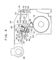
- the cover 34 is pivotably mounted to the housing 16 by a pivot shaft 36, so that the cover 34 is pivotable between a closed position for pressing the thermal head bar 12 to the platen roller 10 as shown in Fig. 4 and an open position for detaching the thermal head bar 12 from the platen roller 10 as shown in Fig. 5.
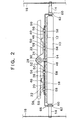
- the support bar 22 is a member made of a relatively thin metal plate worked as shown in Fig. 1, so as to have a flat main portion 38 arranged to lay over the thermal head bar 12, rib portions 40 and 42 bent along opposite sides of the main portion, the above-mentioned pair of support lug portions 24 projecting from the rib portions, a pair of horizontal tilt restricting lug portions 44 bent downward from one side edge of the main portion 28, and a pair of vertical tilt restricting lug portions 46 extending upward from the rib portion 40 and then bent in a horizontal direction.
- the support bar 22 is formed with an elongated opening 48 at a longitudinally central portion thereof vertically aligned with the bearing openings 26, and four circular openings 50 longitudinally aligned with the elongated opening 48 on opposite sides thereof.
- a headed bolt 54 having a head portion 52 is passed through the elongated opening 48 with its shank portion by leaving the head portion 52 above the main portion 38, so that the shank portion is planted into the thermal head bar 12.
- a movement of the support bar 22 in the direction of detaching from the thermal head bar 12 is restricted by the head portion 52 of the headed bolt 54 engaging the upper surface of the main portion 38 along the periphery of the elongated opening 48.
- a washer 58 having a projection 56 extending upward through the circular opening.
- the base portions of the washers 58 work as a spacer for maintaining a constant clearance between the main portion 38 of the support bar 22 and the thermal head bar 12.
- the lower end portions of the pair of horizontal tilt restricting lug portions 44 are each spaced slightly from a side edge of the thermal head bar 12, so that a horizontal relative tilt movement between the thermal head bar 12 and the support bar 22 around the headed bolt 54 is restricted within a small angle by either one of the lug portions 44 abutting the side edge of the thermal head bar 12.
- the pair of vertical tilt restricting lug portions 46 are slightly spaced from a lower surface of the support rod 33, so that a vertical tilt movement of the support bar 22 relative to the support rod 33 around the support pin 30 is restricted within a small angle by either one of the lug portions 46 abutting the lower surface of the support rod 33.
- the support rod 33 is pivotably mounted to the cover 34 at opposite ends thereof, and is adapted to be selectively biased to rotate around a central axis thereof in the clockwise direction as viewed in Figs. 4 and 5, by a solenoid means not shown in the figure, when the thermal head bar 12 is pressed against the platen roller 10 as shown in Fig. 4, thereby setting up a pressing force at a value proper for the execution of the thermal recording.
- the restriction of tilting of support bar 22 around the support pin 30 against the support rod 33 is the restriction of tilting of the support bar 22 around the support pin 30 against the cover 34.
- the elongated opening 48 and the circular openings 50 of the support bar 22 are aligned along a straight line in the longitudinal direction of the support bar 22, while the center of the headed bolt 54 engaged in the elongated opening 48 is in alignment with the array of heat generating elements arranged along a straight line in the longitudinal direction of the front surface 18 of the thermal head bar 12. It is desirable that a small clearance is left between the head portion 52 of the headed bolt 54 and the upper surface of the main portion 38 of the support bar 22, so that the thermal head bar 12 can tilt within a small angle relative to the support bar 22 as viewed in the longitudinal direction thereof, i.e. in the direction following the axis of the platen roller, before the thermal head bar 12 is firmly pressed against the platen roller 10 by the support bar 22 as shown in Figs 2 and 4.
- the thermal head bar 12 can move relative to the cover 34 within a small distance in the longitudinal direction thereof as much as the headed bolt 54 can shift in the elongated opening 48, can also move relative to the cover 34 within a small distance as much as the bearing openings 26 of the support lug portions of the support bar 22 can move along the support pin 30 between the stopper 31 and the annular end face of the larger diameter portion 32 of the support pin 30, can also tilt relative to the cover 34 within a small angle as much as the support bar 22 is allowed to rotate around the headed bolt 54 until the clearance between the horizontal tilt restricting lug portions 44 and the side edge of the thermal head bar 12 is canceled, and also can tilt relative to the cover 34 within a small angle as much as the support bar 22 is allowed to rotate around the support pin 30 until the clearance between the vertical tilt restricting lug portions 46 and the support rod 33 is canceled.
- the thermal head bar 12 is mounted to the cover 34 in a condition that it can tilt relative to the cover 34 within a small angle around an axis extending longitudinally along substantially the upper or lower surface of the main portion 38 of the support bar 22 through centers of the elongated opening 48 and the circular openings 50.
- it is the thermal head bar 12 which is mounted to the cover 34, while it is the platen roller 10 which is mounted to the housing 16.
- the thermal head bar may be mounted to the housing in the same manner with a support bar so that a small play is allowed, while the platen roller may be mounted to the cover.
- a radial cam 60 is provided at each of the opposite ends of the platen roller 10 along a portion of the shaft 14, and corresponding thereto a fork 62 is provided at each of the opposite ends of the thermal head bar 12.
- the forks 62 have each a groove 64 adapted to receive the radial cam 60 therein when the platen roller 10 and the thermal head bar 12 approach to one another.
- the engagement of the forks and the radial cams restricts the relationship between the platen roller and the thermal head bar in the radially aligned state.
- the array of heat generating elements provided in the front surface 18 of the thermal head bar 12 contact the cylindrical surface of the platen roller 10 along a generatrix thereof.
- At least one of the opposite ends of the platen roller 10 there is provided an axial cam 66 adapted to engage with the groove 64 of a corresponding one of the forks 62, so as to restrict the axial relative position between the thermal head bar and the platen roller.
- the axial cam 66 has a pair of conically oblique surfaces positioned on axially opposite sides of a cylindrical portion serving as the radial cam 60, so that when the fork 62 approaches thereto, the groove 64 of the fork is engaged by the axial cam 66, thereby conducting the axial relationship therebetween to be as predetermined.
- the thermal head bar 12 being mounted to the cover 34 with a small play, while the radial alignment of the thermal head bar 12 relative to the platen roller 10 is restricted by the engagement of the radial cams 60 provided at the opposite ends of the platen roller with the forks 62 provided at the opposite ends of the thermal head bar 12, with a further restriction by the engagement between the axial cam 62 provided at least one of the opposite ends of the platen roller and the fork 62 provided at the corresponding end of the thermal head bar for restricting the axial relationship between the platen roller and the thermal head bar, even when the allowance of precision in the manufacture of the covers and that in the assembling of the covers to the housings by the pivot shafts 36 are relatively moderate, when the thermal head bar 12 and the platen roller 10 are finally pressed together, the radial alignment between the thermal head bar 12 and the platen roller 10, i.e.
- the alignment between the array of heat generating elements and the cylindrical surface of the platen roller is maintained to be an allowance of manufacture for a dimension of the order of 10mm, so that if, for example, the allowance of manufacture is 0.2%, the absolute error in engagement is suppressed to the order of 0.02mm.
- a similar precision is available with respect to the axial positioning between the platen roller and the thermal head bar.
- the pair of radial cams 60 on the side of the platen roller and the pair of forks 62 on the side of the thermal head bar can smoothly and lightly enter into engagement with one another.
- the correct radial alignment is automatically accomplished by the support lug portions 24 of the support bar 22 slide appropriately along the support pin 30 at the bearing openings 26 thereof.
- 68 is a hook member pivotably mounted to the cover 34 by a pivot shaft 70.
- the hook member 68 is biased around the pivot shaft 70 in the anti-clockwise direction by a tension coil spring 72, so as to be kept in engagement with a stop pin 74 mounted to the housing 16, thereby maintaining the cover 34 in the closed position when it was once closed.
- the hook member 68 is turned against the spring force of the tension coil spring 72 by a lever portion 76 thereof being pulled forward, so that it is released from the engagement with the stop pin 74.
- a coil 78 of a thermally recording sheet such as a thermal stencil is charged in the housing, so that a thermally recording sheet 80 is pulled out therefrom to be transferred through between the thermal head bar 12 and the platen roller 10 as pressed therebetween according to the rotation of the platen roller 10 and forwarded through a pair of guide rollers 82 and 84 toward a processing unit such as a printing drum.
- the thermal head bar is mounted to the cover or a housing of with two linear small plays and two small rotational plays, while forks provided at opposite longitudinal ends of the thermal head bar and radial cams provided at opposite ends of the platen roller are engaged with one another to restrict a radial alignment of the thermal head bar and the platen roller, while the fork provided at least at one longitudinal end of the thermal head bar and an axial cam provided at a corresponding end of the platen roller are engaged with one another to restrict an axial alignment of the thermal head bar and the platen roller.
Landscapes
- Electronic Switches (AREA)
- Common Mechanisms (AREA)
Claims (5)
- Appareil d'enregistrement thermique comportant un boítier, un capot monté sur ledit boítier pour pivoter entre une position d'ouverture et une position de fermeture, un rouleau d'appui monté sur l'un du boítier ou du capot et une barre de tête thermique ayant un réseau d'éléments générateurs de chaleur et montée sur l'autre dudit boítier ou dudit capot, ladite barre de tête thermique et ledit rouleau d'appui étant adaptés pour être pressés l'un contre l'autre lorsque ledit capot se trouve dans ladite position de fermeture avec ledit réseau d'éléments générateurs de chaleur de ladite barre de tête thermique qui est appliquée contre la surface cylindrique dudit rouleau d'appui le long d'une génératrice de celui-ci et être séparés l'un de l'autre lorsque ledit capot est dans ladite position de fermeture, ladite barre de tête thermique ayant une paire de fourches à ses deux extrémités opposées, tandis que ledit rouleau d'appui a une paire de cames circulaires radiales, disposées coaxialement à lui à ses extrémités opposées et adaptées pour s'engager dans une gorge correspondante de chacune desdites fourches de façon à aligner radialement ladite barre de tête thermique avec ledit rouleau d'appui lorsque ladite barre de tête thermique et ledit rouleau d'appui se rapprochent, ledit rouleau d'appui ayant en outre une came axiale à au moins une de ses extrémités, adaptée pour s'engager dans l'une desdites fourches de façon à réduire une position longitudinale relative entre ladite barre de tête thermique et ledit rouleau d'appui, ladite barre de tête thermique étant montée sur l'autre dudit boítier ou dudit capot sur une zone longitudinale centrale de celui-ci avec un faible jeu de mouvement, qui comporte un léger décalage dans une première direction d'extension longitudinale de ladite barre de tête thermique, un léger décalage dans une seconde direction essentiellement perpendiculaire à la fois à ladite première direction et à une direction d'extension desdites gorges desdites fourches, et une faible rotation autour de chacun de deux axes qui sont perpendiculaires à ladite première direction aussi bien qu'entre eux.
- Appareil d'enregistrement thermique selon la revendication 1, dans lequel le montage de ladite barre de tête thermique sur l'autre dudit boítier ou dudit capot, est effectué grâce à une barre-support disposée au-dessus ce ladite barre de tête thermique, le long de celle-ci, sur l'un de ses côtés opposé l'autre côté où ledit réseau d'éléments générateurs de chaleur est disposé, ladite barre-support ayant une ouverture dans une zone centrale longitudinale de celle-ci, allongée en direction de l'extension de ladite barre de tête thermique, ladite barre de tête thermique étant reliée à ladite barre-support par un boulon à tête à travers ladite ouverture à l'exception d'une portion de tête et planté dans ladite barre de tête thermique de sorte que ladite barre de tête thermique est limitée par ledit boulon à tête dans son mouvement relativement à ladite barre-support dans le sens d'une séparation d'avec elle mais peut tourner autour de la portion de tête dudit boulon à tête sur un petit angle et également se déplacer dans une direction longitudinale de ladite barre-support, par rapport à elle, d'une courte distance.
- Appareil d'enregistrement thermique selon la revendication 2, dans lequel ladite barre-support a une ouverture de palier dans une zone longitudinale centrale, ladite ouverture de palier étant dirigée perpendiculairement à la fois à la direction de l'extension longitudinale de ladite barre-support et à une direction d'extension desdites gorges desdites fourches, un axe de support traversant lesdites ouvertures de palier étant monté sur l'autre dudit boítier ou dudit capot de sorte que ladite barre-support peut coulisser le long dudit axe de support sur une courte distance et est pivotable par rapport à lui sur un petit angle.
- Appareil d'enregistrement thermique selon la revendication 2, dans lequel ladite barre de tête thermique et ladite barre-support peuvent être mutuellement rapprochées avec une limitation par une pluralité de rondelles disposées alignées le long d'une surface arrière de ladite barre de tête thermique exactement à l'opposé d'une portion linéaire de celle-ci où ledit réseau d'éléments générateurs de chaleur est disposé.
- Appareil d'enregistrement thermique selon la revendication 4, dans lequel lesdites rondelles sont chacune engagées contre ladite barre-support et peuvent glisser chacune sur la surface arrière de ladite barre de tête thermique.
Applications Claiming Priority (3)
| Application Number | Priority Date | Filing Date | Title |
|---|---|---|---|
| JP10677897A JP3487397B2 (ja) | 1997-04-09 | 1997-04-09 | 感熱記録装置 |
| JP106778/97 | 1997-04-09 | ||
| JP10677897 | 1997-04-09 |
Publications (3)
| Publication Number | Publication Date |
|---|---|
| EP0870620A2 EP0870620A2 (fr) | 1998-10-14 |
| EP0870620A3 EP0870620A3 (fr) | 1999-09-08 |
| EP0870620B1 true EP0870620B1 (fr) | 2002-07-24 |
Family
ID=14442373
Family Applications (1)
| Application Number | Title | Priority Date | Filing Date |
|---|---|---|---|
| EP98106518A Expired - Lifetime EP0870620B1 (fr) | 1997-04-09 | 1998-04-08 | Appareil d'enregistrement thermique avec des moyens pour ameliorer l'alignement de la tête thermique par rapport au cylindre d'appui |
Country Status (4)
| Country | Link |
|---|---|
| US (1) | US6061076A (fr) |
| EP (1) | EP0870620B1 (fr) |
| JP (1) | JP3487397B2 (fr) |
| DE (1) | DE69806671T2 (fr) |
Families Citing this family (25)
| Publication number | Priority date | Publication date | Assignee | Title |
|---|---|---|---|---|
| CN1235735C (zh) * | 1999-05-05 | 2006-01-11 | 西龙公司 | 主加工设备及其可拆卸的夹头 |
| DE60130608T2 (de) * | 2000-03-02 | 2008-01-31 | Matsushita Electric Industrial Co., Ltd., Kadoma | Rollengerät und das rollengerät nutzende elektronik |
| FR2829964B1 (fr) * | 2001-09-21 | 2003-12-05 | Axiohm | Dispositif d'impression thermique ouvrant et verrouillable |
| US6768502B2 (en) * | 2002-02-06 | 2004-07-27 | Brady Worldwide, Inc. | Label printer dot line registration assembly |
| JP4006701B2 (ja) * | 2003-07-28 | 2007-11-14 | 船井電機株式会社 | 熱転写プリンタ |
| US7399130B2 (en) * | 2004-03-03 | 2008-07-15 | Zih Corporation | Printer with quick release print head and platen to promote installation and removal of same |
| US7295223B2 (en) | 2004-07-30 | 2007-11-13 | Samsung Electronics Co., Ltd. | Method and apparatus for adjusting an image alignment for an image forming apparatus |
| KR100619058B1 (ko) * | 2004-11-26 | 2006-08-31 | 삼성전자주식회사 | 감열방식 화상형성장치 |
| GB2435239A (en) * | 2006-02-15 | 2007-08-22 | Markem Tech Ltd | Printing apparatus having printhead alignment device |
| JP5007694B2 (ja) * | 2008-03-24 | 2012-08-22 | セイコーエプソン株式会社 | ラインサーマルプリンタ |
| JP2010052278A (ja) | 2008-08-28 | 2010-03-11 | Seiko Instruments Inc | サーマルプリンタ |
| KR100923924B1 (ko) | 2009-08-26 | 2009-10-28 | 주식회사 빅솔론 | 프린터 헤드용 발란서가 구비된 프린터 |
| US8194108B1 (en) * | 2010-02-22 | 2012-06-05 | Stafford Press, Inc. | Thermal printer |
| US8976212B2 (en) * | 2010-08-02 | 2015-03-10 | Avery Dennison Corporation | Printhead adjustment mechanism for edge justified printer |
| JP5664226B2 (ja) * | 2010-12-28 | 2015-02-04 | セイコーエプソン株式会社 | 記録装置 |
| JP5083474B2 (ja) * | 2012-03-01 | 2012-11-28 | セイコーエプソン株式会社 | ラインサーマルプリンタ |
| US9061527B2 (en) * | 2012-12-07 | 2015-06-23 | Datamax-O'neil Corporation | Thermal printer with single latch, adjustable media storage and centering assemblies and print assembly |
| JP6096023B2 (ja) | 2013-03-26 | 2017-03-15 | サトーホールディングス株式会社 | プリンター |
| JP2015071476A (ja) * | 2013-10-02 | 2015-04-16 | 富士通コンポーネント株式会社 | プリンタ装置 |
| US10710386B2 (en) * | 2017-06-21 | 2020-07-14 | Datamax-O'neil Corporation | Removable printhead |
| CN107264082B (zh) * | 2017-07-27 | 2023-01-10 | 厦门汉印电子技术有限公司 | 打印头自适应调整装置及其打印机 |
| JP6863316B2 (ja) * | 2018-02-28 | 2021-04-21 | ブラザー工業株式会社 | 印刷装置 |
| JP7031439B2 (ja) * | 2018-03-30 | 2022-03-08 | ブラザー工業株式会社 | 印刷装置 |
| CN114650726B (zh) * | 2022-05-12 | 2022-08-30 | 航天亮丽电气有限责任公司 | 一种多引脚自动矫正插件机构 |
| US20260034813A1 (en) * | 2024-07-31 | 2026-02-05 | Brady Worldwide, Inc. | Printhead force adjust and lift system and method |
Family Cites Families (14)
| Publication number | Priority date | Publication date | Assignee | Title |
|---|---|---|---|---|
| US4830523A (en) * | 1987-09-08 | 1989-05-16 | Eastman Kodak Company | Compliant head loading mechanism for thermal printers |
| JPH01101178A (ja) * | 1987-10-14 | 1989-04-19 | Tokyo Electric Co Ltd | サーマル転写プリンタ |
| JP2572109B2 (ja) * | 1987-10-22 | 1997-01-16 | グラフテック株式会社 | 感熱記録装置におけるサーマルヘッドの支持装置 |
| US4912483A (en) * | 1987-10-22 | 1990-03-27 | Graphtec Kabushiki Kaisha | Balanced head suspension in thermal recorders |
| JPH0357674A (ja) * | 1989-07-26 | 1991-03-13 | Mitsubishi Electric Corp | サーマルヘツド |
| JP2501475B2 (ja) * | 1989-10-13 | 1996-05-29 | 株式会社テック | サ―マルプリンタ |
| US5114251A (en) * | 1990-05-25 | 1992-05-19 | Hewlett-Packard Company | Self-aligning thermal print head and paper loading mechanism |
| JPH04246572A (ja) * | 1991-01-31 | 1992-09-02 | Canon Inc | 熱記録装置 |
| US5304007A (en) * | 1991-05-05 | 1994-04-19 | Gulton Industries, Inc. | Thermal printhead balanced spring mount |
| DE4224533A1 (de) * | 1991-07-25 | 1993-01-28 | Kanzaki Paper Mfg Co Ltd | Thermo-drucker |
| US5541635A (en) * | 1994-03-18 | 1996-07-30 | Mettler-Toledo, Inc. | Printer mechanism |
| JPH07256978A (ja) * | 1994-03-25 | 1995-10-09 | Sato:Kk | サーマルプリンタ |
| JPH08142444A (ja) * | 1994-11-17 | 1996-06-04 | Riso Kagaku Corp | 感熱記録装置 |
| JP3309038B2 (ja) * | 1995-09-29 | 2002-07-29 | アンリツ株式会社 | サーマルヘッド保持構造 |
-
1997
- 1997-04-09 JP JP10677897A patent/JP3487397B2/ja not_active Expired - Lifetime
-
1998
- 1998-04-06 US US09/055,362 patent/US6061076A/en not_active Expired - Lifetime
- 1998-04-08 EP EP98106518A patent/EP0870620B1/fr not_active Expired - Lifetime
- 1998-04-08 DE DE69806671T patent/DE69806671T2/de not_active Expired - Fee Related
Also Published As
| Publication number | Publication date |
|---|---|
| DE69806671T2 (de) | 2003-03-06 |
| DE69806671D1 (de) | 2002-08-29 |
| JPH10278322A (ja) | 1998-10-20 |
| EP0870620A2 (fr) | 1998-10-14 |
| JP3487397B2 (ja) | 2004-01-19 |
| EP0870620A3 (fr) | 1999-09-08 |
| US6061076A (en) | 2000-05-09 |
Similar Documents
| Publication | Publication Date | Title |
|---|---|---|
| EP0870620B1 (fr) | Appareil d'enregistrement thermique avec des moyens pour ameliorer l'alignement de la tête thermique par rapport au cylindre d'appui | |
| JPH0155999B2 (fr) | ||
| US5746520A (en) | Printer with printhead and pressing body in point contact | |
| US4855755A (en) | Thermal head supporting means in thermal recording apparatus | |
| EP0700789B1 (fr) | Imprimante thermique | |
| US6068415A (en) | Printer with floating print head with alignment surfaces to position printhead | |
| EP0082296B1 (fr) | Ensemble de rouleau d'alimentation en papier pour machine à écrire ou imprimante | |
| CA1322489C (fr) | Pinces a stabilite dynamique amelioree pour tambours de transport haute vitesse de feuilles | |
| US6927928B2 (en) | Support structure of a magnetic head and magnetic card reader | |
| JPH0673980B2 (ja) | 記録ヘッドの支持装置 | |
| US4729682A (en) | Document feed device with pin tractor assembly | |
| JP3866350B2 (ja) | サーマルプリンターのサーマルヘッド支持装置 | |
| JP2547113Y2 (ja) | ヘッド支持機構 | |
| JPH0634132Y2 (ja) | サーマルプリンタ | |
| JPH06336069A (ja) | サーマルプリンタのヘッドアップ機構 | |
| JPS62240563A (ja) | 記録装置 | |
| JPH0244856A (ja) | 原稿読取装置 | |
| JP3249008B2 (ja) | サーマルプリンタ | |
| JPH08169164A (ja) | 移動機器担持装置 | |
| JPH05220989A (ja) | サーマルヘッドの支持構造 | |
| JP2999915B2 (ja) | 印字ギャップ調整装置 | |
| JPH04197670A (ja) | サーマルヘッドの位置決め機構 | |
| JPH02304211A (ja) | ローラ軸支持構造 | |
| JPH0428787Y2 (fr) | ||
| JP2546670Y2 (ja) | サーマルヘッド印字調整装置 |
Legal Events
| Date | Code | Title | Description |
|---|---|---|---|
| PUAI | Public reference made under article 153(3) epc to a published international application that has entered the european phase |
Free format text: ORIGINAL CODE: 0009012 |
|
| AK | Designated contracting states |
Kind code of ref document: A2 Designated state(s): DE FR GB |
|
| AX | Request for extension of the european patent |
Free format text: AL;LT;LV;MK;RO;SI |
|
| PUAL | Search report despatched |
Free format text: ORIGINAL CODE: 0009013 |
|
| AK | Designated contracting states |
Kind code of ref document: A3 Designated state(s): AT BE CH CY DE DK ES FI FR GB GR IE IT LI LU MC NL PT SE |
|
| AX | Request for extension of the european patent |
Free format text: AL;LT;LV;MK;RO;SI |
|
| RIC1 | Information provided on ipc code assigned before grant |
Free format text: 6B 41J 11/20 A, 6B 41J 25/304 B |
|
| 17P | Request for examination filed |
Effective date: 19990824 |
|
| AKX | Designation fees paid |
Free format text: DE FR GB |
|
| GRAG | Despatch of communication of intention to grant |
Free format text: ORIGINAL CODE: EPIDOS AGRA |
|
| 17Q | First examination report despatched |
Effective date: 20010530 |
|
| GRAG | Despatch of communication of intention to grant |
Free format text: ORIGINAL CODE: EPIDOS AGRA |
|
| GRAH | Despatch of communication of intention to grant a patent |
Free format text: ORIGINAL CODE: EPIDOS IGRA |
|
| GRAH | Despatch of communication of intention to grant a patent |
Free format text: ORIGINAL CODE: EPIDOS IGRA |
|
| GRAA | (expected) grant |
Free format text: ORIGINAL CODE: 0009210 |
|
| AK | Designated contracting states |
Kind code of ref document: B1 Designated state(s): DE FR GB |
|
| REG | Reference to a national code |
Ref country code: GB Ref legal event code: FG4D |
|
| REF | Corresponds to: |
Ref document number: 69806671 Country of ref document: DE Date of ref document: 20020829 |
|
| ET | Fr: translation filed | ||
| PLBE | No opposition filed within time limit |
Free format text: ORIGINAL CODE: 0009261 |
|
| STAA | Information on the status of an ep patent application or granted ep patent |
Free format text: STATUS: NO OPPOSITION FILED WITHIN TIME LIMIT |
|
| 26N | No opposition filed |
Effective date: 20030425 |
|
| PGFP | Annual fee paid to national office [announced via postgrant information from national office to epo] |
Ref country code: FR Payment date: 20090417 Year of fee payment: 12 Ref country code: DE Payment date: 20090402 Year of fee payment: 12 |
|
| PGFP | Annual fee paid to national office [announced via postgrant information from national office to epo] |
Ref country code: GB Payment date: 20090408 Year of fee payment: 12 |
|
| GBPC | Gb: european patent ceased through non-payment of renewal fee |
Effective date: 20100408 |
|
| REG | Reference to a national code |
Ref country code: FR Ref legal event code: ST Effective date: 20101230 |
|
| PG25 | Lapsed in a contracting state [announced via postgrant information from national office to epo] |
Ref country code: DE Free format text: LAPSE BECAUSE OF NON-PAYMENT OF DUE FEES Effective date: 20101103 |
|
| PG25 | Lapsed in a contracting state [announced via postgrant information from national office to epo] |
Ref country code: GB Free format text: LAPSE BECAUSE OF NON-PAYMENT OF DUE FEES Effective date: 20100408 |
|
| PG25 | Lapsed in a contracting state [announced via postgrant information from national office to epo] |
Ref country code: FR Free format text: LAPSE BECAUSE OF NON-PAYMENT OF DUE FEES Effective date: 20100430 |