EP0872900B1 - Verfahren zum Herstellung eines dreilagigen mikroporösen Batterieseparators - Google Patents
Verfahren zum Herstellung eines dreilagigen mikroporösen Batterieseparators Download PDFInfo
- Publication number
- EP0872900B1 EP0872900B1 EP98106208A EP98106208A EP0872900B1 EP 0872900 B1 EP0872900 B1 EP 0872900B1 EP 98106208 A EP98106208 A EP 98106208A EP 98106208 A EP98106208 A EP 98106208A EP 0872900 B1 EP0872900 B1 EP 0872900B1
- Authority
- EP
- European Patent Office
- Prior art keywords
- precursor
- trilayer
- annealing
- polypropylene
- polyethylene
- Prior art date
- Legal status (The legal status is an assumption and is not a legal conclusion. Google has not performed a legal analysis and makes no representation as to the accuracy of the status listed.)
- Expired - Lifetime
Links
- 238000004519 manufacturing process Methods 0.000 title claims description 14
- 239000002243 precursor Substances 0.000 claims description 117
- -1 polyethylene Polymers 0.000 claims description 56
- 239000004743 Polypropylene Substances 0.000 claims description 39
- 229920001155 polypropylene Polymers 0.000 claims description 36
- 238000000137 annealing Methods 0.000 claims description 33
- 239000004698 Polyethylene Substances 0.000 claims description 28
- 229920000573 polyethylene Polymers 0.000 claims description 28
- 238000000034 method Methods 0.000 claims description 15
- 238000010276 construction Methods 0.000 description 6
- 229920001903 high density polyethylene Polymers 0.000 description 5
- 239000004700 high-density polyethylene Substances 0.000 description 5
- 239000011148 porous material Substances 0.000 description 4
- 239000011347 resin Substances 0.000 description 4
- 229920005989 resin Polymers 0.000 description 4
- 239000000126 substance Substances 0.000 description 3
- WHXSMMKQMYFTQS-UHFFFAOYSA-N Lithium Chemical compound [Li] WHXSMMKQMYFTQS-UHFFFAOYSA-N 0.000 description 2
- 230000015572 biosynthetic process Effects 0.000 description 2
- 238000010622 cold drawing Methods 0.000 description 2
- 229920001577 copolymer Polymers 0.000 description 2
- 229910052744 lithium Inorganic materials 0.000 description 2
- 239000000463 material Substances 0.000 description 2
- 238000005259 measurement Methods 0.000 description 2
- 239000000203 mixture Substances 0.000 description 2
- 229920000642 polymer Polymers 0.000 description 2
- 229920013683 Celanese Polymers 0.000 description 1
- 238000006243 chemical reaction Methods 0.000 description 1
- 230000006835 compression Effects 0.000 description 1
- 238000007906 compression Methods 0.000 description 1
- 238000010924 continuous production Methods 0.000 description 1
- 239000013078 crystal Substances 0.000 description 1
- 238000006073 displacement reaction Methods 0.000 description 1
- 238000001125 extrusion Methods 0.000 description 1
- 238000010438 heat treatment Methods 0.000 description 1
- 239000010954 inorganic particle Substances 0.000 description 1
- 238000005304 joining Methods 0.000 description 1
- 239000012528 membrane Substances 0.000 description 1
- 239000002245 particle Substances 0.000 description 1
- 230000035699 permeability Effects 0.000 description 1
- 239000002904 solvent Substances 0.000 description 1
- 238000000638 solvent extraction Methods 0.000 description 1
- 238000010998 test method Methods 0.000 description 1
- XLYOFNOQVPJJNP-UHFFFAOYSA-N water Substances O XLYOFNOQVPJJNP-UHFFFAOYSA-N 0.000 description 1
- 230000037303 wrinkles Effects 0.000 description 1
Images

Classifications
-
- H—ELECTRICITY
- H01—ELECTRIC ELEMENTS
- H01M—PROCESSES OR MEANS, e.g. BATTERIES, FOR THE DIRECT CONVERSION OF CHEMICAL ENERGY INTO ELECTRICAL ENERGY
- H01M50/00—Constructional details or processes of manufacture of the non-active parts of electrochemical cells other than fuel cells, e.g. hybrid cells
- H01M50/40—Separators; Membranes; Diaphragms; Spacing elements inside cells
- H01M50/409—Separators, membranes or diaphragms characterised by the material
- H01M50/449—Separators, membranes or diaphragms characterised by the material having a layered structure
-
- H—ELECTRICITY
- H01—ELECTRIC ELEMENTS
- H01M—PROCESSES OR MEANS, e.g. BATTERIES, FOR THE DIRECT CONVERSION OF CHEMICAL ENERGY INTO ELECTRICAL ENERGY
- H01M50/00—Constructional details or processes of manufacture of the non-active parts of electrochemical cells other than fuel cells, e.g. hybrid cells
- H01M50/40—Separators; Membranes; Diaphragms; Spacing elements inside cells
- H01M50/409—Separators, membranes or diaphragms characterised by the material
- H01M50/449—Separators, membranes or diaphragms characterised by the material having a layered structure
- H01M50/457—Separators, membranes or diaphragms characterised by the material having a layered structure comprising three or more layers
-
- H—ELECTRICITY
- H01—ELECTRIC ELEMENTS
- H01M—PROCESSES OR MEANS, e.g. BATTERIES, FOR THE DIRECT CONVERSION OF CHEMICAL ENERGY INTO ELECTRICAL ENERGY
- H01M50/00—Constructional details or processes of manufacture of the non-active parts of electrochemical cells other than fuel cells, e.g. hybrid cells
- H01M50/40—Separators; Membranes; Diaphragms; Spacing elements inside cells
- H01M50/409—Separators, membranes or diaphragms characterised by the material
- H01M50/411—Organic material
- H01M50/414—Synthetic resins, e.g. thermoplastics or thermosetting resins
- H01M50/417—Polyolefins
-
- Y—GENERAL TAGGING OF NEW TECHNOLOGICAL DEVELOPMENTS; GENERAL TAGGING OF CROSS-SECTIONAL TECHNOLOGIES SPANNING OVER SEVERAL SECTIONS OF THE IPC; TECHNICAL SUBJECTS COVERED BY FORMER USPC CROSS-REFERENCE ART COLLECTIONS [XRACs] AND DIGESTS
- Y02—TECHNOLOGIES OR APPLICATIONS FOR MITIGATION OR ADAPTATION AGAINST CLIMATE CHANGE
- Y02E—REDUCTION OF GREENHOUSE GAS [GHG] EMISSIONS, RELATED TO ENERGY GENERATION, TRANSMISSION OR DISTRIBUTION
- Y02E60/00—Enabling technologies; Technologies with a potential or indirect contribution to GHG emissions mitigation
- Y02E60/10—Energy storage using batteries
-
- Y—GENERAL TAGGING OF NEW TECHNOLOGICAL DEVELOPMENTS; GENERAL TAGGING OF CROSS-SECTIONAL TECHNOLOGIES SPANNING OVER SEVERAL SECTIONS OF THE IPC; TECHNICAL SUBJECTS COVERED BY FORMER USPC CROSS-REFERENCE ART COLLECTIONS [XRACs] AND DIGESTS
- Y10—TECHNICAL SUBJECTS COVERED BY FORMER USPC
- Y10T—TECHNICAL SUBJECTS COVERED BY FORMER US CLASSIFICATION
- Y10T29/00—Metal working
- Y10T29/49—Method of mechanical manufacture
- Y10T29/49002—Electrical device making
- Y10T29/49108—Electric battery cell making
- Y10T29/49114—Electric battery cell making including adhesively bonding
Definitions
- the invention is directed to a method of making a trilayer, shutdown battery separator.
- Trilayer, shutdown battery separators are known. See: Japanese Patent Application Nos. 98395/1994 and 98394/1994 both filed May 20, 1994 by Ube Industries, Ltd. (the Ube trilayer separator); U.S. Patent Application No. 359,772 filed December 20, 1994 by Hoechst Celanese Corporation (the CELGARD ® Separator); Japanese Patent Application No. 55550/1995 filed March 15, 1995 by Nitto Denko Kogyo K.K. (the Nitto Denko trilayer separator); and Japanese Patent Application No. 56320/1995 filed March 15, 1995 by Kureha Chemical Industry Co., Ltd. (the Kureha trilayer separator) .
- Trilayer, shutdown battery separator are porous films and have become a commercial success, within the battery industry, particularly within the secondary (or rechargeable) lithium battery industry. The success is believed to be due, in part, to the separator's puncture strength and the separator's ability to reduce the risk of internal short circuit within the battery
- the separator's puncture strength is, at least, important because it enables the separator to withstand the rigors of battery manufacture.
- the separator's ability to reduce the risk of internal short circuit is believed to be important because internal short circuit may lead to unexpected battery rupture.
- the Ube trilayer separator is a porous trilayer film having a polypropylene polyethylene-polypropylene construction.
- Ube's process includes the steps of: extruding a polypropylene non-porous precursor; extruding a polyethylene non-porous precursor; forming the polypropylene-polyethylene-polypropylene non-porous trilayer precursor; bonding the trilayer precursor together at a temperature ranging from 120-140°C between nip rollers and then taking up the precursor for subsequent processing; heat-treating (annealing) the bonded precursor at a temperature range from 110-140°C; and stretching the bonded, annealed precursor to form the porous, trilayer separator.
- the stretching step consisted of three discrete steps: cold-stretching (temperature ranging from -20° to 50°C and a draw ratio of 5-200%); hot-stretching (temperature ranging from 70-130°C and a draw ratio of 100-400%); and heat-treating, also believed to be referred to as annealing and/or relax (temperature ranging from 75-175°C and a draft ratio of -10 to -50% or 0%).
- the CELGARD ® separator is a porous trilayer film having a polypropylene-polyethylene-polypropylene construction.
- the CELGARD separator process includes the steps of: forming a porous polypropylene precursor; forming a porous polyethylene precursor; forming a porous trilayer precursor; and bonding the porous trilayer precursor to form the trilayer battery separator.
- the Nitto Denko separator is a porous trilayer film having polypropylene-polyethylene-polypropylene construction.
- the Nitto Denko separator process includes the steps of: co-extruding a trilayer precursor having a polypropylene-polyethylene-polypropylene non-porous construction; annealing (heat-treating) the trilayer precursor; and stretching the annealed trilayer precursor to form the porous trilayer battery separator.
- the Kureha separator is a porous trilayer film having a polypropylene-polyethylene-polypropylene construction.
- the Kureha separator process includes the steps of: co-extruding a trilayer precursor, the precursor containing a pore forming aid (e.g., a fine inorganic particle or a solvent extractable material); and forming the pores in the precursor by stretching the particle-loaded precursor or by solvent extraction of the extractable-laden precursor.
- a pore forming aid e.g., a fine inorganic particle or a solvent extractable material
- the invention relates to:
- a trilayer, shutdown battery separator refers to a porous film for use in electrochemical cells. e.g., batteries, particularly secondary (or rechargeable) batteries, such as lithium batteries.
- This trilayer separator has a polypropylene-polyethylene-polypropylene construction.
- the separator has a thickness of less than (3 mils) about 75 ⁇ m.
- the separator's thickness preferably ranges between (0.5 mils) about 12 ⁇ m and (1.5 mils) about 38 ⁇ m. Most preferably, the separator's thickness is about (1 mil) about 25 ⁇ m.
- the separator has a permeability, as measured by Gurley, of less than 50 sec.
- the separator has a puncture strength of at least 300 grams.
- the separator has an interply adhesion strength of at least 5 grams/inch.
- the separator's pores have an average area in the range of 0.003 to 0.010 ⁇ m 2 with an aspect ratio ranging from 3 to 5.
- the method of making the trilayer, shutdown battery separator generally comprises the steps of: extruding a non-porous polypropylene precursor; extruding a non-porous polyethylene precursor; forming a non-porous trilayer precursor where the polyethylene precursor is sandwiched between the polypropylene precursors; bonding the trilayer precursor; annealing the trilayer precursor; and stretching the bonded and annealed, non-porous trilayer precursor to form the porous battery separator.
- Each of the steps shall be discussed in greater detail below.
- Extruding the polypropylene or a polyethylene precursor refers to the conversion of resin into a non-porous film. Extrusion is performed in a conventional manner, preferably through a circular dye, so that the parison may be collapsed for subsequent processing (e.g. to form a 2-ply structure). Varying the precursor thickness, to obtain the desired final separator thickness, is well known.
- Polypropylene refers to polypropylene, or a blend comprising primarily polypropylene, or a copolymer of polypropylene.
- An exemplary polypropylene is Escorene PP 4292 commercially available from Exxon Chemical Company, Houston, TX.
- Polyethylene refers to polyethylene, or a blend comprising primarily polyethylene, or a copolymer of polyethylene.
- An exemplary polyethylene is Fina HDPE 7208 commercially available from Fina Oil and Chemical Company, Dallas, TX, and Hizex HDPE 5202B commercially available from Mitsui Petrochemical Industries, Ltd.
- Forming the trilayer precursor may be accomplished as shown in Figure 1.
- Scheme 10 includes a first level layout 12 and a second level layout 14.
- Layouts 12 and 14 are identical, but for elevation (to efficiently use space), so only layout 12 will be discussed in detail.
- Layout 12 comprises three unwind stations 16, 18, and 20.
- Stations 16 and 20 support rolls of polypropylene precursor (i.e., one roll - 2 plies), and station 18 supports a roll of polyethylene precursor (i.e., one roll - 2 plies). To avoid wrinkling or creasing , these precursors are handled (as much as possible), in 2-ply form.
- the polypropylene precursors 24 and polyethylene precursor 26 are unwound from their rollers, deplyed, in some cases with the assistance of guide rollers 22, and then replied to form trilayer precursors 28. From scheme 10, four (4) trilayer precursors 28 are formed. ). A minimum of at least two trilayer precursors is preferred for process economics. At least four trilayer precursors are preferred so to avoid the wrinkle problem and to more efficiently use equipment (economic reasons to facilitate production efficiency, at least four trilayer precursors are (and preferably eight or more) simultaneously passed through the following steps of bonding, annealing and stretching. The precursors 28 are forwarded to the next processing operation (not shown).
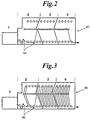
- Bonding and annealing of the trilayer precursor may be performed in a multizone oven 40, each zone capable of maintaining a distinct temperature. See, for example, Figures 2-3.
- Bonding is for joining together the polypropylene-polyethylene-polypropylene precursors to form the trilayer precursor.
- the interply adhesion should be at least 196.85 g/m (5 gram/inch).
- Bonding may be performed at a temperature ranging from 125-135°C and between nip rollers.
- bonding is performed at a temperature ranging from 128-130°C.
- Annealing is to form crystal structures in the polymers to facilitate pore formation in the stretching step. Annealing is influenced by temperature and time.
- the multizoned oven capable of maintaining several distinct temperatures may be advantageous.
- Annealing of the trilayer precursor should be conducted within the temperature range of 105-135°C, preferably in the range of 110-130°C. If annealing is conducted at a single temperature, that temperature should be in the range of 125-132°C, preferably about 128°C.
- annealing is conducted at more than a single temperature, e.g., to separately influence annealing in the differing polymer layers, then the higher temperature, e.g., the temperature influencing the polypropylene, should be in the range of 125-132°C, preferably 128-132°C; and the lower temperature, e.g., the temperature influencing the polyethylene, should be in the range of 105-125°C, preferably about 110°C.
- Stretching the bonded and annealed trilayer precursor forms the microporous structure of battery separators.
- Stretching generally includes several steps, e.g., a cold drawing step, a hot drawing step, and a relax or heat-treating step.
- the relax or heat-treating step is to reduce internal stress within the separator and may be accomplished with either negative draw ratio or substantially no draw tension at various heat profiles.
- Stretching is a continuous process performed in ovens containing a draw frame.
- the cold drawing step is conducted at ambient temperature (i.e., no energy is input into the precursor) and at a draw ratio in the range of 15-40%.
- the draw ratio is in the rang of 20-35%.
- the hot drawing step is conducted at temperatures ranging from 110-125°C and at draw ratios ranging from 105-130%.
- hot drawing is conducted at temperatures ranging from 115-123°C and at draw ratios ranging from 110-125%.
- the relax or heat-treating step is conducted at temperatures ranging from 110-125°C and at draw ratios ranging from -30 to -50%.
- relax or heat-treatment is conducted at temperatures ranging from 115-123°C and at draw ratios of -30 to -50%.
- the trilayer battery separators are wound up and slit to desired widths.
- Gurley ASTM-D726(B) Gurley is a resistance to air flow measured by the Gurley Densometer (e.g. Model 4120). Gurley is the time in seconds required to pass 10ml of air through 6.45 cm 2 (one square inch) of product under a pressure of 30.988 cm (12.2 inches) of water. Thickness Method: T411 om-83 developed under the auspices of the Technical Association of the Pulp and Paper Industry. Thickness is determined using a precision micrometer with a 1.27cm (1/2 inch) diameter, circular shoe contacting the sample at 48.26 kPa (seven (7) PSt). Ten (10) individual micrometer readings taken across the width of the sample are averaged.
- a Mitech Stevens LFRA Texture Analyzer is used. The needle is 1.65 mm in diameter with 0.5 mm radius. The rate of descent is 2 mm/sec and the amount of deflection is 6 mm. The film is held tight in the clamping device with a central hole of 11.3 mm. The displacement (in mm) of the film that was pierced by the needle was recorded against the resistance force (in gram force) developed by the tested film. The maximum resistance force is the puncture strength. Peel Strength Peel strength is measured using a tension and compression tester to determine the force in grams required to separate two 2.54 cm (one-inch) wide sections of bonded membrane.
- the polyethylene precursor was extruded from Fina HDPE 7208 resin to form a 0.38 ⁇ m thick film.
- the polypropylene precursor was extruded from Escorene PP 4292 to form a 0.37 ⁇ m thick film.
- the trilayer precursor was formed as shown in Figure 1.
- the bonding and annealing of the precursor was accomplished as follows: the precursor was strung-up with the oven configured as shown in Figure 2; the oven has 4 zones. The nip rollers 50 are located in zone 2. Zones 2, 3 and 4 were set at a temperature of 128°C and the line speed was 9.144 m/min (30 ft./min). The adhesion of the trilayer precursor was 244.409 g/m (5.7 g/in). The trilayer precursor was then stretched under various conditions (note Table 1) to yield the battery separator, the results are set forth in Table I. Sample Oven Temp (°C) Cold Stretch (%) Hot Stretch (%) Relax (-%) Gurley (Sec) Thickness ⁇ m (mil) Punct.
- the polyethylene precursor was extruded from Fina HDPE 7208 resin to form a 0.38 ⁇ m film.
- the polypropylene precursor was extruded from Escorene PP 4292 to form a 0.37 ⁇ m film.
- the trilayer precursor was formed as shown in Figure 1.
- the bonding and annealing of the precursor was accomplished as follows: the precursor was strung-up with the oven configured as shown in Figure 3. Zone 1 is at ambient temperature, zone 2 at 128-130°C, and zones 3 and 4 at 110°C.
- the line speed was 12.192 m/min (40 ft./min).
- the interply adhesion for the precursor was greater than 1181.102 g/m (30 g/in).
- the trilayer precursors were then stretched under various conditions (note Table 2) and at speeds ranging from 6.096-9.144 m/min (20-30 ft/min). (feed speed) to 12.192-18.288 m/min (40-60 ft/min). (output speed) to yield the battery separator; the results are set forth in Table 2.
- Example 2 The polyethylene precursor was extruded from Hizex HDPE 5202 B resin to form a 0.65 ⁇ m film. Otherwise, the procedures of Example 2 were followed except as noted in Table 3. Sample Oven Temp (°C) Hot Stretch (%) Cold Stretch (%) Relax (-%) Gurley (Sec) Thickness ⁇ m (mil) Shrinkage (%) 1 118 35 115 40 31.6 31.496 (1.24) 10 2 118 35 115 50 33.8 31.496 (1.24) 7.4
Landscapes
- Chemical & Material Sciences (AREA)
- Chemical Kinetics & Catalysis (AREA)
- Electrochemistry (AREA)
- General Chemical & Material Sciences (AREA)
- Cell Separators (AREA)
- Extrusion Moulding Of Plastics Or The Like (AREA)
- Shaping By String And By Release Of Stress In Plastics And The Like (AREA)
- Laminated Bodies (AREA)
Claims (10)
- Verfahren zur Herstellung eines dreischichtigen Batterie-Abschaltseparators, umfassend die Schritte des:Extrudierens einer Polyethylen-Vorstufe,Extrudierens einer Polypropylen-Vorstufe,Bildens einer dreischichtigen Vorstufe, wobei die dreischichtige Vorstufe die Polyethylen-Vorstufe zwischen den beiden Polypropylen-Vorstufen angeordnet enthält,gleichzeitigen Verbindens und Spannungsfreimachens der dreischichtigen Vorstufe unter Bildung einer verbundenen und spannungsfrei gemachten dreischichtigen Vorstufe, wobei das Spannungsfreimachen bei einer von 105 bis 135 °C reichenden Temperatur erfolgt und das Spannungsfreimachen weiterhin zwei Zonen, jede Zone bei einer anderen Temperatur, umfasst,Streckens der verbundenen und spannungsfrei gemachten dreistufigen Vorstufe durch ein Kaltstrecken und ein Heißstrecken, wobei das Kaltstrecken im Bereich von 15 - 40 % erfolgt, und dadurch desBildens des Batterieseparators.
- Verfahren nach Anspruch 1, wobei das Verbinden bei einer von 125 bis 135 °C reichenden Temperatur erfolgt.
- Verfahren nach Anspruch 1, wobei das Verbinden mittels Presswalzen erfolgt.
- Verfahren nach Anspruch 1, wobei das Strecken in mehreren Schritten erfolgt.
- Verfahren zur Herstellung eines dreischichtigen Batterie-Abschaltseparators, umfassend die Schritte des:Extrudierens einer Polyethylen-Vorstufe,Extrudierens einer Polypropylen-Vorstufe,Bildens einer dreischichtigen Vorstufe, wobei die dreischichtige Vorstufe die Polyethylen-Vorstufe zwischen den beiden Polypropylen-Vorstufen angeordnet enthält,Verbindens der dreischichtigen Vorstufe unter Bildung einer verbundenen dreischichtigen Vorstufe,Spannungsfreimachens der dreischichtigen Vorstufe, wobei das Spannungsfreimachen bei einer von 105 bis 135 °C reichenden Temperatur erfolgt, wodurch eine verbundene, spannungsfrei gemachte dreischichtige Vorstufe gebildet wird, wobei das Spannungsfreimachen weiterhin zwei Zonen, jede Zone bei einer anderen Temperatur, umfasst,Streckens der verbundenen, spannungsfrei gemachten dreistufigen Vorstufe durch ein Kaltstrecken und ein Heißstrecken, wobei das Kaltstrecken im Bereich von 15 - 40 % erfolgt, und dadurch desBildens des Batterieseparators.
- Verfahren nach Anspruch 5, wobei das Verbinden bei einer von 125 bis 135 °C reichenden Temperatur erfolgt.
- Verfahren nach Anspruch 5, wobei das Verbinden mittels Presswalzen erfolgt.
- Verfahren nach Anspruch 5, wobei das Verbinden und das Spannungsfreimachen gleichzeitig initiiert werden.
- Verfahren nach Anspruch 5, wobei das Strecken in mehreren Schritten erfolgt.
- Verfahren zur Herstellung eines dreischichtigen Batterie-Abschaltseparators, umfassend die Schritte des:Extrudierens einer Polyethylen-Vorstufe,Extrudierens einer Polypropylen-Vorstufe,Bildens einer dreischichtigen Vorstufe, wobei die dreischichtige Vorstufe die Polyethylen-Vorstufe zwischen den beiden Polypropylen-Vorstufen angeordnet enthält,Verbindens, Spannungsfreimachens und Streckens der dreischichtigen Vorstufe in einem Mehrzonenofen, wobei das Spannungsfreimachen bei einer von 105 bis 135 °C reichenden Temperatur erfolgt und weiterhin zwei Zonen, jede Zone bei einer anderen Temperatur, mit einem Kaltstrecken und einem Heißstrecken umfasst, wobei das Kaltstrecken im Bereich von 15 - 40 % erfolgt, und dadurch desBildens des Batterieseparators.
Applications Claiming Priority (2)
| Application Number | Priority Date | Filing Date | Title |
|---|---|---|---|
| US08/839,664 US5952120A (en) | 1997-04-15 | 1997-04-15 | Method of making a trilayer battery separator |
| US839664 | 2001-04-19 |
Publications (3)
| Publication Number | Publication Date |
|---|---|
| EP0872900A2 EP0872900A2 (de) | 1998-10-21 |
| EP0872900A3 EP0872900A3 (de) | 2000-07-26 |
| EP0872900B1 true EP0872900B1 (de) | 2004-09-29 |
Family
ID=25280352
Family Applications (1)
| Application Number | Title | Priority Date | Filing Date |
|---|---|---|---|
| EP98106208A Expired - Lifetime EP0872900B1 (de) | 1997-04-15 | 1998-04-04 | Verfahren zum Herstellung eines dreilagigen mikroporösen Batterieseparators |
Country Status (7)
| Country | Link |
|---|---|
| US (1) | US5952120A (de) |
| EP (1) | EP0872900B1 (de) |
| JP (1) | JP4247340B2 (de) |
| KR (1) | KR100512540B1 (de) |
| CA (1) | CA2233052A1 (de) |
| DE (1) | DE69826552T2 (de) |
| TW (1) | TW367632B (de) |
Families Citing this family (58)
| Publication number | Priority date | Publication date | Assignee | Title |
|---|---|---|---|---|
| US6180280B1 (en) * | 1998-03-12 | 2001-01-30 | Celgard Inc. | Trilayer battery separator |
| US6080507A (en) * | 1998-04-13 | 2000-06-27 | Celgard Inc. | Trilayer battery separator |
| US6753114B2 (en) * | 1998-04-20 | 2004-06-22 | Electrovaya Inc. | Composite electrolyte for a rechargeable lithium battery |
| US6368742B2 (en) * | 1998-06-26 | 2002-04-09 | Celgard, Inc. | Polypropylene microporous membrane for battery separator |
| KR100349601B1 (ko) * | 1998-12-17 | 2002-10-19 | 주식회사 엘지화학 | 미세 기공막 및 그의 제조 방법_ |
| JP2004500686A (ja) | 1999-12-09 | 2004-01-08 | 日本特殊陶業株式会社 | リチウムイオン電池用セパレータ及び/又はリチウムイオンポリマー電池 |
| US20020136945A1 (en) * | 2000-01-18 | 2002-09-26 | Call Ronald W. | Multilayer battery separators |
| US6432586B1 (en) | 2000-04-10 | 2002-08-13 | Celgard Inc. | Separator for a high energy rechargeable lithium battery |
| US6921608B2 (en) * | 2000-07-11 | 2005-07-26 | Celgard, Inc. | Battery separator |
| US7063917B2 (en) | 2001-02-21 | 2006-06-20 | Ahlstrom Mount Holly Springs, Llc | Laminated battery separator material |
| US6881515B2 (en) * | 2001-05-08 | 2005-04-19 | Celgard Inc. | Separator for polymer battery |
| US8007940B2 (en) * | 2001-12-11 | 2011-08-30 | Eveready Battery Company, Inc. | High discharge capacity lithium battery |
| US20050112462A1 (en) | 2003-11-21 | 2005-05-26 | Marple Jack W. | High discharge capacity lithium battery |
| US6878226B2 (en) * | 2002-01-08 | 2005-04-12 | Wei-Ching Yu | Continuous methods of making microporous battery separators |
| US20040241550A1 (en) * | 2003-05-28 | 2004-12-02 | Wensley C. Glen | Battery separator for lithium polymer battery |
| US7087343B2 (en) * | 2003-07-15 | 2006-08-08 | Celgard, Inc. | High melt integrity battery separator for lithium ion batteries |
| US20050031943A1 (en) * | 2003-08-07 | 2005-02-10 | Call Ronald W. | Battery separator and method of making same |
| US8124274B2 (en) * | 2003-11-21 | 2012-02-28 | Eveready Battery Company, Inc. | High discharge capacity lithium battery |
| US8283071B2 (en) | 2003-11-21 | 2012-10-09 | Eveready Battery Company, Inc. | High discharge capacity lithium battery |
| US20050233214A1 (en) * | 2003-11-21 | 2005-10-20 | Marple Jack W | High discharge capacity lithium battery |
| US20050287425A1 (en) * | 2004-06-25 | 2005-12-29 | Celgard Inc. | Li/MnO2 battery separators with selective ion transport |
| US8945753B2 (en) * | 2005-01-26 | 2015-02-03 | Medtronic, Inc. | Implantable battery having thermal shutdown separator |
| US20070238017A1 (en) * | 2006-04-07 | 2007-10-11 | Celgard Llc | Multilayer separator exhibiting improved strength and stability |
| US8722231B2 (en) * | 2006-11-14 | 2014-05-13 | Mp Assets Corporation | Smart battery separators |
| US10003058B2 (en) * | 2006-11-17 | 2018-06-19 | Celgard, Llc | Method of making a co-extruded, multi-layered battery separator |
| SG183009A1 (en) * | 2007-09-28 | 2012-08-30 | Eveready Battery Inc | Processes for producing synthetic pyrite |
| JP5502707B2 (ja) * | 2009-11-20 | 2014-05-28 | 三菱樹脂株式会社 | 積層多孔フィルム、電池用セパレータおよび電池 |
| KR101861212B1 (ko) | 2010-09-09 | 2018-06-29 | 캘리포니아 인스티튜트 오브 테크놀로지 | 전기화학적 에너지 저장 시스템 및 방법 |
| US9379368B2 (en) | 2011-07-11 | 2016-06-28 | California Institute Of Technology | Electrochemical systems with electronically conductive layers |
| EP2732487A4 (de) | 2011-07-11 | 2015-04-08 | California Inst Of Techn | Neue separatoren für elektrochemische systeme |
| TW201351758A (zh) | 2012-06-11 | 2013-12-16 | Enerage Inc | 電化學裝置隔離膜及其製備方法 |
| CN102729532B (zh) * | 2012-06-11 | 2015-07-01 | 达尼特材料科技(芜湖)有限公司 | 多层多孔膜及其制备方法 |
| KR20210029294A (ko) | 2013-03-15 | 2021-03-15 | 셀가드 엘엘씨 | 리튬 이온 이차 전지용 다층 하이브리드 전지 분리기 및 이의 제조방법 |
| WO2014147648A1 (en) | 2013-03-19 | 2014-09-25 | Council Of Scientic & Industrial Reserach | High-ionic conductivity electrolyte compositions comprising semi-interpenetrating polymer networks and their composites |
| US9680143B2 (en) | 2013-10-18 | 2017-06-13 | Miltec Uv International Llc | Polymer-bound ceramic particle battery separator coating |
| WO2015074037A2 (en) | 2013-11-18 | 2015-05-21 | California Institute Of Technology | Separator enclosures for electrodes and electrochemical cells |
| US10714724B2 (en) | 2013-11-18 | 2020-07-14 | California Institute Of Technology | Membranes for electrochemical cells |
| CN104085101B (zh) * | 2014-07-02 | 2016-06-29 | 湖南锂顺能源科技有限公司 | 一种电池隔膜单向拉伸微孔成型设备 |
| JP2017527093A (ja) | 2014-07-18 | 2017-09-14 | ミルテック ユーヴィー インターナショナル,エルエルシーMiltec Uv International, Llc | セラミック粒子がuvまたはeb硬化ポリマー結合されたリチウム二次電池セパレーター、その生産方法 |
| CN104262674B (zh) * | 2014-08-26 | 2018-02-13 | 东莞新能源科技有限公司 | 多孔复合隔离膜的制备方法 |
| JP6659214B2 (ja) * | 2014-10-17 | 2020-03-04 | トヨタ自動車株式会社 | 電池用セパレータ、積層セパレータ、リチウムイオン二次電池および組電池 |
| CN114122621B (zh) | 2015-06-03 | 2024-08-20 | 赛尔格有限责任公司 | 低电阻抗微孔膜、电池隔板、电池单元、电池及相关方法 |
| EP4148892A1 (de) | 2015-07-31 | 2023-03-15 | Celgard, LLC | Laminierte mehrschichtmembranen, separatoren, batterien und verfahren |
| JP7156942B2 (ja) | 2015-09-18 | 2022-10-19 | セルガード エルエルシー | 改良された膜、カレンダー加工された微多孔膜、電池セパレータ、および関連する方法 |
| CN105489813B (zh) * | 2015-11-03 | 2018-08-03 | 深圳市星源材质科技股份有限公司 | 一种针对干法锂电隔膜的热处理方法 |
| US10340528B2 (en) | 2015-12-02 | 2019-07-02 | California Institute Of Technology | Three-dimensional ion transport networks and current collectors for electrochemical cells |
| CN105470434A (zh) * | 2015-12-17 | 2016-04-06 | 江门市龙世纪科技股份有限公司 | 吹膜法单向拉伸生产pp、pe复合结构隔膜的制备方法 |
| US10677587B2 (en) * | 2016-01-29 | 2020-06-09 | Sumitomo Chemical Company, Limited | Method for measuring curl in separator, slit device, and curl measurement device |
| CN106229444A (zh) * | 2016-07-21 | 2016-12-14 | 昆明云天化纽米科技有限公司 | 一种耐压三层复合结构聚丙烯微孔膜 |
| KR102542572B1 (ko) | 2016-11-11 | 2023-06-13 | 셀가드 엘엘씨 | 개선된 마이크로층 멤브레인, 개선된 전지 세퍼레이터 및 관련 방법 |
| US11027040B2 (en) | 2016-12-29 | 2021-06-08 | Industrial Technology Research Institute | Method for manufacturing a porous film, porous film and method for tissue adhesion |
| US12603321B2 (en) * | 2017-03-20 | 2026-04-14 | Celgard, Llc | Battery separators, electrodes, cells, lithium batteries and related methods |
| WO2019089897A1 (en) * | 2017-11-03 | 2019-05-09 | Celgard, Llc | Improved microporus membranes, battery separators, batteries, and devices having the same |
| CN114128029A (zh) | 2019-05-24 | 2022-03-01 | 赛尔格有限责任公司 | 改进的带涂层的电池隔板及电池 |
| CN111098533B (zh) * | 2019-12-31 | 2022-06-10 | 武汉中兴创新材料技术有限公司 | 一种硬弹性聚丙烯膜的制备方法、硬弹性聚丙烯膜及应用 |
| JP7856579B2 (ja) | 2020-04-17 | 2026-05-11 | セルガード エルエルシー | 非対称多孔質膜 |
| KR102542382B1 (ko) * | 2021-05-18 | 2023-06-13 | 유펙스(주) | 연속공정을 이용한 건식분리막 제조장치 |
| DE102021211933B4 (de) | 2021-10-22 | 2025-09-11 | Powerco Se | Separator für eine Lithium-Ionen-Batteriezelle |
Family Cites Families (9)
| Publication number | Priority date | Publication date | Assignee | Title |
|---|---|---|---|---|
| US4650730A (en) * | 1985-05-16 | 1987-03-17 | W. R. Grace & Co. | Battery separator |
| JPH0698395A (ja) * | 1991-09-30 | 1994-04-08 | Iwatsu Electric Co Ltd | 音源用振動板 |
| US5281491A (en) * | 1991-12-20 | 1994-01-25 | W. R. Grace & Co. | Battery separator |
| US5240655A (en) * | 1991-12-20 | 1993-08-31 | W. R. Grace & Co.-Conn. | Process of making a battery separator |
| JPH0698394A (ja) * | 1992-09-11 | 1994-04-08 | Pioneer Cone Corp | スピーカ用振動部品の製造方法 |
| KR100242363B1 (ko) * | 1994-05-12 | 2000-02-01 | 나카히로 마오미 | 다공성 다층 필름 |
| TW297171B (de) * | 1994-12-20 | 1997-02-01 | Hoechst Celanese Corp | |
| JPH08244152A (ja) * | 1995-03-15 | 1996-09-24 | Nitto Denko Corp | 多孔質フィルムおよびその製造法 |
| JP3939778B2 (ja) * | 1996-02-09 | 2007-07-04 | 日東電工株式会社 | 電池用セパレータ |
-
1997
- 1997-04-15 US US08/839,664 patent/US5952120A/en not_active Expired - Lifetime
-
1998
- 1998-03-25 CA CA002233052A patent/CA2233052A1/en not_active Abandoned
- 1998-04-01 TW TW087104866A patent/TW367632B/zh not_active IP Right Cessation
- 1998-04-04 EP EP98106208A patent/EP0872900B1/de not_active Expired - Lifetime
- 1998-04-04 DE DE69826552T patent/DE69826552T2/de not_active Expired - Fee Related
- 1998-04-09 KR KR10-1998-0012581A patent/KR100512540B1/ko not_active Expired - Lifetime
- 1998-04-14 JP JP10229998A patent/JP4247340B2/ja not_active Expired - Lifetime
Also Published As
| Publication number | Publication date |
|---|---|
| DE69826552T2 (de) | 2005-10-06 |
| DE69826552D1 (de) | 2004-11-04 |
| US5952120A (en) | 1999-09-14 |
| JP4247340B2 (ja) | 2009-04-02 |
| EP0872900A3 (de) | 2000-07-26 |
| EP0872900A2 (de) | 1998-10-21 |
| JPH10289703A (ja) | 1998-10-27 |
| CA2233052A1 (en) | 1998-10-15 |
| KR19980081232A (ko) | 1998-11-25 |
| TW367632B (en) | 1999-08-21 |
| KR100512540B1 (ko) | 2005-11-22 |
Similar Documents
| Publication | Publication Date | Title |
|---|---|---|
| US5952120A (en) | Method of making a trilayer battery separator | |
| EP0718901B1 (de) | Dreilagiger, mikroporöser Batterieseparator | |
| US6602593B1 (en) | Battery separators with reduced splitting propensity | |
| US11731407B2 (en) | Low electrical resistance microporous battery separator membranes, separators, cells, batteries, and related methods | |
| KR100637971B1 (ko) | 배터리 격리판 및 이의 제조방법 | |
| US9908317B2 (en) | Multilayer battery separators | |
| JP6257228B2 (ja) | 電池セパレーター用のミクロポーラス多層膜の製造方法 | |
| EP0715364B1 (de) | Zweilagiger Batterieseparator mit Shutdown-Charakteristik | |
| EP0682376B1 (de) | Poröser mehrschichtiger Film | |
| EP0723304A2 (de) | Verfahren zur Herstellung von mikropöroser kreuzweise geschichteter Batterieseparatormembrane und so hergestellte Batterieseparatoren | |
| JP3852492B2 (ja) | 電池用セパレータの製造法 | |
| EP0924780B1 (de) | Fünflagiger Batterieseparator | |
| JP3436055B2 (ja) | 電池用セパレータ |
Legal Events
| Date | Code | Title | Description |
|---|---|---|---|
| PUAI | Public reference made under article 153(3) epc to a published international application that has entered the european phase |
Free format text: ORIGINAL CODE: 0009012 |
|
| AK | Designated contracting states |
Kind code of ref document: A2 Designated state(s): DE FR GB IT |
|
| AX | Request for extension of the european patent |
Free format text: AL;LT;LV;MK;RO;SI |
|
| PUAL | Search report despatched |
Free format text: ORIGINAL CODE: 0009013 |
|
| RAP1 | Party data changed (applicant data changed or rights of an application transferred) |
Owner name: CELGARD INC. |
|
| AK | Designated contracting states |
Kind code of ref document: A3 Designated state(s): AT BE CH DE DK ES FI FR GB GR IE IT LI LU MC NL PT SE |
|
| AX | Request for extension of the european patent |
Free format text: AL;LT;LV;MK;RO;SI |
|
| 17P | Request for examination filed |
Effective date: 20001013 |
|
| AKX | Designation fees paid |
Free format text: DE FR GB IT |
|
| 17Q | First examination report despatched |
Effective date: 20010403 |
|
| GRAP | Despatch of communication of intention to grant a patent |
Free format text: ORIGINAL CODE: EPIDOSNIGR1 |
|
| GRAS | Grant fee paid |
Free format text: ORIGINAL CODE: EPIDOSNIGR3 |
|
| GRAA | (expected) grant |
Free format text: ORIGINAL CODE: 0009210 |
|
| AK | Designated contracting states |
Kind code of ref document: B1 Designated state(s): DE FR GB IT |
|
| REG | Reference to a national code |
Ref country code: GB Ref legal event code: FG4D |
|
| REF | Corresponds to: |
Ref document number: 69826552 Country of ref document: DE Date of ref document: 20041104 Kind code of ref document: P |
|
| PGFP | Annual fee paid to national office [announced via postgrant information from national office to epo] |
Ref country code: GB Payment date: 20050314 Year of fee payment: 8 |
|
| PGFP | Annual fee paid to national office [announced via postgrant information from national office to epo] |
Ref country code: FR Payment date: 20050401 Year of fee payment: 8 |
|
| PGFP | Annual fee paid to national office [announced via postgrant information from national office to epo] |
Ref country code: DE Payment date: 20050429 Year of fee payment: 8 |
|
| PLBE | No opposition filed within time limit |
Free format text: ORIGINAL CODE: 0009261 |
|
| STAA | Information on the status of an ep patent application or granted ep patent |
Free format text: STATUS: NO OPPOSITION FILED WITHIN TIME LIMIT |
|
| ET | Fr: translation filed | ||
| 26N | No opposition filed |
Effective date: 20050630 |
|
| PG25 | Lapsed in a contracting state [announced via postgrant information from national office to epo] |
Ref country code: GB Free format text: LAPSE BECAUSE OF NON-PAYMENT OF DUE FEES Effective date: 20060404 |
|
| PGFP | Annual fee paid to national office [announced via postgrant information from national office to epo] |
Ref country code: IT Payment date: 20060430 Year of fee payment: 9 |
|
| PG25 | Lapsed in a contracting state [announced via postgrant information from national office to epo] |
Ref country code: DE Free format text: LAPSE BECAUSE OF NON-PAYMENT OF DUE FEES Effective date: 20061101 |
|
| GBPC | Gb: european patent ceased through non-payment of renewal fee |
Effective date: 20060404 |
|
| REG | Reference to a national code |
Ref country code: FR Ref legal event code: ST Effective date: 20061230 |
|
| PG25 | Lapsed in a contracting state [announced via postgrant information from national office to epo] |
Ref country code: FR Free format text: LAPSE BECAUSE OF NON-PAYMENT OF DUE FEES Effective date: 20060502 |
|
| PG25 | Lapsed in a contracting state [announced via postgrant information from national office to epo] |
Ref country code: IT Free format text: LAPSE BECAUSE OF NON-PAYMENT OF DUE FEES Effective date: 20070404 |