EP0873667B1 - Akustisches system - Google Patents
Akustisches system Download PDFInfo
- Publication number
- EP0873667B1 EP0873667B1 EP97903924A EP97903924A EP0873667B1 EP 0873667 B1 EP0873667 B1 EP 0873667B1 EP 97903924 A EP97903924 A EP 97903924A EP 97903924 A EP97903924 A EP 97903924A EP 0873667 B1 EP0873667 B1 EP 0873667B1
- Authority
- EP
- European Patent Office
- Prior art keywords
- locations
- loudspeakers
- transfer function
- locating
- transfer functions
- Prior art date
- Legal status (The legal status is an assumption and is not a legal conclusion. Google has not performed a legal analysis and makes no representation as to the accuracy of the status listed.)
- Expired - Lifetime
Links
Images














Classifications
-
- H—ELECTRICITY
- H04—ELECTRIC COMMUNICATION TECHNIQUE
- H04S—STEREOPHONIC SYSTEMS
- H04S7/00—Indicating arrangements; Control arrangements, e.g. balance control
- H04S7/30—Control circuits for electronic adaptation of the sound field
- H04S7/307—Frequency adjustment, e.g. tone control
-
- H—ELECTRICITY
- H04—ELECTRIC COMMUNICATION TECHNIQUE
- H04R—LOUDSPEAKERS, MICROPHONES, GRAMOPHONE PICK-UPS OR LIKE ACOUSTIC ELECTROMECHANICAL TRANSDUCERS; ELECTRIC HEARING AIDS; PUBLIC ADDRESS SYSTEMS
- H04R2499/00—Aspects covered by H04R or H04S not otherwise provided for in their subgroups
- H04R2499/10—General applications
- H04R2499/13—Acoustic transducers and sound field adaptation in vehicles
-
- H—ELECTRICITY
- H04—ELECTRIC COMMUNICATION TECHNIQUE
- H04S—STEREOPHONIC SYSTEMS
- H04S3/00—Systems employing more than two channels, e.g. quadraphonic
Definitions
- This invention relates to spatial enhancement in multiple source, for example, multiple loudspeaker, sound systems. It is disclosed in the context of a multiple loudspeaker automobile sound system, but is believed to be useful in other contexts as well.
- US-A-4332979 relates to an electronic environmental acoustic simulator. It discloses a method of measurement of acoustical fields and the functional relationships in audio systems for enhancing sound reproduction.
- US-A-3970788 relates to a system for monaural and stereo compatible multidirectional sound matrixing.
- a method of synthesizing a set of filters comprises locating first and second loudspeakers at first and second locations, respectively, coupling a first component of an audio program to the first loudspeaker to be reproduced thereby, and coupling a second component of the audio program to the second loudspeaker to be reproduced thereby.
- First and second microphones are placed at third and fourth locations, respectively, at which the reproduced first and second audio components are to be heard in order to convert audio impinging upon the first and second microphones into first and second microphone signals, respectively.
- a first set of transfer functions is developed from the first and second components of the audio program and the first and second microphone signals.
- One of the first and second loudspeakers is located at a fifth location different from at least one of the first and second locations at which it is desired to create an image of the one of the first and second loudspeakers.
- the first component is coupled to the first loudspeaker to be reproduced thereby.
- the second component is coupled to the second loudspeaker to be reproduced thereby.
- Third and fourth microphone signals are developed from the first and second components impinging on the first and second microphones, respectively.
- a second set of transfer functions is developed from the first and second components and the third and fourth microphone signals, respectively.
- the set of filters is synthesized from the first and second sets of transfer functions.
- locating the first and second loudspeakers at first and second locations, respectively, and placing first and second microphones at third and fourth locations, respectively, together comprise locating the first and second loudspeakers at first and second locations, respectively, which are non-symmetric with respect to the third and fourth locations, respectively.
- placing first and second microphones at third and fourth locations, respectively comprises providing a dummy head and providing the first and second microphones at about the locations of the left and right pinnae, respectively, of the dummy head.
- locating one of the first and second loudspeakers at a fifth location comprises locating the first and second loudspeakers at fifth and sixth locations, respectively, at which it is desired to create images of the first and second loudspeakers, respectively.
- the fifth and sixth locations are different from both the first and second locations.
- the first transfer function is developed before the second transfer function.
- the second transfer function is developed before the first transfer function.
- locating first and second loudspeakers at first and second locations comprises locating first and second loudspeakers at first and second locations, respectively, within a vehicle passenger compartment.
- locating one of the first and second loudspeakers at a fifth location comprises locating the one of the first and second loudspeakers at a fifth location outside the vehicle passenger compartment.
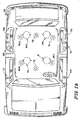
- an automotive sound system 20 accepts the four conventional output signals left front (lf), right front (rf), left rear (lr) and right rear (rr) from an automobile head end 22, which is typically mounted behind a vehicle 21's dashboard 23. These four signals are separately amplified by buffer amplifiers 24, 26, 28, 30, respectively, of conventional configuration.
- the buffered output signals LF, RF, LR, RR are coupled to four input ports of a digital signal processor (DSP) 32 which illustratively is a Motorola 56004 four channel DSP 32.
- DSP 32 can for purposes of this discussion be thought of as a collection of digital filters.
- the functions of these digital filters are to combine and equalize the four channels LF, RF, LR, RR in such ways as to compensate for the head related transfer functions (HRTFs) of four hypothetical passengers sitting in the driver's seat (D), front passenger's seat (FS), left rear passenger's seat (LRS) and right rear passenger's seat (RRS), and for the actual locations of the speakers of the sound system 20.
- Speaker images are formed by the digital filters of DSP 32 at more ideal locations for the listener(s) at one or more of locations D, FS, LRS, RRS.
- the DSP 32 creates an image of a "left" speaker, for example, 30° left and 30 cm (one foot) forward of each left seat hypothetical passenger's left ear, 30° right and 30 cm (one foot) forward of each right seat hypothetical passenger's right ear, and a "right” speaker 30° right and 30cm (one foot) forward of each left seat hypothetical passenger's right ear and 30° left and 30 cm (one foot) forward of each right seat hypothetical passenger's left ear.
- the angles 30° and distance one foot are employed for purposes of illustration only, and are not intended in any way to limit the claims.
- the transfer functions of the DSP 32 filters could equally as readily provide speaker angles of 20° or 45° or some other suitable angles and distances of 15 cm (six inches) or 61 cm (two feet) or some other suitable distances with appropriate modelling. It should also be understood that the image speaker locations need not even be inside the vehicle if placement of the speakers to model the image speaker locations does not interfere with the signal path from the image speaker location to the dummy head(s) which is (are) being used to generate the image speaker locations' transfer functions. The distance and angles need not even be the same for the left and right image speakers for a particular passenger D, FS, LRS, RRS. However for binaural audio, equal angles and distances are conventional.
- the term "hypothetical passenger” is used here to emphasize that the way in which the filters in DSP 32 are synthesized is by modeling using (a) dummy head(s) in the particular make and model of vehicle 21 for which the system 20 is being designed.
- the dummy head(s) is (are) placed at the elevation and in the location the or each passenger, D, FS, LRS and RRS, would occupy in the vehicle 21, and a first transfer function is established from the vehicle sound system 20 for the dummy head(s) at that (those) position(s).
- speakers are placed at the actual locations where it is desired to create the two (L and R) binaural speakers' images for each passenger D, FS, LRS and RRS, and a second transfer function is established for the dummy head at that location with the L and R speakers in their desired or "image" locations.
- a filter which will realize the second transfer function from the first transfer function is then synthesized, using, for example, digital signal processing analogs of the analog signal processing techniques described in, for example, U.S. Patents 4,975,954 and 5,333,200.
- the algorithm for realizing that filter digitally is then programmed into that one channel coupled between that one of the four input ports LF, RF, LR, RR and that one of the four output ports LF', RF', LR', RR' of DSP 32.
- the four output ports LF', RF', LR', RR' are then coupled through separate equalization and filtering channels 50, 52, 54, 56, 58, 60, 62 and 64 to separate suites 66, 68, 70, 72, 74, 76, 78 and 80 respectively, of speakers which reproduce the program material provided to them.
- Channels 50 and 56 each contain a six-pole equalizer 82, 84, respectively, a high pass filter 86, 88, respectively, and a low pass filter 90, 92, respectively, in cascade.
- the corner frequencies of filters 86, 88 illustratively can be 20Hz.
- the corner frequencies of filters 90, 92 illustratively can be 20KHz.
- the poles of equalizers 82, 84 are selected for the particular listening environment of a particular location D, FS, LRS, RRS in a particular make and model of vehicle. These permit distracting, unpleasant, or otherwise undesirable artifacts to be equalized out of the signals supplied to suites 66 and 72, respectively, of speakers.
- Channels 52, 54, 60 and 62 each contain a four-pole equalizer 94, 96, 98 and 100, respectively, and a high pass filter 102, 104, 106 and 108 respectively, in cascade.
- the corner frequencies of filters 102, 104, 106 and 108 illustratively can be 400Hz.
- the poles of equalizers 94, 96, 98 and 100 again are selected for the particular listening environment of a particular location D, FS, LRS, RRS in the particular make and model of vehicle for which system 20 is designed. Again, these permit undesirable artifacts of the operation of system 20 to be equalized out of the signals supplied to suites 68, 70, 76 and 78, respectively, of speakers.
- Channels 58 and 64 each contain a four pole equalizer 110, 112, respectively, a high pass filter 114, 116, respectively, and a low pass filter 118, 120, respectively, in cascade.
- the corner frequencies of filters 114, 116 illustratively can be 50Hz.
- the corner frequencies of filters 118, 120 illustratively can be 400Hz.
- the poles of equalizers 110, 112 also are selected for the particular listening environment of a particular location D, FS, LRS, RRS in the particular make and model of vehicle. These permit undesirable artifacts to be equalized out of the signals supplied to suites 74 and 80, respectively, of speakers.
- An additional channel 122 is formed from the sum of the signals LF, RF, LR, RR at the output terminals of buffer amplifiers 24, 26, 28, 30, respectively.
- This channel 122 includes a summing circuit 124 for summing these signals, a four-pole equalizer 126, high pass filter 128 and low pass filter 130 in cascade.
- the corner frequency of filter 128 illustratively can be 20 Hz.
- the corner frequency of filter 130 illustratively can be 300 Hz.
- the poles of equalizer 126 are selected for the particular listening environment of a particular make and model of vehicle. These permit undesirable artifacts to be equalized out of the signals supplied to a suite 132 of speakers.
- Each channel 50, 52, 54, 56, 58, 60, 62, 64 and 122 includes a voltage controlled amplifier (VCA) 134.
- VCA voltage controlled amplifier
- the control voltage inputs of all of VCAs 134 are coupled to an output port of a frequency-to-voltage converter 150, an input port of which is coupled to a vehicle speed-to-frequency line 152 of the vehicle electrical bus.
- This line when provided, carries pulses at a rate proportional to, for example, vehicle speed. It may be supplied to, and available at, for example, the vehicle speedometer input.
- Each channel 50, 52, 54, 56, 58, 60, 62 and 64 also includes one or more basic power amplifiers 154, each of which has a rated output power of, for example, 40W, into its load.
- suite 132 of speakers includes two, for example, 20 cm diameter subwoofers 156, 158, one mounted in each of the rear doors of the vehicle. Each of these subwoofers 156, 158 is supplied by its own power amplifier 154.
- each of speaker suites 66, 72, 74 and 80 includes a 14 cm or 15 cm diameter midwoofer having a 2 ⁇ voice coil and a 6 ⁇ voice coil with the front speakers (those of suites 66 and 72) mounted in the left and right front kick panels, respectively, and the rear speakers (those of suites 74 and 80) mounted in the left and right rear doors, respectively.
- Each of speaker suites 66, 72, 74 and 80 also illustratively includes a 25 mm dome tweeter mounted in the left front, right front, left rear and right rear door, respectively.
- each of speaker suites 68 and 76 comprises a pair 68-L and 68-R, and 76-L and 76-R, respectively, of 6.5 cm diameter midrange/tweeter speakers mounted in the left and right front headliner (68-L and 68-R, respectively) and the left and right rear headliner (76-L and 76-R, respectively).
- each of speaker suites 70,78 comprises a 6.5 cm diameter midrange/tweeter speaker mounted in the center front headliner and the center rear headliner, respectively.
- the system 20 may be equipped with a dashboard 23-mounted switch control 160 which permits the DSP 32 to be bypassed, should the vehicle 21 operator D wish to do so.
- each of speakers 70, 78 could be split into two separate speakers, one directed more toward the driver or left side passenger and one directed more the right side passenger for a total complement of eight speakers in the headliner (four across the front and four across the rear).
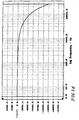
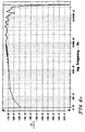
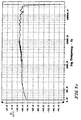
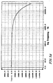
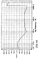
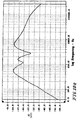
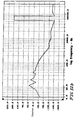
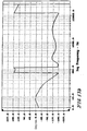
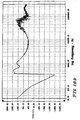
- Fig. 2a illustrates the magnitude of a suitable transfer function of the DSP 32 filter channel between its input port LF and equalizers 82 and 94 for a 1997 BMW 700 series body in dB(volts/volts) versus the logarithm of frequency.
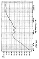
- Fig. 2b illustrates the phase of a suitable transfer function of the DSP 32 filter channel between its input port LF and equalizers 82 and 94 for a 1997 BMW 700 series body in degrees versus the logarithm of frequency.
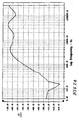
- Fig. 2c illustrates the magnitude of a suitable transfer function of the DSP 32 filter between its input port LF and equalizers 84 and 96 for the above-identified vehicle in dB versus the logarithm of frequency.
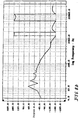
- Fig. 2d illustrates the phase of a suitable transfer function of the DSP 32 filter between its input port LF and equalizers 84 and 96 for the above-identified vehicle in degrees versus the logarithm of frequency.
- Fig. 3a illustrates the magnitude of a suitable transfer function of the DSP 32 filter channel between its input port RF and equalizers 84 and 96 for the above identified vehicle in dB versus the logarithm of frequency.
- Fig. 3b illustrates the phase of a suitable transfer function of the DSP 32 filter channel between its input port RF and equalizers 84 and 96 for the above identified vehicle in degrees versus the logarithm of frequency.
- Fig. 3c illustrates the magnitude of a suitable transfer function of the DSP 32 filter between its input port RF and equalizers 82 and 94 for the above-identified vehicle in dB versus the logarithm of frequency.
- Fig. 3d illustrates the phase of a suitable transfer function of the DSP 32 filter between its input port RF and equalizers 82 and 94 for the above-identified vehicle in degrees versus the logarithm of frequency.
- Fig. 4a illustrates the magnitude of a suitable transfer function of the DSP 32 filter channel between its input port LR and equalizers 98 and 110 for the above identified vehicle in dB versus the logarithm of frequency.
- Fig. 4b illustrates the phase of a suitable transfer function of the DSP 32 filter channel between its input port LR and equalizers 98 and 110 for the above identified vehicle in degrees versus the logarithm of frequency.
- Fig. 4c illustrates the magnitude of a suitable transfer function of the DSP 32 filter between its input port LR and equalizers 100 and 112 for the above-identified vehicle in dB versus the logarithm of frequency.
- Fig. 4d illustrates the phase of a suitable transfer function of the DSP 32 filter between its input port LR and equalizers 100 and 112 for the above-identified vehicle in degrees versus the logarithm of frequency.
- Fig. 5a illustrates the magnitude of a suitable transfer function of the DSP 32 filter channel between its input port RR and equalizers 100 and 112 for the above identified vehicle in dB versus the logarithm of frequency.
- Fig. 5b illustrates the phase of a suitable transfer function of the DSP 32 filter channel between its input port RR and equalizers 100 and 112 for the above identified vehicle in degrees versus the logarithm of frequency.
- Fig. 5c illustrates the magnitude of a suitable transfer function of the DSP 32 filter between its input port RR and equalizers 98 and 110 for the above-identified vehicle in dB versus the logarithm of frequency.
- Fig. 5d illustrates the phase of a suitable transfer function of the DSP 32 filter between its input port RR and equalizers 98 and 110 for the above-identified vehicle in degrees versus the logarithm of frequency.
- Fig. 6a illustrates the magnitude of a suitable transfer function of equalizer 82 for the above identified vehicle in dB versus the logarithm of frequency.
- Fig. 6b illustrates the phase of a suitable transfer function of equalizer 82 for the above identified vehicle in degrees versus the logarithm of frequency.
- Fig. 7a illustrates the magnitude of a suitable transfer function of equalizer 94 for the above identified vehicle in dB versus the logarithm of frequency.
- Fig. 7b illustrates the phase of a suitable transfer function of equalizer 94 for the above identified vehicle in degrees versus the logarithm of frequency.
- Fig. 8a illustrates the magnitude of a suitable transfer function of equalizer 96 for the above identified vehicle in dB versus the logarithm of frequency.
- Fig. 8b illustrates the phase of a suitable transfer function of equalizer 96 for the above identified vehicle in degrees versus the logarithm of frequency.
- Fig. 9a illustrates the magnitude of a suitable transfer function of equalizer 84 for the above identified vehicle in dB versus the logarithm of frequency.
- Fig. 9b illustrates the phase of a suitable transfer function of equalizer 84 for the above identified vehicle in degrees versus the logarithm of frequency.
- Fig. 10a illustrates the magnitude of a suitable transfer function of equalizer 110 for the above identified vehicle in dB versus the logarithm of frequency.
- Fig. 10b illustrates the phase of a suitable transfer function of equalizer 110 for the above identified vehicle in degrees versus the logarithm of frequency.
- Fig. 11a illustrates the magnitude of a suitable transfer function of equalizer 98 for the above identified vehicle in dB versus the logarithm of frequency.
- Fig. 11b illustrates the phase of a suitable transfer function of equalizer 98 for the above identified vehicle in degrees versus the logarithm of frequency.
- Fig. 12a illustrates the magnitude of a suitable transfer function of equalizer 100 for the above identified vehicle in dB versus the logarithm of frequency.
- Fig. 12b illustrates the phase of a suitable transfer function of equalizer 100 for the above identified vehicle in degrees versus the logarithm of frequency.
- Fig. 13a illustrates the magnitude of a suitable transfer function of equalizer 112 for the above identified vehicle in dB versus the logarithm of frequency.
- Fig. 13b illustrates the phase of a suitable transfer function of equalizer 112 for the above identified vehicle in degrees versus the logarithm of frequency.
- Fig. 14a illustrates the magnitude of a suitable transfer function of equalizer 126 for the above identified vehicle in dB versus the logarithm of frequency.
- Fig. 14b illustrates the phase of a suitable transfer function of equalizer 126 for the above identified vehicle in degrees versus the logarithm of frequency.
Landscapes
- Physics & Mathematics (AREA)
- Engineering & Computer Science (AREA)
- Acoustics & Sound (AREA)
- Signal Processing (AREA)
- Stereophonic System (AREA)
- Fittings On The Vehicle Exterior For Carrying Loads, And Devices For Holding Or Mounting Articles (AREA)
- Circuit For Audible Band Transducer (AREA)
Claims (9)
- Verfahren zur Synthese eines Filtersatzes, umfassend die Schritte: Lokalisieren eines ersten und zweiten Lautsprechers (66, 68, 70, 72, 74, 76, 78, 80) an einem ersten bzw. zweiten Ort, Koppeln einer ersten Komponente eines Audioprogramms mit dem ersten Lautsprecher, um dadurch wiedergegeben zu werden, Koppeln einer zweiten Komponente des Audioprogramms mit dem zweiten Lautsprecher, um dadurch wiedergegeben zu werden, Platzieren eines ersten und zweiten Mikrofons an einem dritten bzw. vierten Ort, an welchen die wiedergegebene erste bzw. zweite Audiokomponenten zu hören sein sollen, um auf das erste bzw. zweite Mikrofon auftreffenden Schall in ein erstes bzw. zweites Mikrofonsignal umzuwandeln, Ausbilden eines ersten Satzes von Übertragungsfunktionen aus der ersten und zweiten Komponente des Audioprogramms und dem ersten und zweiten Mikrofonsignal, Lokalisieren eines von dem ersten und zweiten Lautsprecher an einem fünften Ort, der von wenigsten einem von dem ersten und zweiten Ort verschieden ist, an welchem es erwünscht ist, eine Abbildung von einem von dem ersten und zweiten Lautsprecher zu erzeugen, Koppeln der ersten Komponente mit dem ersten Lautsprecher, um dadurch wiedergegeben zu werden, Koppeln der zweiten Komponente mit dem zweiten Lautsprecher, um dadurch wiedergegeben zu werden, Ausbilden eines dritten und vierten Mikrofonsignals aus der auf das erste bzw. zweite Mikrofon auftreffenden ersten bzw. zweiten Komponente, Ausbilden eines zweiten Satzes von Übertragungsfunktionen aus der ersten und zweiten Komponente und dem dritten bzw. vierten Mikrofonsignal, und Synthetisieren des Filtersatzes aus dem ersten und zweiten Satz von Übertragungsfunktionen.
- Verfahren nach Anspruch 1, worin das Lokalisieren des ersten und zweiten Lautsprechers an einem ersten bzw. zweiten Ort und das Platzieren des ersten und zweiten Mikrofons an einem dritten bzw. vierten Ort zusammen das Lokalisieren des ersten und zweiten Lautsprechers an einem ersten bzw. zweiten Ort umfasst, welche nicht-symmetrisch in Bezug auf den dritten bzw. vierten Ort sind.
- Verfahren nach Anspruch 1, worin das Platzieren des ersten und zweiten Mikrofons an einem dritten bzw. vierten Orten das Bereitstellen eines Kunstkopfes und das Bereitstellen des ersten und zweiten Mikrofons an etwa der Stelle der linken bzw. rechten Ohrmuschel des Kunstkopfes umfasst.
- Verfahren nach Anspruch 1, worin das Lokalisieren eines von dem ersten und zweiten Lautsprecher an einem fünften Ort das Lokalisieren des ersten und zweiten Lautsprechers an einem fünften bzw. sechsten Ort umfasst, an welchen es erwünscht ist, Abbildungen des ersten bzw. zweiten Lautsprechers zu erzeugen, wobei der fünfte und sechste Ort sowohl von dem ersten als auch von dem zweiten Ort verschieden sind.
- Verfahren nach Anspruch 1, worin das Ausbilden eines ersten Satzes von Übertragungsfunktionen und das Ausbilden eines zweiten Satzes von Übertragungsfunktionen zusammen zuerst das Ausbilden des ersten Satzes von Übertragungsfunktionen und anschließend das Ausbilden des zweiten Satzes von Übertragungsfunktionen umfasst.
- Verfahren nach Anspruch 1, worin das Ausbilden eines ersten Satzes von Übertragungsfunktionen und das Ausbilden eines zweiten Satzes von Übertragungsfunktionen zusammen zuerst das Ausbilden des zweiten Satzes von Übertragungsfunktionen und anschließend das Ausbilden des ersten Satzes von Übertragungsfunktionen umfasst.
- Verfahren nach einem der Ansprüche 1 - 6, worin das Lokalisieren eines ersten und zweiten Lautsprechers an einem ersten bzw. zweiten Ort das Lokalisieren eines ersten und zweiten Lautsprechers an einem ersten bzw. zweiten Ort in einer Fahrzeug-Fahrgastkabine umfasst.
- Verfahren nach Anspruch 7, worin das Lokalisieren eines von dem ersten und zweiten Lautsprecher an einem fünften Ort das Lokalisieren eines von dem ersten und zweiten Lautsprecher an einem fünften Ort außerhalb der Fahrzeug-Fahrgastkabine umfasst.
- Verfahren nach Anspruch 8, worin das Lokalisieren eines von dem ersten und zweiten Lautsprecher an einem fünften Ort das Lokalisieren des ersten und zweiten Lautsprechers an einem fünften bzw. sechsten Ort außerhalb der Fahrzeug-Fahrgastkabine umfasst.
Applications Claiming Priority (3)
| Application Number | Priority Date | Filing Date | Title |
|---|---|---|---|
| US1062996P | 1996-01-26 | 1996-01-26 | |
| US10629P | 1996-01-26 | ||
| PCT/US1997/001054 WO1997027724A1 (en) | 1996-01-26 | 1997-01-24 | Sound system |
Publications (3)
| Publication Number | Publication Date |
|---|---|
| EP0873667A1 EP0873667A1 (de) | 1998-10-28 |
| EP0873667A4 EP0873667A4 (de) | 2000-06-28 |
| EP0873667B1 true EP0873667B1 (de) | 2007-04-11 |
Family
ID=21746630
Family Applications (1)
| Application Number | Title | Priority Date | Filing Date |
|---|---|---|---|
| EP97903924A Expired - Lifetime EP0873667B1 (de) | 1996-01-26 | 1997-01-24 | Akustisches system |
Country Status (8)
| Country | Link |
|---|---|
| US (1) | US5883961A (de) |
| EP (1) | EP0873667B1 (de) |
| JP (1) | JP3519413B2 (de) |
| AU (1) | AU709915B2 (de) |
| BR (1) | BR9707163A (de) |
| CA (1) | CA2240592C (de) |
| DE (1) | DE69737589T2 (de) |
| WO (1) | WO1997027724A1 (de) |
Families Citing this family (14)
| Publication number | Priority date | Publication date | Assignee | Title |
|---|---|---|---|---|
| JP2001028799A (ja) * | 1999-05-10 | 2001-01-30 | Sony Corp | 車載用音響再生装置 |
| DE19958836A1 (de) | 1999-11-29 | 2001-05-31 | Deutsche Telekom Ag | Verfahren und Anordnung zur Verbesserung der Kommunikation in einem Fahrzeug |
| US7424127B1 (en) | 2000-03-21 | 2008-09-09 | Bose Corporation | Headrest surround channel electroacoustical transducing |
| JP4264686B2 (ja) * | 2000-09-14 | 2009-05-20 | ソニー株式会社 | 車載用音響再生装置 |
| US6804565B2 (en) * | 2001-05-07 | 2004-10-12 | Harman International Industries, Incorporated | Data-driven software architecture for digital sound processing and equalization |
| US8139797B2 (en) * | 2002-12-03 | 2012-03-20 | Bose Corporation | Directional electroacoustical transducing |
| US7536019B2 (en) | 2003-12-22 | 2009-05-19 | Lear Corporation | Audio system for use with a vehicle |
| US20060256976A1 (en) * | 2005-05-11 | 2006-11-16 | House William N | Spatial array monitoring system |
| JP2007003957A (ja) * | 2005-06-27 | 2007-01-11 | Matsushita Electric Ind Co Ltd | 車両用通信システム |
| US9088842B2 (en) | 2013-03-13 | 2015-07-21 | Bose Corporation | Grille for electroacoustic transducer |
| US9327628B2 (en) | 2013-05-31 | 2016-05-03 | Bose Corporation | Automobile headrest |
| US9699537B2 (en) | 2014-01-14 | 2017-07-04 | Bose Corporation | Vehicle headrest with speakers |
| EP4207815A1 (de) * | 2021-12-29 | 2023-07-05 | GN Audio A/S | Verfahren und vorrichtung zur verarbeitung von räumlichen audiosignalen |
| JP2024129712A (ja) * | 2023-03-13 | 2024-09-27 | トヨタ自動車株式会社 | 組立体 |
Family Cites Families (21)
| Publication number | Priority date | Publication date | Assignee | Title |
|---|---|---|---|---|
| US3970788A (en) * | 1971-10-06 | 1976-07-20 | Cooper Duane H | Monaural and stereo compatible multidirectional sound matrixing |
| US4132859A (en) * | 1977-12-02 | 1979-01-02 | Egils Ranga | Sound reproducing apparatus |
| US4332979A (en) * | 1978-12-19 | 1982-06-01 | Fischer Mark L | Electronic environmental acoustic simulator |
| JPS5811159B2 (ja) * | 1979-05-18 | 1983-03-01 | 松下電器産業株式会社 | 車載用音響再生装置 |
| AT379275B (de) * | 1982-04-20 | 1985-12-10 | Neutrik Ag | Stereophone wiedergabeanlage in fahrgastraeumen von kraftfahrzeugen |
| US5129004A (en) * | 1984-11-12 | 1992-07-07 | Nissan Motor Company, Limited | Automotive multi-speaker audio system with different timing reproduction of audio sound |
| US4703502A (en) * | 1985-01-28 | 1987-10-27 | Nissan Motor Company, Limited | Stereo signal reproducing system |
| JPS61210800A (ja) * | 1985-03-14 | 1986-09-18 | Nissan Motor Co Ltd | 音響再生装置 |
| CA1279270C (en) * | 1986-07-11 | 1991-01-22 | Matsushita Electric Industrial Co., Ltd. | Sound reproducing apparatus for use in vehicle |
| US4972489A (en) * | 1987-02-19 | 1990-11-20 | Matsushita Electric Industrial Co., Ltd. | Sound reproducing apparatus |
| JPS644200A (en) * | 1987-06-26 | 1989-01-09 | Nissan Motor | Sound field improving device |
| US5034983A (en) * | 1987-10-15 | 1991-07-23 | Cooper Duane H | Head diffraction compensated stereo system |
| US4893342A (en) * | 1987-10-15 | 1990-01-09 | Cooper Duane H | Head diffraction compensated stereo system |
| US5136651A (en) * | 1987-10-15 | 1992-08-04 | Cooper Duane H | Head diffraction compensated stereo system |
| US4910779A (en) * | 1987-10-15 | 1990-03-20 | Cooper Duane H | Head diffraction compensated stereo system with optimal equalization |
| US4975954A (en) * | 1987-10-15 | 1990-12-04 | Cooper Duane H | Head diffraction compensated stereo system with optimal equalization |
| KR910008762B1 (ko) * | 1988-12-07 | 1991-10-19 | 삼성전자 주식회사 | 4채널 서라운드 사운드 발생회로 |
| JPH0623119Y2 (ja) * | 1989-01-24 | 1994-06-15 | パイオニア株式会社 | サラウンド方式ステレオ再生装置 |
| US5172415A (en) * | 1990-06-08 | 1992-12-15 | Fosgate James W | Surround processor |
| JP3006059B2 (ja) * | 1990-09-17 | 2000-02-07 | ソニー株式会社 | 音場拡大装置 |
| US5754664A (en) * | 1993-09-09 | 1998-05-19 | Prince Corporation | Vehicle audio system |
-
1997
- 1997-01-24 US US08/809,211 patent/US5883961A/en not_active Expired - Lifetime
- 1997-01-24 CA CA002240592A patent/CA2240592C/en not_active Expired - Fee Related
- 1997-01-24 EP EP97903924A patent/EP0873667B1/de not_active Expired - Lifetime
- 1997-01-24 AU AU18361/97A patent/AU709915B2/en not_active Ceased
- 1997-01-24 JP JP52698497A patent/JP3519413B2/ja not_active Expired - Fee Related
- 1997-01-24 DE DE69737589T patent/DE69737589T2/de not_active Expired - Lifetime
- 1997-01-24 BR BR9707163A patent/BR9707163A/pt not_active IP Right Cessation
- 1997-01-24 WO PCT/US1997/001054 patent/WO1997027724A1/en not_active Ceased
Also Published As
| Publication number | Publication date |
|---|---|
| DE69737589T2 (de) | 2007-08-09 |
| CA2240592A1 (en) | 1997-07-31 |
| AU1836197A (en) | 1997-08-20 |
| JP2000504886A (ja) | 2000-04-18 |
| CA2240592C (en) | 2003-01-21 |
| US5883961A (en) | 1999-03-16 |
| EP0873667A1 (de) | 1998-10-28 |
| EP0873667A4 (de) | 2000-06-28 |
| WO1997027724A1 (en) | 1997-07-31 |
| JP3519413B2 (ja) | 2004-04-12 |
| BR9707163A (pt) | 1999-05-18 |
| AU709915B2 (en) | 1999-09-09 |
| DE69737589D1 (de) | 2007-05-24 |
Similar Documents
| Publication | Publication Date | Title |
|---|---|---|
| US5754664A (en) | Vehicle audio system | |
| CA2228051C (en) | Acoustic correction apparatus | |
| EP0873667B1 (de) | Akustisches system | |
| EP2806663A1 (de) | Erzeugung von Individuellen Schallzonen innerhalb eines Hörraumes | |
| US5117459A (en) | Ambient imaging loudspeaker system | |
| US20030021433A1 (en) | Speaker configuration and signal processor for stereo sound reproduction for vehicle and vehicle having the same | |
| CN1586091B (zh) | 家庭和汽车听音用的分立式环绕声音响系统 | |
| US4847904A (en) | Ambient imaging loudspeaker system | |
| JP2780997B2 (ja) | 音響システム | |
| EP1021062A2 (de) | Verfahren und Vorrichtung zur Wiedergabe von mehrkanaligen Audiosignalen | |
| EP1280377A1 (de) | Lautsprecheranordnung und Signalprozessor zur Stereotonwiedergabe für ein Fahrzeug und ein diese Anordnung enthaltendes Fahrzeug | |
| US7099480B2 (en) | System for generating sounds | |
| JP2003087900A (ja) | スピーカ装置 | |
| JPH09252500A (ja) | 音響機器におけるステレオ再生方式 | |
| US5594801A (en) | Ambient expansion loudspeaker system | |
| JP2757499B2 (ja) | 車載音響再生装置 | |
| JPH0383492A (ja) | カーオーディオ装置 | |
| JP2572563Y2 (ja) | 非対称音場補正装置 | |
| EP0603970A1 (de) | Schallwiedergabesystem und Einstellungsschaltung zur Anwendung in diesem System | |
| JP2003048490A (ja) | 車載用スピーカ装置 | |
| JPH11355896A (ja) | 音響再生装置 | |
| JP2004168265A (ja) | 車載用スピーカ装置 | |
| JPS63217899A (ja) | 車載用音響再生装置 | |
| JPH0822112B2 (ja) | 音響再生装置 | |
| JP2003054326A (ja) | 車両用ステレオ音響再生のためのスピーカー配置と信号処理機及びこれらを備えた車両 |
Legal Events
| Date | Code | Title | Description |
|---|---|---|---|
| PUAI | Public reference made under article 153(3) epc to a published international application that has entered the european phase |
Free format text: ORIGINAL CODE: 0009012 |
|
| 17P | Request for examination filed |
Effective date: 19980807 |
|
| AK | Designated contracting states |
Kind code of ref document: A1 Designated state(s): DE ES FR GB IT SE |
|
| A4 | Supplementary search report drawn up and despatched |
Effective date: 20000511 |
|
| AK | Designated contracting states |
Kind code of ref document: A4 Designated state(s): DE ES FR GB IT SE |
|
| 17Q | First examination report despatched |
Effective date: 20011008 |
|
| GRAP | Despatch of communication of intention to grant a patent |
Free format text: ORIGINAL CODE: EPIDOSNIGR1 |
|
| GRAS | Grant fee paid |
Free format text: ORIGINAL CODE: EPIDOSNIGR3 |
|
| GRAA | (expected) grant |
Free format text: ORIGINAL CODE: 0009210 |
|
| AK | Designated contracting states |
Kind code of ref document: B1 Designated state(s): DE ES FR GB IT SE |
|
| REG | Reference to a national code |
Ref country code: GB Ref legal event code: FG4D |
|
| REF | Corresponds to: |
Ref document number: 69737589 Country of ref document: DE Date of ref document: 20070524 Kind code of ref document: P |
|
| PG25 | Lapsed in a contracting state [announced via postgrant information from national office to epo] |
Ref country code: SE Free format text: LAPSE BECAUSE OF FAILURE TO SUBMIT A TRANSLATION OF THE DESCRIPTION OR TO PAY THE FEE WITHIN THE PRESCRIBED TIME-LIMIT Effective date: 20070711 |
|
| PG25 | Lapsed in a contracting state [announced via postgrant information from national office to epo] |
Ref country code: ES Free format text: LAPSE BECAUSE OF FAILURE TO SUBMIT A TRANSLATION OF THE DESCRIPTION OR TO PAY THE FEE WITHIN THE PRESCRIBED TIME-LIMIT Effective date: 20070722 |
|
| PLBE | No opposition filed within time limit |
Free format text: ORIGINAL CODE: 0009261 |
|
| STAA | Information on the status of an ep patent application or granted ep patent |
Free format text: STATUS: NO OPPOSITION FILED WITHIN TIME LIMIT |
|
| 26N | No opposition filed |
Effective date: 20080114 |
|
| PGFP | Annual fee paid to national office [announced via postgrant information from national office to epo] |
Ref country code: IT Payment date: 20140124 Year of fee payment: 18 Ref country code: FR Payment date: 20140117 Year of fee payment: 18 |
|
| PGFP | Annual fee paid to national office [announced via postgrant information from national office to epo] |
Ref country code: GB Payment date: 20140127 Year of fee payment: 18 |
|
| GBPC | Gb: european patent ceased through non-payment of renewal fee |
Effective date: 20150124 |
|
| PG25 | Lapsed in a contracting state [announced via postgrant information from national office to epo] |
Ref country code: GB Free format text: LAPSE BECAUSE OF NON-PAYMENT OF DUE FEES Effective date: 20150124 |
|
| REG | Reference to a national code |
Ref country code: FR Ref legal event code: ST Effective date: 20150930 |
|
| PG25 | Lapsed in a contracting state [announced via postgrant information from national office to epo] |
Ref country code: FR Free format text: LAPSE BECAUSE OF NON-PAYMENT OF DUE FEES Effective date: 20150202 |
|
| PG25 | Lapsed in a contracting state [announced via postgrant information from national office to epo] |
Ref country code: IT Free format text: LAPSE BECAUSE OF NON-PAYMENT OF DUE FEES Effective date: 20150124 |
|
| PGFP | Annual fee paid to national office [announced via postgrant information from national office to epo] |
Ref country code: DE Payment date: 20160127 Year of fee payment: 20 |
|
| REG | Reference to a national code |
Ref country code: DE Ref legal event code: R071 Ref document number: 69737589 Country of ref document: DE |