EP0873877A2 - Système de transfert de feuilles avec bande transporteuse et aspirateur - Google Patents
Système de transfert de feuilles avec bande transporteuse et aspirateur Download PDFInfo
- Publication number
- EP0873877A2 EP0873877A2 EP98106977A EP98106977A EP0873877A2 EP 0873877 A2 EP0873877 A2 EP 0873877A2 EP 98106977 A EP98106977 A EP 98106977A EP 98106977 A EP98106977 A EP 98106977A EP 0873877 A2 EP0873877 A2 EP 0873877A2
- Authority
- EP
- European Patent Office
- Prior art keywords
- conveyor belt
- sheet
- transfer system
- downstream side
- attracting force
- Prior art date
- Legal status (The legal status is an assumption and is not a legal conclusion. Google has not performed a legal analysis and makes no representation as to the accuracy of the status listed.)
- Granted
Links
Images



Classifications
-
- B—PERFORMING OPERATIONS; TRANSPORTING
- B65—CONVEYING; PACKING; STORING; HANDLING THIN OR FILAMENTARY MATERIAL
- B65H—HANDLING THIN OR FILAMENTARY MATERIAL, e.g. SHEETS, WEBS, CABLES
- B65H29/00—Delivering or advancing articles from machines; Advancing articles to or into piles
- B65H29/24—Delivering or advancing articles from machines; Advancing articles to or into piles by air blast or suction apparatus
- B65H29/241—Suction devices
- B65H29/242—Suction bands or belts
-
- B—PERFORMING OPERATIONS; TRANSPORTING
- B41—PRINTING; LINING MACHINES; TYPEWRITERS; STAMPS
- B41J—TYPEWRITERS; SELECTIVE PRINTING MECHANISMS, i.e. MECHANISMS PRINTING OTHERWISE THAN FROM A FORME; CORRECTION OF TYPOGRAPHICAL ERRORS
- B41J11/00—Devices or arrangements of selective printing mechanisms, e.g. ink-jet printers or thermal printers, for supporting or handling copy material in sheet or web form
- B41J11/007—Conveyor belts or like feeding devices
-
- B—PERFORMING OPERATIONS; TRANSPORTING
- B41—PRINTING; LINING MACHINES; TYPEWRITERS; STAMPS
- B41J—TYPEWRITERS; SELECTIVE PRINTING MECHANISMS, i.e. MECHANISMS PRINTING OTHERWISE THAN FROM A FORME; CORRECTION OF TYPOGRAPHICAL ERRORS
- B41J11/00—Devices or arrangements of selective printing mechanisms, e.g. ink-jet printers or thermal printers, for supporting or handling copy material in sheet or web form
- B41J11/0085—Using suction for maintaining printing material flat
-
- B—PERFORMING OPERATIONS; TRANSPORTING
- B65—CONVEYING; PACKING; STORING; HANDLING THIN OR FILAMENTARY MATERIAL
- B65H—HANDLING THIN OR FILAMENTARY MATERIAL, e.g. SHEETS, WEBS, CABLES
- B65H2301/00—Handling processes for sheets or webs
- B65H2301/40—Type of handling process
- B65H2301/42—Piling, depiling, handling piles
- B65H2301/421—Forming a pile
- B65H2301/4212—Forming a pile of articles substantially horizontal
Definitions
- This invention relates to a sheet transfer system, and more particularly to a sheet transfer system for transferring sheets, on which an image is recorded by an image forming system such as a printer or a copier, to a tray.
- Figure 9 shows a typical printer.
- a paper supply table 2 is disposed on one side of a printer body 1 and printing papers 3 are stacked on the paper supply table 2.
- the printing papers 3 are taken in the printer body 1 by an intake roller 4 and only the uppermost printing paper in the stack is separated from the stack and fed into the printer body 1 by a pair of separator rollers 5.
- the printing paper 3 thus supplied to the printer body 1 is passed through a resist roller 6 and an ink transfer drum 7, whereby an image is recorded on the printing paper 3 by stencil printing.
- the printing paper 3 bearing thereon a printed image is transferred by a sheet transfer system 8 and discharged to a tray 9 on the other side of the printer body 1.
- the printed paper is generally transferred by use of a vacuum conveyor (a suction belt) not to contact the front side of the printed paper bearing thereon the printed image.
- the vacuum conveyor generally comprises a pair of conveyor belts 8a which extend in parallel to the direction of transfer on opposite sides of the path along which the printed papers are transferred, and a vacuum fan 8b disposed between the conveyor belts 8a below them.
- the vacuum fan 8b When the vacuum fan 8b is operated to generate suction force, the printed paper is attracted against the conveyor belts 8a under the suction force and when the conveyor belts 8a are driven, the printed paper is conveyed and discharged onto the tray 9.
- the vacuum fan 8b is disposed at the middle of the conveyor belts 8a as seen in the longitudinal direction thereof. This is for generating the suction force as uniform as possible over the entire area of the transfer area.
- the suction force is most strong at the middle of the conveyor belts 8a where the vacuum fan 8b is disposed and is gradually reduced toward the ends of the conveyor belts 8a. Further when the area of the part of the printed paper on which the suction force from the vacuum fan 8b acts is reduced, the attracting force (i.e., the paper holding force) is naturally weakened. When the attractinq force is weak, the rotating force of the conveyor belts 8a cannot be efficiently transmitted to the printed paper and the transfer force is weakened.
- the primary object of the present invention is to provide a sheet transfer system which can constantly provide a desired transfer force to the printed paper and surely discharge the printed paper.
- a sheet transfer system for transferring sheets on which an image is recorded by an image forming system and discharging the sheets to a tray, which sheet transfer system comprising a conveyor belt and an attracting force generating means which generates an attracting force for attracting the sheets against the conveyor belt, wherein the improvement comprises that
- the expression "the attracting force is stronger at the downstream side portion of the conveyor belt” means that the attracting force is relatively strong at the downstream side portion as compared with that at the upstream side portion or the central portion.
- the attracting force can be made stronger at the downstream side portion of the conveyor belt by disposing the attracting force generating means on the downstream side of the middle of the conveyor belt as seen in the direction of transfer.
- a plurality of first vacuum holes are formed in the conveyor belt.
- a guide plate is provided below the part of the conveyor belt which contributes to transfer of the sheet and a plurality of second vacuum holes are formed in the guide plate at a part where the second vacuum holes can be aligned with the first vacuum holes as the conveyor belt runs so that the attracting force generated by the attracting force generating means acts on the sheet through the first and second vacuum holes and the effective area which actually contributes to supplying the attracting force to the sheet to be transferred is determined by the area over which the first and second vacuum holes overlap with each other.
- the attracting force can be made stronger at the downstream side portion of the conveyor belt by increasing the area over which the first and second vacuum holes overlap with each other at the downstream side portion of the conveyor belt.
- An air blow means may be provided above the downstream side of the conveyor belt to urge the sheet toward the conveyor belt by the pressure of air blown from the air blow means.
- a plurality of cutaway portions may be formed on a downstream side pulley around which the conveyor belt is passed so that the attracting force can be applied through the cutaway portions.
- the sheet can be still firmly held on the conveyor belt under a desired attracting force, whereby a desired transfer force can be applied to the sheet until it is finally discharged onto the tray.
- the attracting force is weaker at the upstream side end portion than the downstream side end portion, the following problem can be overcome. That is, when a sheet is delivered from an upstream side sheet transfer system to a downstream side sheet transfer system, the sheet once comes to extend over both the transfer systems. In such a case, when the transfer speed of the downstream side sheet transfer system is lower than that of the upstream side transfer system, the central portion of the sheet can be bulged upward due to the difference in the transfer speed since both the leading end portion and the trailing end portion of the sheet are held by the respective transfer systems.
- the sheet holding force of the upstream side transfer system prevails over that of the downstream side transfer system and the sheet can be smoothly delivered to the downstream side transfer system without fear than the sheet is deformed.
- a sheet transfer system 10 in accordance with a first embodiment of the present invention is disposed inside a printer body 1 of a stencil printer.
- the printer shown in Figure 1 is substantially the same as that shown in Figure 9 except the sheet transfer system, and accordingly the elements analogous to those shown in Figure 9 are given the reference numerals.
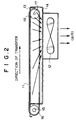
- the sheet transfer system 10 is a vacuum conveyor and basically comprises a pair of conveyor belts 11 which extend in parallel to the direction of transfer of the printed paper on opposite sides of the path along which the printed papers are transferred, and a vacuum fan 12 disposed between the conveyor belts 11 below them. In the sheet transfer system 10, the printed paper is attracted against the conveyor belts 11 under suction generated by the vacuum fan 12.
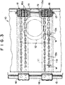
- the vacuum fan 12 is disposed on the downstream side of the middle of the conveyor belts 11 as seen in the direction of transfer. More specifically, as clearly shown in Figures 2 and 3, the vacuum fan 12 is disposed in the downstream side end portion of the sheet transfer system 10. With this arrangement, the suction force is the strongest in the downstream side end portion of the sheet transfer passage above the vacuum fan 12 and the weakest in the upstream side end portion. That is, the suction force is gradually increased from the upstream end toward the downstream end.
- a flat guide plate 13 extends horizontally below the upper run of the conveyor belts 11 substantially over entire area of the sheet transfer system 10.
- a casing 14 which opens upward is mounted on the lower surface of the guide plate 13 in a predetermined position.
- the vacuum fan 12 is mounted on the bottom of the casing 14 at the downstream side end portion of the casing 14.
- the inner space of the casing 14 is communicated with the vacuum fan 12 through an opening formed in the bottom of the casing 14.
- a drive shaft 15 extends horizontally in perpendicular to the direction of transfer on the upstream side of the sheet transfer system 10 and a pair of drive pulleys 16 are mounted on the drive shaft 15 at a predetermined distance from each other.
- the drive shaft 15 is rotated at a predetermined speed by a drive motor (not shown).
- a driven shaft 17 extends horizontally in parallel to the drive shaft 15 inside the casing 14 on the downstream side of the casing 14. Opposite end portions of the driven shaft 17 are supported for rotation on the side walls of the casing 14.
- a pair of driven pulleys 18 are mounted on the driven shaft 17 at a distance from each other. Thus the driven pulleys 18 are disposed inside the casing 14. The distance between the driven pulleys 18 is equal to that between the drive pulleys 16.
- a cutaway portion 13a is formed in the guide plate 13 at a part opposed to each driven pulley 18 and the driven pulley 18 projects outside through the cutaway portion 13a.
- Each conveyor belt 11 is passed around one of the drive pulleys 16 and one of the driven pulleys 18 which are opposed to each other in the direction of transfer.
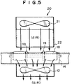
- the shape of the cutaway portion 13a is similar to that shown in Figure 5.
- the drive shaft 15 is rotated, the conveyor belts 11 are run and the driven pulleys 17 are rotated by way of the drive pulleys 16.
- the parts of the conveyor belts 11 which are positioned above the guide plate 13 are able to contact the printed paper and contribute to transfer of the printed paper.
- the upper surface of the guide plate 13 is in contact with the conveyor belts 11 and the part of the upper surface of the guide plate 13 between the conveyor belts 11 supports the printed paper together with the conveyor belts 11.
- Each conveyor belt 11 is provided with a plurality of first vacuum holes 11a which are circular holes of the same diameter and are arranged in two rows at regular intervals.
- the first vacuum holes 11a in one row is shifted from those in the other row in the longitudinal direction of the conveyor belt 11 so that each first vacuum hole 11a in one row is positioned at the middle of adjacent two first vacuum holes 11a in the other row as seen in the transverse direction of the conveyor belt 11.
- a plurality of second vacuum holes 13b are formed in the guide plate 13 at the portion opposed to each conveyor belt 11.
- the second vacuum holes 13b are arranged in two rows in the same manner as the first vacuum holes 11a.
- Each of the second vacuum holes 13b is in the form of a slit extending along the axis of the row of the first vacuum holes 11a.
- the effective area which actually contributes to supplying suction force to the printed paper to be transferred is the overlapping portion of the first and second vacuum holes 11a and 13b.
- the widths of the second vacuum holes 13b differ in the longitudinal direction of the conveyor belts 11. That is, the widths w of the second vacuum holes 13b on the upstream side are smaller than the widths w' of the second vacuum holes 13b on the downstream side. As a result, the suction force acting on the printed paper is larger on the downstream side than on the upstream side.
- the attracting force acting on the printed paper is increased from the upstream side toward the downstream side by shifting the vacuum fan 12 toward the downstream side and making the widths of the second vacuum holes 13a larger on the downstream side than on the upstream side, whereby the printed paper can be surely held until it is discharged to the tray and can be discharged in an optical manner.
- a plurality of cutaway portions 18a are formed in each of the driven pulleys 18.
- Each cutaway portion 18a is in the form of a channel formed around the driven pulley 18. That is, the driven pulley 18 is reduced in diameter at the cutaway portion 18a.
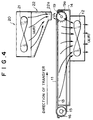
- Reference numeral 19 in Figure 3 denotes a kick roller which has a serrated peripheral edge as shown in Figure 4 and ejects the printed paper toward the tray by pushing the trailing edge of the paper by the serrated peripheral edge thereof.
- Each kick roller 19 is mounted on the driven shaft 17 on the inner side of the driven pulley 18 and a part of the outer peripheral edge of the kick roller 19 projects upward above the conveyor belts 11.
- the effective area which actually contributes to supplying suction force to the printed paper is made to be larger on the downstream side by increasing the widths of the second vacuum holes 13b
- the effective area may be changed in other various manners. For example, it may be changed by changing the number of the second vacuum holes 13a which overlap with the first vacuum holes 11a at one time with the width of the second vacuum holes 13a kept uniform (e.g., by arranging so that one second vacuum hole 13b overlaps with one first vacuum hole 11a on the upstream side and a pair of second vacuum holes 13a overlap with one first vacuum hole 11a), or by changing the density of the second vacuum holes 13b.
- an air blower 20 is provided above the downstream side end portion of the transfer path.
- the air blower 20 comprises a fan 21 and an air guide pipe 22 whose air outlet port 22a is positioned just above the driven pulleys 18.
- air above the fan 21 is taken in and blow over the driven pulleys 18 and the kick rollers 19 through the air outlet port 22a.
- the printed paper on the conveyor belts 11 is pressed against the belts 11 by air blown from above through the air outlet port 22a.
- the air pressure together with the attracting force by the vacuum fan 12 causes the printed paper to surely receive the transfer force until its trailing edge is conveyed to the downstream end.
- the air outlet port 22a is disposed just above the driven pulleys 18 and the kick roller 19, the trailing end portion of the printed paper is bent downward under the air pressure when the trailing end portion comes to the kick rollers 19 and accordingly the teeth 19a of the kick rollers 19 can be surely brought into engagement with the trailing edge of the printed paper, whereby the transfer force by the kick roller 19 can be surely transmitted to the printed paper and the printed paper can be discharged with a desirable transfer force.
- the effective area which actually contributes to supplying suction force to the printed paper may be made to be larger on the downstream side in the manner described above in conjunction with the first embodiment, which is preferable, though not necessary, since the effect of the air blower and the effect of the biased attracting force distribution associate with each other. Further the driven pulleys 18 may be provided with the cutaway portions described above, though not necessary.
- a third embodiment of the present invention will be described with reference to Figures 7A and 7B.
- the sheet transfer system of this embodiment basically the same as that of the second embodiment except that the arrangement of the air blower is simplified. That is, though in the second embodiment, both the vacuum fan 12 and the air blower fan 21 are used, the vacuum fan 12 doubles as the air blower fan 21 in this embodiment, whereby the number of the parts is reduced, the structure is simplified and the overall size of the system is reduced.
- a circulation passage 24 extending from below the vacuum fan 12 to above the conveyor belts 11.
- the circulation passage 24 is disposed, for instance, beside the conveyor belts 11 not to interfere with transfer of the printed paper to the tray 9.
- the upper open end of the circulation passage 24 forms an air outlet port 24a.
- the air outlet port 24a is positioned just above the downstream side end, more particularly just above the driven pulleys 18 and the kick rollers 19.
- the sheet transfer system of the present invention is built in the printer body, the sheet transfer system of the present invention may be employed in other systems.
- the sheet transfer system of the present invention may be incorporated in a sorter 25 which is disposed beside the printer 1 to sort the printed papers discharged from the printer 1.
- the sorter 25 is provided with a plurality of trays or bins 26.
- the trays 26 are moved up and down by an up-and-down mechanism (not shown) and one of the trays 26 is selectively positioned near the sheet outlet port 10a of the sheet transfer system 10.
- the sheet transfer system 10 receives a printed sheet from the printer 1 and transfers the paper onto the tray placed near the sheet outlet port 10a.
- the sorter 25 may be of a known structure.
Landscapes
- Engineering & Computer Science (AREA)
- Mechanical Engineering (AREA)
- Delivering By Means Of Belts And Rollers (AREA)
Applications Claiming Priority (3)
| Application Number | Priority Date | Filing Date | Title |
|---|---|---|---|
| JP11501997 | 1997-04-18 | ||
| JP115019/97 | 1997-04-18 | ||
| JP11501997A JP3662385B2 (ja) | 1997-04-18 | 1997-04-18 | 用紙搬送装置 |
Publications (3)
| Publication Number | Publication Date |
|---|---|
| EP0873877A2 true EP0873877A2 (fr) | 1998-10-28 |
| EP0873877A3 EP0873877A3 (fr) | 1998-11-25 |
| EP0873877B1 EP0873877B1 (fr) | 2001-07-25 |
Family
ID=14652241
Family Applications (1)
| Application Number | Title | Priority Date | Filing Date |
|---|---|---|---|
| EP98106977A Expired - Lifetime EP0873877B1 (fr) | 1997-04-18 | 1998-04-16 | Système de transfert de feuilles avec bande transporteuse et aspirateur |
Country Status (5)
| Country | Link |
|---|---|
| US (1) | US5967510A (fr) |
| EP (1) | EP0873877B1 (fr) |
| JP (1) | JP3662385B2 (fr) |
| CN (1) | CN1122887C (fr) |
| DE (1) | DE69801185T2 (fr) |
Cited By (7)
| Publication number | Priority date | Publication date | Assignee | Title |
|---|---|---|---|---|
| GB2354975B (en) * | 1999-10-05 | 2003-04-02 | Hewlett Packard Co | Belt-type media support for a printer |
| GB2381241A (en) * | 1999-10-05 | 2003-04-30 | Hewlett Packard Co | Printer with vacuum assisted holddown and media transport belt supported by ribbed platen to reduce friction |
| EP0997306B1 (fr) * | 1998-10-30 | 2005-04-13 | Hewlett-Packard Company, A Delaware Corporation | Dispositif de copie sur papier et méthode de sortie des supports d'information |
| EP1905710A2 (fr) | 2006-09-26 | 2008-04-02 | Brother Kogyo Kabushiki Kaisha | Dispositif de transport de feuilles |
| CN101844692A (zh) * | 2009-03-25 | 2010-09-29 | 富士施乐株式会社 | 纸张传送装置和使用该纸张传送装置的图像形成装置 |
| ITMO20100097A1 (it) * | 2010-04-01 | 2011-10-02 | Tecno System S R L | Macchina per la decorazione digitale di piastrelle ceramiche |
| US9004631B1 (en) | 2013-10-31 | 2015-04-14 | Xerox Corporation | Method and apparatus for accumulating excess ink in a stationary receptacle in imaging devices that form images on intermediate imaging surfaces |
Families Citing this family (32)
| Publication number | Priority date | Publication date | Assignee | Title |
|---|---|---|---|---|
| JP2001018512A (ja) * | 1999-07-12 | 2001-01-23 | Riso Kagaku Corp | 用紙搬送装置 |
| US6745685B2 (en) * | 2000-05-17 | 2004-06-08 | Riso Kagaku Corporation | Stencil printing device |
| US6510788B1 (en) * | 2000-05-26 | 2003-01-28 | Perma Press Ab | Device and method for application of coating powder |
| DE10122716A1 (de) * | 2001-05-10 | 2002-11-14 | Baeuerle Gmbh Mathias | Transporteinrichtung für flaches Transportgut, vorzugsweise Papier |
| DE60233689D1 (de) * | 2001-10-17 | 2009-10-22 | Seiko Epson Corp | Transportvorrichtung für Aufzeichnungsmedium und Tintenstrahldrucker |
| US6939001B2 (en) | 2002-10-31 | 2005-09-06 | Hewlett-Packard Development Company, L.P. | Mechanism for passing rigid medium under image-forming mechanism |
| JP4462832B2 (ja) * | 2003-03-07 | 2010-05-12 | セイコーエプソン株式会社 | 記録媒体搬送装置及び記録装置 |
| US7530687B2 (en) * | 2003-03-07 | 2009-05-12 | Seiko Epson Corporation | Medium transporting device for recording apparatus with suction chambers |
| DE10340220A1 (de) * | 2003-09-01 | 2005-04-07 | Pitney Bowes Deutschland Gmbh | Beilagen-Zusammentrageinrichtung, insbesondere für Postbearbeitungsanlagen |
| EP1733892B8 (fr) * | 2004-11-18 | 2011-09-21 | Olympus Corporation | Appareil de traitement de bourrage pour imprimante et procede associe |
| JP4604791B2 (ja) * | 2005-03-25 | 2011-01-05 | 富士ゼロックス株式会社 | 画像形成装置 |
| JP4712588B2 (ja) * | 2006-03-27 | 2011-06-29 | リコーエレメックス株式会社 | 用紙搬送装置、用紙後処理装置、及び画像形成装置 |
| DE102006052302A1 (de) * | 2006-11-03 | 2008-05-08 | Atlantic Zeiser Gmbh | Vorrichtung zum Bedrucken flächiger Teile, insbesondere von Plastik-Karten |
| JP2009062163A (ja) * | 2007-09-07 | 2009-03-26 | Duplo Seiko Corp | 用紙搬送装置 |
| JP2009161342A (ja) * | 2008-01-10 | 2009-07-23 | Seiko I Infotech Inc | 搬送体及び搬送装置 |
| JP4943366B2 (ja) * | 2008-03-31 | 2012-05-30 | 富士フイルム株式会社 | 搬送体及び画像形成装置 |
| JP2011112910A (ja) * | 2009-11-27 | 2011-06-09 | Seiko Epson Corp | 画像形成装置および画像形成方法 |
| JP2011121680A (ja) * | 2009-12-09 | 2011-06-23 | Seiko Epson Corp | 被搬送媒体搬送装置および画像形成装置 |
| US20110141180A1 (en) * | 2009-12-10 | 2011-06-16 | Kabushiki Kaisha Toshiba | Image forming apparatus and method of inkjet having humidity adjustment mechanism |
| US8413794B2 (en) | 2010-07-29 | 2013-04-09 | Xerox Corporation | Variable vacuum belt and plenum for improved media sheet acquisition and transport |
| JP5479278B2 (ja) * | 2010-09-03 | 2014-04-23 | 理想科学工業株式会社 | インクジェット印刷装置 |
| JP5817281B2 (ja) | 2011-07-19 | 2015-11-18 | 株式会社リコー | 画像形成装置 |
| CN102390750B (zh) * | 2011-07-21 | 2013-09-11 | 上海汉铁机械有限公司 | 纸板堆码机吸风计数分单装置 |
| KR101192828B1 (ko) * | 2012-05-11 | 2012-10-18 | 주식회사 에스앤비 | 라미네이팅 장치 및 방법 |
| JP6199790B2 (ja) * | 2014-04-10 | 2017-09-20 | 京セラドキュメントソリューションズ株式会社 | 搬送装置及びインクジェット記録装置 |
| CN105172368A (zh) * | 2015-08-04 | 2015-12-23 | 桂林威迈壁纸有限公司 | 一种防止纸张折叠的入纸装置 |
| US9604813B1 (en) | 2016-03-15 | 2017-03-28 | Xerox Corporation | Dual vacuum belt system with adjustable inter-copy gap |
| US9796546B1 (en) | 2016-07-01 | 2017-10-24 | Xerox Corporation | Vacuum belt system having internal rotary valve |
| US9783373B1 (en) * | 2016-07-12 | 2017-10-10 | Sweed Machinery, Inc. | Veneer transporting apparatus |
| JP6790786B2 (ja) * | 2016-12-13 | 2020-11-25 | 京セラドキュメントソリューションズ株式会社 | シート搬送装置及びそれを備えた画像形成装置 |
| CN110605244A (zh) * | 2019-09-12 | 2019-12-24 | 汕头东风印刷股份有限公司 | 一种产品品质检测装置 |
| CN113697544B (zh) * | 2021-07-28 | 2023-02-28 | 泰安易捷数字印刷有限公司 | 一种纸张负压均匀吸附装置 |
Family Cites Families (9)
| Publication number | Priority date | Publication date | Assignee | Title |
|---|---|---|---|---|
| US4299381A (en) * | 1980-08-04 | 1981-11-10 | Xerox Corporation | Sheet feeding apparatus |
| US4447817A (en) * | 1982-09-27 | 1984-05-08 | Xerox Corporation | Constant velocity copy sheet transport with ink jet printing |
| JPS6019637A (ja) * | 1983-07-12 | 1985-01-31 | Fuji Xerox Co Ltd | 複写機の用紙搬送装置 |
| GB2238759B (en) * | 1989-11-09 | 1994-05-25 | Dataproducts Corp | High accuracy vacuum belt and pinch roller media transport mechanism |
| JPH03166159A (ja) * | 1989-11-27 | 1991-07-18 | Hitachi Ltd | 紙葉類反転装置 |
| DE4012948A1 (de) * | 1990-04-24 | 1991-10-31 | Roland Man Druckmasch | Vorrichtung zum foerdern von druckbogen |
| GB2282364A (en) * | 1993-09-29 | 1995-04-05 | Langston Corp | Spacing fed articles, e.g. box blanks |
| US5422463A (en) * | 1993-11-30 | 1995-06-06 | Xerox Corporation | Dummy load for a microwave dryer |
| US5712672A (en) * | 1995-04-03 | 1998-01-27 | Xerox Corporation | Recording sheet transport and effluents removal system |
-
1997
- 1997-04-18 JP JP11501997A patent/JP3662385B2/ja not_active Expired - Lifetime
-
1998
- 1998-04-16 DE DE69801185T patent/DE69801185T2/de not_active Expired - Fee Related
- 1998-04-16 EP EP98106977A patent/EP0873877B1/fr not_active Expired - Lifetime
- 1998-04-17 US US09/061,345 patent/US5967510A/en not_active Expired - Lifetime
- 1998-04-18 CN CN98102972A patent/CN1122887C/zh not_active Expired - Lifetime
Cited By (10)
| Publication number | Priority date | Publication date | Assignee | Title |
|---|---|---|---|---|
| EP0997306B1 (fr) * | 1998-10-30 | 2005-04-13 | Hewlett-Packard Company, A Delaware Corporation | Dispositif de copie sur papier et méthode de sortie des supports d'information |
| GB2354975B (en) * | 1999-10-05 | 2003-04-02 | Hewlett Packard Co | Belt-type media support for a printer |
| GB2381241A (en) * | 1999-10-05 | 2003-04-30 | Hewlett Packard Co | Printer with vacuum assisted holddown and media transport belt supported by ribbed platen to reduce friction |
| GB2381241B (en) * | 1999-10-05 | 2003-10-22 | Hewlett Packard Co | Belt-type media support for a printer |
| EP1905710A2 (fr) | 2006-09-26 | 2008-04-02 | Brother Kogyo Kabushiki Kaisha | Dispositif de transport de feuilles |
| EP1905710A3 (fr) * | 2006-09-26 | 2009-09-09 | Brother Kogyo Kabushiki Kaisha | Dispositif de transport de feuilles |
| CN101844692A (zh) * | 2009-03-25 | 2010-09-29 | 富士施乐株式会社 | 纸张传送装置和使用该纸张传送装置的图像形成装置 |
| CN101844692B (zh) * | 2009-03-25 | 2015-02-18 | 富士施乐株式会社 | 纸张传送装置和使用该纸张传送装置的图像形成装置 |
| ITMO20100097A1 (it) * | 2010-04-01 | 2011-10-02 | Tecno System S R L | Macchina per la decorazione digitale di piastrelle ceramiche |
| US9004631B1 (en) | 2013-10-31 | 2015-04-14 | Xerox Corporation | Method and apparatus for accumulating excess ink in a stationary receptacle in imaging devices that form images on intermediate imaging surfaces |
Also Published As
| Publication number | Publication date |
|---|---|
| DE69801185T2 (de) | 2001-11-08 |
| CN1122887C (zh) | 2003-10-01 |
| CN1202642A (zh) | 1998-12-23 |
| JPH10291709A (ja) | 1998-11-04 |
| JP3662385B2 (ja) | 2005-06-22 |
| US5967510A (en) | 1999-10-19 |
| DE69801185D1 (de) | 2001-08-30 |
| EP0873877A3 (fr) | 1998-11-25 |
| EP0873877B1 (fr) | 2001-07-25 |
Similar Documents
| Publication | Publication Date | Title |
|---|---|---|
| US5967510A (en) | Sheet transfer system | |
| EP1820760B1 (fr) | Dispositif pour séparer des feuilles d'une pile comportant des moyens de soufflement pour aider la séparation | |
| JP6805016B2 (ja) | 段ボールシートの給紙装置および製函機 | |
| US5324024A (en) | Paper discharging apparatus | |
| JPH06211402A (ja) | 枚葉紙印刷機のチェーンコンベヤ | |
| JP2020158305A (ja) | シート積載装置、印刷装置 | |
| JP3891405B2 (ja) | 給紙装置 | |
| JP2788382B2 (ja) | 給紙装置 | |
| EP1108665B1 (fr) | Dispositif d'aspiration pour alimenter des produits en feuilles | |
| JPS61254438A (ja) | 給紙装置 | |
| JP2902150B2 (ja) | 排紙装置 | |
| US20070096382A1 (en) | Sheet convey apparatus | |
| EP0807593B1 (fr) | Système de transfert de feuilles | |
| JP4327978B2 (ja) | 給紙装置 | |
| JPH1159976A (ja) | 丁合機および丁合機用用紙検知センサー | |
| JPH0822710B2 (ja) | 印刷装置の排紙装置 | |
| JP3566316B2 (ja) | 給紙装置及び画像形成装置 | |
| JPH034463B2 (fr) | ||
| JP2008247522A (ja) | 用紙排紙装置 | |
| JP4503999B2 (ja) | シートガイド装置 | |
| JP3581529B2 (ja) | 印刷部のシート搬送装置 | |
| JPH0521808B2 (fr) | ||
| JP3548995B2 (ja) | 用紙束搬送装置及び該装置を備えた画像形成機 | |
| JP2020196572A (ja) | 排出装置 | |
| KR0114039Y1 (ko) | 낱장 공급 장치 |
Legal Events
| Date | Code | Title | Description |
|---|---|---|---|
| PUAI | Public reference made under article 153(3) epc to a published international application that has entered the european phase |
Free format text: ORIGINAL CODE: 0009012 |
|
| PUAL | Search report despatched |
Free format text: ORIGINAL CODE: 0009013 |
|
| 17P | Request for examination filed |
Effective date: 19980512 |
|
| AK | Designated contracting states |
Kind code of ref document: A2 Designated state(s): DE FR GB |
|
| AX | Request for extension of the european patent |
Free format text: AL;LT;LV;MK;RO;SI |
|
| AK | Designated contracting states |
Kind code of ref document: A3 Designated state(s): AT BE CH CY DE DK ES FI FR GB GR IE IT LI LU MC NL PT SE |
|
| AX | Request for extension of the european patent |
Free format text: AL;LT;LV;MK;RO;SI |
|
| AKX | Designation fees paid |
Free format text: DE FR GB |
|
| 17Q | First examination report despatched |
Effective date: 19991111 |
|
| GRAG | Despatch of communication of intention to grant |
Free format text: ORIGINAL CODE: EPIDOS AGRA |
|
| GRAG | Despatch of communication of intention to grant |
Free format text: ORIGINAL CODE: EPIDOS AGRA |
|
| GRAH | Despatch of communication of intention to grant a patent |
Free format text: ORIGINAL CODE: EPIDOS IGRA |
|
| GRAH | Despatch of communication of intention to grant a patent |
Free format text: ORIGINAL CODE: EPIDOS IGRA |
|
| GRAA | (expected) grant |
Free format text: ORIGINAL CODE: 0009210 |
|
| AK | Designated contracting states |
Kind code of ref document: B1 Designated state(s): DE FR GB |
|
| REF | Corresponds to: |
Ref document number: 69801185 Country of ref document: DE Date of ref document: 20010830 |
|
| ET | Fr: translation filed | ||
| REG | Reference to a national code |
Ref country code: GB Ref legal event code: IF02 |
|
| PLBE | No opposition filed within time limit |
Free format text: ORIGINAL CODE: 0009261 |
|
| STAA | Information on the status of an ep patent application or granted ep patent |
Free format text: STATUS: NO OPPOSITION FILED WITHIN TIME LIMIT |
|
| 26N | No opposition filed | ||
| PGFP | Annual fee paid to national office [announced via postgrant information from national office to epo] |
Ref country code: FR Payment date: 20090417 Year of fee payment: 12 Ref country code: DE Payment date: 20090409 Year of fee payment: 12 |
|
| PGFP | Annual fee paid to national office [announced via postgrant information from national office to epo] |
Ref country code: GB Payment date: 20090415 Year of fee payment: 12 |
|
| GBPC | Gb: european patent ceased through non-payment of renewal fee |
Effective date: 20100416 |
|
| REG | Reference to a national code |
Ref country code: FR Ref legal event code: ST Effective date: 20101230 |
|
| PG25 | Lapsed in a contracting state [announced via postgrant information from national office to epo] |
Ref country code: DE Free format text: LAPSE BECAUSE OF NON-PAYMENT OF DUE FEES Effective date: 20101103 |
|
| PG25 | Lapsed in a contracting state [announced via postgrant information from national office to epo] |
Ref country code: GB Free format text: LAPSE BECAUSE OF NON-PAYMENT OF DUE FEES Effective date: 20100416 |
|
| PG25 | Lapsed in a contracting state [announced via postgrant information from national office to epo] |
Ref country code: FR Free format text: LAPSE BECAUSE OF NON-PAYMENT OF DUE FEES Effective date: 20100430 |