EP0878614A2 - Suralimenteur à vis pour véhicule - Google Patents
Suralimenteur à vis pour véhicule Download PDFInfo
- Publication number
- EP0878614A2 EP0878614A2 EP98108900A EP98108900A EP0878614A2 EP 0878614 A2 EP0878614 A2 EP 0878614A2 EP 98108900 A EP98108900 A EP 98108900A EP 98108900 A EP98108900 A EP 98108900A EP 0878614 A2 EP0878614 A2 EP 0878614A2
- Authority
- EP
- European Patent Office
- Prior art keywords
- supercharger
- engine
- valve
- arrangement
- air
- Prior art date
- Legal status (The legal status is an assumption and is not a legal conclusion. Google has not performed a legal analysis and makes no representation as to the accuracy of the status listed.)
- Granted
Links
- 238000011144 upstream manufacturing Methods 0.000 claims abstract description 23
- 230000007423 decrease Effects 0.000 claims description 5
- 230000004913 activation Effects 0.000 claims description 4
- XLYOFNOQVPJJNP-UHFFFAOYSA-N water Substances O XLYOFNOQVPJJNP-UHFFFAOYSA-N 0.000 claims description 4
- 239000003054 catalyst Substances 0.000 claims description 3
- 230000006835 compression Effects 0.000 description 7
- 238000007906 compression Methods 0.000 description 7
- 230000007246 mechanism Effects 0.000 description 7
- 238000010586 diagram Methods 0.000 description 4
- 230000001133 acceleration Effects 0.000 description 3
- 230000001276 controlling effect Effects 0.000 description 3
- 238000004519 manufacturing process Methods 0.000 description 3
- 230000005540 biological transmission Effects 0.000 description 2
- 230000008859 change Effects 0.000 description 2
- 230000003028 elevating effect Effects 0.000 description 2
- 230000004048 modification Effects 0.000 description 2
- 238000012986 modification Methods 0.000 description 2
- 238000005457 optimization Methods 0.000 description 2
- 230000003134 recirculating effect Effects 0.000 description 2
- 238000010276 construction Methods 0.000 description 1
- 230000006866 deterioration Effects 0.000 description 1
- 238000006073 displacement reaction Methods 0.000 description 1
- 239000000446 fuel Substances 0.000 description 1
- 230000007935 neutral effect Effects 0.000 description 1
- TVMXDCGIABBOFY-UHFFFAOYSA-N octane Chemical compound CCCCCCCC TVMXDCGIABBOFY-UHFFFAOYSA-N 0.000 description 1
- 230000009467 reduction Effects 0.000 description 1
- 230000001105 regulatory effect Effects 0.000 description 1
- 230000004044 response Effects 0.000 description 1
Images

Classifications
-
- F—MECHANICAL ENGINEERING; LIGHTING; HEATING; WEAPONS; BLASTING
- F02—COMBUSTION ENGINES; HOT-GAS OR COMBUSTION-PRODUCT ENGINE PLANTS
- F02B—INTERNAL-COMBUSTION PISTON ENGINES; COMBUSTION ENGINES IN GENERAL
- F02B33/00—Engines characterised by provision of pumps for charging or scavenging
- F02B33/32—Engines with pumps other than of reciprocating-piston type
- F02B33/34—Engines with pumps other than of reciprocating-piston type with rotary pumps
- F02B33/36—Engines with pumps other than of reciprocating-piston type with rotary pumps of positive-displacement type
Definitions
- the present invention relates to a screw supercharger connected to an intake air pipe of an engine of an automobile or the like.
- the screw supercharger generally includes a male screw rotor and a female screw rotor engaged with each other, and these rotors are rotated by an engine to compress an intake air to be supplied to the engine.
- a screw compressor for industrial use has a slide valve mechanism to adjust the flow rate of the supercharged air.
- the slide valve mechanism has a complicated structure and is expensive.
- the slide valve mechanism is not suited for a vehicle since a running condition of the vehicle changes significantly and quickly but the response of the slide valve is not prompt enough. Furthermore, it is difficult to insure decent longevity of sliding parts and associated parts of the valve mechanism.
- One object of the present invention is to propose a screw supercharger for an automobile engine, which can easily adjust a flow rate of compressed air to be supplied to the engine.
- a supercharger arrangement for a vehicle engine comprising a screw supercharger connected to an intake air pipe, a bypass pipe extending from a body of the screw supercharger to an upstream segment of the intake air pipe such that part of the intake air compressed to a certain extent in the supercharger returns to an inlet of the supercharger, and a duty solenoid valve connected to the bypass pipe for controlling a flow rate of the air returning to the inlet of the supercharger through the bypass pipe.
- This structure is simple, has a long life and reduces a manufacturing cost.
- Controlling the air flow rate using the duty solenoid valve enables a delicate air flow rate control since the duty solenoid valve is controllable by an electric signal and/or frequency adjustment. This also contributes to manufacturing cost reduction.
- the air pressure inside the screw compressor increases from its inlet to outlet.
- the bypass pipe extends from that position of the supercharger which can extract an air having a pressure higher than an intake air. If the air of negative pressure is extracted from the supercharger (or if the pressure of the air to be recirculated to the intake air pipe is lower than the pressure of the air flowing in the intake air pipe), it is not possible to cause this air to flow into the intake air pipe. However, it should also be noted that if the air recirculated to the intake air pipe from the supercharger has a considerably high pressure, this high pressure air raises the supercharger inlet and exit pressures and temperatures and causes the same problem as the conventional arrangement has.
- the pressure of the air which is forced to return to the inlet of the supercharger should have a particular range of pressure: it should not be too low and too high.
- the bypass pipe extends from the supercharger at a position which only allows a compressed air having a moderate pressure to be recirculated to the inlet of the supercharger. It is preferred that the bypass pipe extends from the supercharger body such that the air which has a slightly higher pressure than the intake air flowing in the intake air pipe is returned to the intake air pipe. If the recirculated air has a pressure slightly higher than the air flowing in the intake air pipe, the recirculated air does not raise the air temperature at the supercharger exit significantly. Of course, the air temperature at the supercharger inlet is not raised, either. Therefore, the engine does not need an intercooler and it is unnecessary to lower a compression ratio of the engine.
- the supercharger may be designed to suit for a low speed condition. In this setting, an excessive amount of air tends to be supplied to the engine from the supercharger when the engine revolution speed is raised.
- the bypass pipe can reduce an amount of air to be supplied to the engine from the supercharger by recirculating part of the intake air to the inlet of the supercharger. Therefore, an appropriate amount of air is also supplied to the engine when the engine is operated at a high speed.
- the supercharger is originally designed to supply a possibly maximum amount of compressed air to the engine without causing knocking when the engine revolution speed is low and the supercharger performance is intentionally deteriorated not to supply a maximum amount of air when the engine revolution speed is raised, an engine torque curve draws a relatively flat curve.
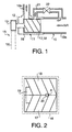
- an engine of an automobile or the like has an intake air pipe 10 and a screw supercharger 11 connected to the intake air pipe 10.
- the screw supercharger 11 compresses an intake air to supply a compressed air to the engine 10.
- a shaft 12 of the screw supercharger 11 is connected to a crankshaft of the engine (not shown) by a connection mechanism 15 including a pulley 13 and a belt 14.
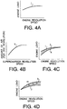
- the screw supercharger 11 has a casing 16 and a couple of male and female screw rotors 17 and 18 engaged with each other.
- the screw rotors 17 and 18 cooperatively rotate in the casing 16 to compress an intake air entering from an upstream pipe segment 10a of the intake air pipe 10, and eventually discharge a compressed air to a downstream pipe segment 10b.
- the downstream pipe segment 10b extends from an outlet 19 of the supercharger 11 toward the engine.
- the screw supercharger 11 also has an intermediate opening 20 at a position slightly spaced leftward from a compression start point "p" of the supercharger 11.
- the supercharger 11 performs suction and compression inside the casing 16. Suction is necessary to introduce the intake air into the casing 16 from the upstream intake air pipe 10a and compression is necessary to supply a compressed air to the engine via the downstream air pipe 10b. Inside the supercharger 11, therefore, the air pressure increases from its inlet to outlet and there is a compression start point "p". The right side of the point "p" is a suction area.
- a bypass pipe 21 extends from the recirculation opening 20 to the upstream intake air pipe 10a, and a duty solenoid valve 22 is provided on the bypass pipe 21 for arbitrarily adjusting an air flow rate of the compressed air to be returned to the inlet of the supercharger 11.
- a controller to control the engine, and the duty ratio of the solenoid valve 22 is determined by this controller according to a load of the engine.
- the amount of air to be recirculated to the upstream pipe segment 10a is adjusted by the controller based on the running condition of the vehicle.
- Fine control of the duty solenoid valve 22 is feasible using an electric signal and/or frequency adjustment.
- the screw supercharger 11 is originally designed to suit for a low speed condition of the engine.
- the amount of the supercharged air to be supplied from the supercharger 11 matches the low speed condition of the engine.
- an excessive amount of air tends to be supplied to the engine when the engine revolution speed becomes higher.
- the supercharger arrangement of this invention has the bypass pipe 21 so that the amount of air to be supplied to the engine from the supercharger 11 is controllable (reducible) by recirculating part of the intake air to the upstream intake air pipe 10a.
- the duty solenoid valve 22 is adjusted such that an appropriate amount of air is also supplied to the engine when the engine revolution speed is high.
- the screw supercharger 11 is driven by the power transmission mechanism 15 so that an intake air flowing from the upstream air pipe 10a is compressed between the male and female rotors 17 and 18 of the supercharger 11 and the compressed air is fed to the engine from the supercharger 10 through the downstream air pipe 10b.
- Figure 3A shows relationship between an engine load and an engine rotational speed when the vehicle is operated in the normal manner as mentioned above.
- the black dot "a” indicates the idling condition
- the white dot “b” indicates the constant speed driving condition
- the curve “c” indicates the engine load.
- the engine load increases as the vehicle is accelerated from the idling condition "a” until it reaches a peak point. The engine load then decreases gradually until the constant speed driving point "b" while the engine revolution speed is also increasing.
- a range from the idling point "a" to the maximum engine load point is referred to a full load condition area, and a range from the maximum engine load point to the constant speed point "b" is referred to as a partial load condition area and indicated by "d".
- FIG 3B illustrates the supercharger load relative to the supercharger revolution speed when the engine is operated in the above mentioned ordinary manner.
- the supercharger load is basically determined by the air flow rate at the exit of the supercharger 11.
- the curve “e” indicates a case where the amount of air (air flow rate) to be supplied to the engine is controlled to an optimum value. If the amount of air to be supplied to the engine is not controlled, the supercharger load takes a certain value in a shaded area "f" above the curve "e". This means that the supercharger 11 requires an additional work or energy if the air to be supplied to the engine from the supercharger 11 is not adjusted.
- the point “a” represents the idling and the point “b” represents the constant speed driving, which is the same as Figure 3A.
- FIG. 3C illustrates a duty ratio of the duty solenoid valve 22 relative to the revolution speed of the supercharger 11.
- the duty solenoid valve 22 is controlled according to this diagram in this particular embodiment.
- the duty ratio drops to 0% from 100%.
- the duty ratio gradually increases as indicated by the curve "g" until the acceleration is finished and the vehicle is brought into the constant speed condition "b".
- the duty ratio is raised to 100% as indicated by the curve "h”.
- the solenoid valve 22 is closed when its duty ratio is 0% and is always opened when 100%.
- Signals used to control the duty ratio of the duty solenoid valve 22 may be:
- the engine does not demonstrate its maximum theoretical output in an actual driving.
- An actual upper limit of the engine output is lower than a theoretical value due to knocking in case of gasoline engine equipped with a supercharger.
- the maximum output of the engine without causing knocking varies with a running condition of the engine, but it is generally determined by the intake air temperature (or the supercharger exit temperature) and the intake air pressure.
- the engine can demonstrate its possible maximum output when it is operated at a high speed but cannot when it is operated at a slower speed.
- the maximum engine output ("k) under the low speed condition is considerably below the knocking limitation "j".
- the shaded area "l" is an area in which the engine output is possibly raised.
- certain measures in addition to the supercharger 11 should be taken to raise the engine output toward the curve "j". Therefore, this supercharger setting is not preferable.
- Figure 4D illustrates a case where the supercharger has a characteristic curve "k" not to cause knocking under the low speed condition, i.e., the supercharger is designed to match the low speed condition (the curve "k” meets the curve "j" at the left end). Therefore, the engine demonstrates the possible maximum output when it is operated at the low speed. When the engine is operated at a high speed, however, an excessive amount of air tends to be supplied to the engine. To avoid such a undesired situation, some of the air compressed in the supercharger 11 is returned to the supercharge inlet by the bypass line 21 in the present invention.
- the supercharger characteristic curve "k" is shifted downward as indicated by the arrows in Figure 4D.
- the shaded area (over air feeding area) "m” can be eliminated in the invention. Accordingly, the supercharger can assist the engine such that the engine can demonstrate the possible maximum output under both the low and high speed conditions.
- the intake air is returned to the upstream intake air pipe 10a when it is slightly compressed by the supercharger 11. Therefore, the recirculated intake air does not have a high temperature. As a result, it is possible to prevent elevation of the intake air temperature. Thus, an intercooler is not needed, unlike a conventional arrangement.
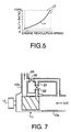
- FIG. 5 illustrates the relationship between the duty ratio of the solenoid valve 22 and the engine revolution speed.
- the duty solenoid valve 22 is controlled according to the curve "n" in the present invention. If a simple ON-OFF valve is employed instead of the duty solenoid valve, the engine output changes stepwise as indicated by the dotted line "o". This is undesirable. Also, knocking likely occurs so that the engine operation may be disabled.
- the duty solenoid valve 22 is employed and its duty ratio is adjusted according to the control curve "n" so as to appropriately control the flow rate of the air to be supplied to the engine from the supercharger. By such control, occurrence of knocking is prevented and the engine output changes smoothly in accordance with a running condition of the vehicle.
- the signals from the engine revolution sensor, air flow meter, accelerator sensor, etc are used in controlling the duty solenoid valve 22.
- the knocking limitation changes with various reasons such as an atmospheric temperature and a kind of fuel (octane number).
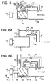
- FIG. 6 illustrated is a second embodiment of the present invention. Like numerals are assigned to like parts in Figures 1 and 6, and description of such parts may be omitted below.
- a second bypass passage 24 is provided extending from the downstream intake air pipe 10b to the upstream intake air pipe 10a in addition to the first bypass passage 21 connecting the screw supercharger 11 to the upstream intake air pipe 10a.
- a second valve 26 is provided in the second bypass passage 24 for regulating a flow rate of air allowed to be recirculated to the upstream intake air pipe 10a from the downstream intake air pipe 10b.
- part of the first bypass line 21 serves part of the second bypass line 24 (i.e., the second bypass line 24 merges into the first bypass line 21).
- the second valve 26 is located in the second bypass line 24 before the second bypass line 24 joins to the first bypass line 21.
- Opening/closing operations of the first and second bypass valves 22 and 26 may be performed in the following manner.
- the intake air is returned to the upper intake air pipe 10a from the screw supercharger 11 only. This is the same as the first embodiment.
- the two bypass lines 21 and 24 are opened. Consequently, the intake air is returned to the upstream intake air pipe 10a not only from the supercharger 11 but also from the downstream air intake pipe 10b.
- the amount of the recirculated air is the maximum in this case. In other words, the work needed to drive the supercharger is the minimum.
- the second bypass passage 24 is then opened to further reduce the wasted work of the screw supercharger 11.
- the second bypass passage 24 is only opened. Since the first valve 22 is located in the first bypass passage 21 after the second bypass passage 24 merges into the first bypass passage 21, the intake air from the downstream intake air pipe 10b is not introduced to the upstream intake air pipe 10a. The intake air is supplied to the screw supercharger 11 from the downstream air pipe 10b.
- This bypassing way is used when positively elevating the engine intake air temperature. For instance, (3) is employed to make a catalyst reactive soon after the engine is first turned on (i.e., when the engine is cold).
- both of the bypass passages are closed. This valve setting is utilized when the engine is operated in a full load condition (i.e., when the engine requires the maximum supercharging).
- second bypass passage 24' may be completely separated from the first bypass passage 21 as depicted in Figure 6B.
- Figure 7 illustrates a third embodiment of the present invention.
- the supercharger arrangement of this embodiment is similar to that shown in Figure 6, but location of the first valve 22 of the first bypass passage 21 is different. Specifically, the first valve 22 is provided in the first bypass passage 21 before the second bypass passage 24 merges into the first bypass passage 21. Therefore, when the first bypass valve 22 is closed, the intake air is not introduced to the supercharger 11. Opening/closing operations of the first and second bypass valves 22 and 26 may be performed in the following manner.
- the two bypass lines 21 and 24 are both opened. Consequently, the intake air is returned to the upstream intake air pipe 10a not only from the supercharger 11 but also from the downstream air intake pipe 10b.
- the amount of the recirculated air is the maximum in this case. In other words, the work needed to drive the supercharger is the minimum.
- the second bypass passage 24 is then opened to further reduce the wasted work of the screw supercharger 11.
- the second bypass passage 24 is only opened. Since the first bypass valve 22 closes the way to the supercharger 11, the intake air from the downstream intake air pipe 10b is not introduced to the supercharger 11 but to the upstream intake air pipe 10a. This bypassing way is also used when positively elevating the engine intake air temperature. For instance, (3') is employed to make a catalyst reactive soon after the engine is first turned on.
- any suitable valve such as a valve having a stepping motor may be employed instead of the duty solenoid valve 22/26 as long as the valve can change the flow rate of the air passing therethrough.
Landscapes
- Engineering & Computer Science (AREA)
- Chemical & Material Sciences (AREA)
- Combustion & Propulsion (AREA)
- Mechanical Engineering (AREA)
- General Engineering & Computer Science (AREA)
- Supercharger (AREA)
- Magnetically Actuated Valves (AREA)
Applications Claiming Priority (3)
| Application Number | Priority Date | Filing Date | Title |
|---|---|---|---|
| JP127371/97 | 1997-05-16 | ||
| JP9127371A JPH10317980A (ja) | 1997-05-16 | 1997-05-16 | 自動車用スクリュ形過給機 |
| JP12737197 | 1997-05-16 |
Publications (3)
| Publication Number | Publication Date |
|---|---|
| EP0878614A2 true EP0878614A2 (fr) | 1998-11-18 |
| EP0878614A3 EP0878614A3 (fr) | 1999-08-18 |
| EP0878614B1 EP0878614B1 (fr) | 2002-09-25 |
Family
ID=14958329
Family Applications (1)
| Application Number | Title | Priority Date | Filing Date |
|---|---|---|---|
| EP98108900A Expired - Lifetime EP0878614B1 (fr) | 1997-05-16 | 1998-05-15 | Suralimenteur à vis pour véhicule |
Country Status (4)
| Country | Link |
|---|---|
| US (1) | US6055967A (fr) |
| EP (1) | EP0878614B1 (fr) |
| JP (1) | JPH10317980A (fr) |
| DE (1) | DE69808172T2 (fr) |
Families Citing this family (14)
| Publication number | Priority date | Publication date | Assignee | Title |
|---|---|---|---|---|
| AU2002227507A1 (en) * | 2000-07-28 | 2002-02-13 | Visteon Global Technologies, Inc. | An air intake arrangement for an internal combustion engine |
| US6892713B2 (en) * | 2000-07-28 | 2005-05-17 | Visteon Global Technologies, Inc. | Air intake arrangement for an internal combustion engine |
| US6408832B1 (en) * | 2001-03-26 | 2002-06-25 | Brunswick Corporation | Outboard motor with a charge air cooler |
| US6405692B1 (en) * | 2001-03-26 | 2002-06-18 | Brunswick Corporation | Outboard motor with a screw compressor supercharger |
| US6378506B1 (en) * | 2001-04-04 | 2002-04-30 | Brunswick Corporation | Control system for an engine supercharging system |
| JP2004148917A (ja) * | 2002-10-29 | 2004-05-27 | Kawasaki Heavy Ind Ltd | 小型滑走艇 |
| US7080511B1 (en) * | 2005-01-12 | 2006-07-25 | Detroit Diesel Corporation | Method for controlling engine air/fuel ratio |
| US8371120B2 (en) * | 2008-01-15 | 2013-02-12 | Southwest Research Institute | HCCI combustion timing control with decoupled control of in-cylinder air/EGR mass and oxygen concentration |
| US8813492B2 (en) * | 2009-10-14 | 2014-08-26 | Hansen Engine Corporation | Internal combustion engine and supercharger |
| US8925528B2 (en) * | 2012-06-26 | 2015-01-06 | Ford Global Technologies, Llc | Engine balancing supercharger |
| CN104895790B (zh) * | 2015-05-19 | 2017-12-08 | 西安交通大学 | 一种具有中间抽气功能的双螺杆压缩机及多温区热泵系统 |
| CN105386980B (zh) * | 2015-11-30 | 2018-04-06 | 珠海格力电器股份有限公司 | 一种螺杆压缩机及空调系统 |
| US20170276076A1 (en) * | 2016-03-28 | 2017-09-28 | Hamburger's Specialty Vehicles, Inc. | Supercharger bypass valve and method of controlling same |
| CN107514363A (zh) * | 2017-08-28 | 2017-12-26 | 珠海格力电器股份有限公司 | 螺杆压缩机及其容量调节装置和容量调节方法,空调系统 |
Family Cites Families (11)
| Publication number | Priority date | Publication date | Assignee | Title |
|---|---|---|---|---|
| SE432465B (sv) * | 1980-06-02 | 1984-04-02 | Sullair Tech Ab | Ventilarrangemang for kapacitetsreglering av skruvkompressorer |
| JPS6183483A (ja) * | 1984-10-01 | 1986-04-28 | Toyota Motor Corp | ノツキング抑制式過給機付き内燃機関の制御装置 |
| JPS62199926A (ja) * | 1986-02-28 | 1987-09-03 | Toyota Motor Corp | 過給機付き内燃機関のノツキング制御装置 |
| JPH0318625A (ja) * | 1989-06-14 | 1991-01-28 | Mazda Motor Corp | 機械式過給機付エンジンの制御装置 |
| JPH0337326A (ja) * | 1989-07-03 | 1991-02-18 | Ishikawajima Harima Heavy Ind Co Ltd | 機械駆動式過給機 |
| JPH03117693A (ja) * | 1989-09-29 | 1991-05-20 | Mazda Motor Corp | ねじ式機械過給機 |
| JPH03294625A (ja) * | 1990-04-09 | 1991-12-25 | Ishikawajima Harima Heavy Ind Co Ltd | 複合過給機の過給制御方法 |
| US5127386A (en) * | 1990-06-01 | 1992-07-07 | Ingersoll-Rand Company | Apparatus for controlling a supercharger |
| JPH07233730A (ja) * | 1994-02-22 | 1995-09-05 | Tochigi Fuji Ind Co Ltd | 機械式過給機 |
| JPH0814054A (ja) * | 1994-06-24 | 1996-01-16 | Tochigi Fuji Ind Co Ltd | スクリュー式過給機 |
| JP3037326B1 (ja) | 1999-03-09 | 2000-04-24 | 静岡日本電気株式会社 | 携帯無線機 |
-
1997
- 1997-05-16 JP JP9127371A patent/JPH10317980A/ja active Pending
-
1998
- 1998-05-05 US US09/073,397 patent/US6055967A/en not_active Expired - Lifetime
- 1998-05-15 EP EP98108900A patent/EP0878614B1/fr not_active Expired - Lifetime
- 1998-05-15 DE DE69808172T patent/DE69808172T2/de not_active Expired - Lifetime
Non-Patent Citations (1)
| Title |
|---|
| None |
Also Published As
| Publication number | Publication date |
|---|---|
| JPH10317980A (ja) | 1998-12-02 |
| US6055967A (en) | 2000-05-02 |
| EP0878614B1 (fr) | 2002-09-25 |
| DE69808172T2 (de) | 2003-05-22 |
| DE69808172D1 (de) | 2002-10-31 |
| EP0878614A3 (fr) | 1999-08-18 |
Similar Documents
| Publication | Publication Date | Title |
|---|---|---|
| EP0878614B1 (fr) | Suralimenteur à vis pour véhicule | |
| US5117799A (en) | Control system for a supercharged internal combustion engine | |
| US6343473B1 (en) | Hybrid supercharged engine | |
| US4249382A (en) | Exhaust gas recirculation system for turbo charged engines | |
| US4505117A (en) | Turbocharged internal combustion engine having an engine driven positive displacement compressor | |
| US4730457A (en) | Supercharging system for automotive engines | |
| US4702218A (en) | Engine intake system having a pressure wave supercharger | |
| US5133188A (en) | Supercharged engine | |
| US6050094A (en) | Supercharged internal combustion engine | |
| US5427079A (en) | Supercharged engine with variable ratio drive supercharger | |
| US5307783A (en) | Boost pressure control system for an engine | |
| JPS61232336A (ja) | 内燃機関の運転方法とこの方法を実施するための内燃機関 | |
| US20100287932A1 (en) | Internal-combustion-engine control apparatus | |
| US4589396A (en) | Supercharger control in automobile engine system | |
| US7810329B2 (en) | Dual-charged internal combustion engine and method for operating the same | |
| EP0297287A1 (fr) | Moteur du type "turbo-compound" | |
| EP0547111A1 (fr) | Moteur surcomprime a combustion interne | |
| EP0392330B1 (fr) | Système de commande de moteur à compresseur mécanique | |
| JPH09112287A (ja) | 機械式過給機付エンジンの排気循環装置 | |
| JPH0734889A (ja) | 過給機付エンジンの制御方法 | |
| JPS62276223A (ja) | タ−ボチヤ−ジヤの過給圧制御装置 | |
| JPH03202635A (ja) | 車両用排気ターボチャージャ付エンジンの過給圧制御装置 | |
| JPH05125947A (ja) | 内燃機関の吸気制御装置 | |
| JPS6338614A (ja) | 過給機付き内燃機関の過給圧制御装置 | |
| EP0875675A2 (fr) | Système de suralimentation de moteur avec suralimenteur du type à vis |
Legal Events
| Date | Code | Title | Description |
|---|---|---|---|
| PUAI | Public reference made under article 153(3) epc to a published international application that has entered the european phase |
Free format text: ORIGINAL CODE: 0009012 |
|
| AK | Designated contracting states |
Kind code of ref document: A2 Designated state(s): DE FR GB |
|
| AX | Request for extension of the european patent |
Free format text: AL;LT;LV;MK;RO;SI |
|
| PUAL | Search report despatched |
Free format text: ORIGINAL CODE: 0009013 |
|
| AK | Designated contracting states |
Kind code of ref document: A3 Designated state(s): AT BE CH CY DE DK ES FI FR GB GR IE IT LI LU MC NL PT SE |
|
| AX | Request for extension of the european patent |
Free format text: AL;LT;LV;MK;RO;SI |
|
| RIC1 | Information provided on ipc code assigned before grant |
Free format text: 6F 02B 33/44 A, 6F 02B 33/36 B |
|
| 17P | Request for examination filed |
Effective date: 19991006 |
|
| AKX | Designation fees paid |
Free format text: DE FR GB |
|
| 17Q | First examination report despatched |
Effective date: 20010502 |
|
| GRAG | Despatch of communication of intention to grant |
Free format text: ORIGINAL CODE: EPIDOS AGRA |
|
| GRAG | Despatch of communication of intention to grant |
Free format text: ORIGINAL CODE: EPIDOS AGRA |
|
| GRAH | Despatch of communication of intention to grant a patent |
Free format text: ORIGINAL CODE: EPIDOS IGRA |
|
| GRAH | Despatch of communication of intention to grant a patent |
Free format text: ORIGINAL CODE: EPIDOS IGRA |
|
| GRAA | (expected) grant |
Free format text: ORIGINAL CODE: 0009210 |
|
| AK | Designated contracting states |
Kind code of ref document: B1 Designated state(s): DE FR GB |
|
| REG | Reference to a national code |
Ref country code: GB Ref legal event code: FG4D |
|
| REF | Corresponds to: |
Ref document number: 69808172 Country of ref document: DE Date of ref document: 20021031 |
|
| ET | Fr: translation filed | ||
| PLBE | No opposition filed within time limit |
Free format text: ORIGINAL CODE: 0009261 |
|
| STAA | Information on the status of an ep patent application or granted ep patent |
Free format text: STATUS: NO OPPOSITION FILED WITHIN TIME LIMIT |
|
| 26N | No opposition filed |
Effective date: 20030626 |
|
| PGFP | Annual fee paid to national office [announced via postgrant information from national office to epo] |
Ref country code: GB Payment date: 20140514 Year of fee payment: 17 |
|
| PGFP | Annual fee paid to national office [announced via postgrant information from national office to epo] |
Ref country code: FR Payment date: 20140509 Year of fee payment: 17 Ref country code: DE Payment date: 20140507 Year of fee payment: 17 |
|
| REG | Reference to a national code |
Ref country code: DE Ref legal event code: R082 Ref document number: 69808172 Country of ref document: DE Representative=s name: SCHAUMBURG & PARTNER PATENTANWAELTE MBB, DE Ref country code: DE Ref legal event code: R082 Ref document number: 69808172 Country of ref document: DE Representative=s name: SCHAUMBURG & PARTNER PATENTANWAELTE GBR, DE |
|
| REG | Reference to a national code |
Ref country code: DE Ref legal event code: R119 Ref document number: 69808172 Country of ref document: DE |
|
| GBPC | Gb: european patent ceased through non-payment of renewal fee |
Effective date: 20150515 |
|
| REG | Reference to a national code |
Ref country code: FR Ref legal event code: ST Effective date: 20160129 |
|
| PG25 | Lapsed in a contracting state [announced via postgrant information from national office to epo] |
Ref country code: DE Free format text: LAPSE BECAUSE OF NON-PAYMENT OF DUE FEES Effective date: 20151201 Ref country code: GB Free format text: LAPSE BECAUSE OF NON-PAYMENT OF DUE FEES Effective date: 20150515 |
|
| PG25 | Lapsed in a contracting state [announced via postgrant information from national office to epo] |
Ref country code: FR Free format text: LAPSE BECAUSE OF NON-PAYMENT OF DUE FEES Effective date: 20150601 |