EP0879755A2 - Dispositif pour supporter des batteries pour motocyclette - Google Patents
Dispositif pour supporter des batteries pour motocyclette Download PDFInfo
- Publication number
- EP0879755A2 EP0879755A2 EP98109166A EP98109166A EP0879755A2 EP 0879755 A2 EP0879755 A2 EP 0879755A2 EP 98109166 A EP98109166 A EP 98109166A EP 98109166 A EP98109166 A EP 98109166A EP 0879755 A2 EP0879755 A2 EP 0879755A2
- Authority
- EP
- European Patent Office
- Prior art keywords
- battery
- battery holder
- supporting apparatus
- motorcycles
- engine
- Prior art date
- Legal status (The legal status is an assumption and is not a legal conclusion. Google has not performed a legal analysis and makes no representation as to the accuracy of the status listed.)
- Granted
Links
- 239000007858 starting material Substances 0.000 claims description 10
- 239000002828 fuel tank Substances 0.000 abstract description 12
- 238000012423 maintenance Methods 0.000 abstract description 9
- 239000000463 material Substances 0.000 description 4
- 239000002184 metal Substances 0.000 description 4
- 238000007689 inspection Methods 0.000 description 3
- 238000010168 coupling process Methods 0.000 description 2
- 238000005859 coupling reaction Methods 0.000 description 2
- 229910000831 Steel Inorganic materials 0.000 description 1
- 238000010276 construction Methods 0.000 description 1
- 230000008878 coupling Effects 0.000 description 1
- 238000005242 forging Methods 0.000 description 1
- 239000011347 resin Substances 0.000 description 1
- 229920005989 resin Polymers 0.000 description 1
- 239000010959 steel Substances 0.000 description 1
Images


Classifications
-
- B—PERFORMING OPERATIONS; TRANSPORTING
- B62—LAND VEHICLES FOR TRAVELLING OTHERWISE THAN ON RAILS
- B62K—CYCLES; CYCLE FRAMES; CYCLE STEERING DEVICES; RIDER-OPERATED TERMINAL CONTROLS SPECIALLY ADAPTED FOR CYCLES; CYCLE AXLE SUSPENSIONS; CYCLE SIDE-CARS, FORECARS, OR THE LIKE
- B62K11/00—Motorcycles, engine-assisted cycles or motor scooters with one or two wheels
-
- B—PERFORMING OPERATIONS; TRANSPORTING
- B62—LAND VEHICLES FOR TRAVELLING OTHERWISE THAN ON RAILS
- B62J—CYCLE SADDLES OR SEATS; AUXILIARY DEVICES OR ACCESSORIES SPECIALLY ADAPTED TO CYCLES AND NOT OTHERWISE PROVIDED FOR, e.g. ARTICLE CARRIERS OR CYCLE PROTECTORS
- B62J43/00—Arrangements of batteries
- B62J43/20—Arrangements of batteries characterised by the mounting
-
- B—PERFORMING OPERATIONS; TRANSPORTING
- B62—LAND VEHICLES FOR TRAVELLING OTHERWISE THAN ON RAILS
- B62J—CYCLE SADDLES OR SEATS; AUXILIARY DEVICES OR ACCESSORIES SPECIALLY ADAPTED TO CYCLES AND NOT OTHERWISE PROVIDED FOR, e.g. ARTICLE CARRIERS OR CYCLE PROTECTORS
- B62J43/00—Arrangements of batteries
- B62J43/30—Arrangements of batteries for providing power to equipment other than for propulsion
-
- B—PERFORMING OPERATIONS; TRANSPORTING
- B62—LAND VEHICLES FOR TRAVELLING OTHERWISE THAN ON RAILS
- B62K—CYCLES; CYCLE FRAMES; CYCLE STEERING DEVICES; RIDER-OPERATED TERMINAL CONTROLS SPECIALLY ADAPTED FOR CYCLES; CYCLE AXLE SUSPENSIONS; CYCLE SIDE-CARS, FORECARS, OR THE LIKE
- B62K19/00—Cycle frames
- B62K19/30—Frame parts shaped to receive other cycle parts or accessories
- B62K19/40—Frame parts shaped to receive other cycle parts or accessories for attaching accessories, e.g. article carriers, lamps
Definitions
- the present invention relates to a battery supporting apparatus for motorcycles.
- a battery for motorcycles are mostly arranged immediately under the seat, but sometimes it is arranged below a swing arm, as shown in Japanese Patent Application Laid-Open Hei 1 No. 212683.
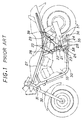
- the left and right lower metal fittings 21 are fabricated by forging which are separated into front and back parts, designating a spindle hole as a split face, and subsequently welded together to form a roughly Y-shape.
- An engine-coupling boss 23, a step-mounting boss 24, and a battery holder-mounting boss 25 are integrally formed to the lower metal fittings 21, and machined into screws, respectively.
- a kickstand bracket 26 is welded thereto.
- lower ends of front pipes 28 welded to a main pipe 7 are inserted into and welded to the upper ends thereof, and front ends of the back pipes 29 are inserted into and welded to the upper ends thereof.
- a back ends of down pipes 30 are inserted into and welded to the lower ends thereof.
- the front ends of the main pipe 27 and the down pipes 30 are coupled to ahead pipe 31.
- To the head pipe 31 is attached a telescopic front fork 32.
- To the boss 23 is axially mounted an engine case 33.
- To the boss 24 is axially mounted a step.
- To the boss 25 is attached a battery holder 36 mounted with a main stand 35, and a battery 37 is placed in the battery holder 36.
- a side stand 38 To the bracket 26 is axially mounted a side stand 38.
- aback fork 39 (swing arm) is axially mounted with a spindle.
- One example of the conventional motorcycle is as described above.
- the present invention has been devised in view of the above problems. It is the object of the present invention, therefore, to provide a battery supporting apparatus for motorcycles, in which the capacity of the fuel tank and the like can be sufficiently secured, as well as the workability of the battery maintenance can be improved, by arranging a battery holder between down pipes.
- the present invention is constituted so as to attain the above object, and the gist is as follows.
- a battery supporting apparatus for motorcycles comprises: a battery holder is arranged between lower parts of a pair of right and left down pipes which hang from the front and upper side of the engine toward the front of the engine case and downward.
- a battery supporting apparatus for motorcycles comprises: the battery holder is arranged in front of a starter motor located on the front part of the engine case.
- a battery supporting apparatus for motorcycles having the aforementioned anyone of first through fourth features comprises: a detachable lid is arranged on the front face of the battery holder.
- the capacity of the fuel tank and the like can be sufficiently secured and the workability of the battery maintenance can be improved.
- the starter motor is protected from pebbles or the like kicked up by the front wheel.
- the maintenance of the oil filter element is made possible without detaching the battery holder.
- FIG. 1 is a general side view of one example of the conventional motorcycle.
- FIG. 2 is a general side view of the motorcycle according to the embodiment of the present invention.
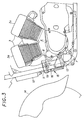
- FIG. 3 is a side view showing the lower part of the down pipe of a motorcycle.
- FIG. 4 is a perspective view showing the main part of the present embodiment.
- FIG. 2 ⁇ FIG. 4 are views for explaining the battery supporting apparatus for motorcycles according to this embodiment.
- FIG. 2 is a general side view of the motorcycle, and numeral 1 denotes a saddle-type seat, and a fuel tank 2 is installed immediately under the seat 1, located in front of a rear wheel rw, and a V-type two-cylinder engine 3 is installed in front of the fuel tank 2.
- a teardrop-type (seen from the side) cover 6a on which meters are installed which is also a cover for an air cleaner case 6 described later.
- a cover 2a is arranged on the outer side of the fuel tank 2 so that it overlies the fuel tank 2, when being seen from the side, thus the fuel tank 2 cannot be seen from outside.
- Each cylinder 3a, 3a of the engine 3 is mounted on the upper portion of the engine case 4, and exhaust pipes 5, 5 are connected from the front and the back of cylinders 3a, 3a which are around the engine 3 (from outside of the engine).
- a carburetor (not shown) is arranged inside opposite to the side where the exhaust pipes 5, 5 of respective cylinders 3a, 3a of the engine are mounted.
- the air cleaner case 6 is installed on the upper portion of the engine 3, a cartridge-type oil filter element 7 having a roughly cylindrical appearance projects forward from the lower part of the front portion of the engine case 4, as well as a starter motor 8 is arranged in the front portion of the engine case 4.
- a pair of right and left down pipes (frames) 11 hang from a head pipe 10 to which a telescopic front fork 9 for axially supporting the front wheel is attached, and the down pipes 11 extend backward, going round the lower part of the engine case 4.
- the down pipes 11 hang in front of the engine 3 and the engine case 4, and reach the lower part of the engine case 4.
- a radiator 12 is arranged on the upper part of the down pipes 11, as well as right and left engine-suspending plates 13L, 13R are fixed on the lower part of the down pipes 11.
- Numeral 14 denotes a front fender.
- a box-shaped battery holder 15 corresponding to the battery shape is arranged, located between lower parts of a pair of right and left down pipes 11 and backward of the front fender 14.
- the material of the battery holder 15 may be any material so far as it has a proper rigidity and durability, such as a material fabricated and formed from a metal plate, for example, a steel plate.
- the shape of the battery holder 15 has only to correspond to the battery shape, and it may have an optional shape such as a rectangular shape or a cylindrical shape, according to the battery shape.
- the front face of the battery holder 15 is sealed with a detachable lid 16, the battery holder 15 is placed and fixed on a channel-shaped supporting material 17 fixed on the lower part of the down pipes 11, and right and left sides thereof are fixed to the down pipes 11 with a coupling member 18 coupled to right and left sides of the battery holder 15.
- the upper portion of the battery holder 15 is covered with a battery cover 19 made of a resin or the like.
- the capacity of the fuel tank 2 and the like can be sufficiently secured and the workability of the battery maintenance can be improved.
- the starter motor 8 is protected from pebbles or the like kicked up by the front wheel.
- the maintenance of the oil filter element 7 can be done without detaching the battery holder 15.
- detachable lid 16 is arranged on the front face of the battery holder 15, and there is a space between the lid 16 and a front fender 14, at the time of detaching the lid 16, detaching work can be easily done by means of the forehand space, hence attaching and changing the battery and the inspection work can be easily and conveniently performed.
- the battery holder is arranged on the lower part of the down pipes, a wider space can be secured than the conventional embodiment, immediately under the seat, or downward of the swing arm.
- the freedom of layout is increased, and the capacity of the fuel tank and the muffler chamber can be expanded sufficiently, as well as the sitting height of the seat can be lowered.
- the starter motor since the battery holder is arranged in front of the starter motor, the starter motor is protected from pebbles or the like kicked up by the front wheel.
- the maintenance of the oil filter element can be done without detaching the battery holder.
Landscapes
- Engineering & Computer Science (AREA)
- Mechanical Engineering (AREA)
- Automatic Cycles, And Cycles In General (AREA)
Applications Claiming Priority (3)
| Application Number | Priority Date | Filing Date | Title |
|---|---|---|---|
| JP13225597A JP3482816B2 (ja) | 1997-05-22 | 1997-05-22 | 自動二輪車のバッテリ支持装置 |
| JP132255/97 | 1997-05-22 | ||
| JP13225597 | 1997-05-22 |
Publications (3)
| Publication Number | Publication Date |
|---|---|
| EP0879755A2 true EP0879755A2 (fr) | 1998-11-25 |
| EP0879755A3 EP0879755A3 (fr) | 2000-07-05 |
| EP0879755B1 EP0879755B1 (fr) | 2004-07-28 |
Family
ID=15077007
Family Applications (1)
| Application Number | Title | Priority Date | Filing Date |
|---|---|---|---|
| EP98109166A Expired - Lifetime EP0879755B1 (fr) | 1997-05-22 | 1998-05-20 | Dispositif pour supporter des batteries pour motocyclette |
Country Status (2)
| Country | Link |
|---|---|
| EP (1) | EP0879755B1 (fr) |
| JP (1) | JP3482816B2 (fr) |
Cited By (6)
| Publication number | Priority date | Publication date | Assignee | Title |
|---|---|---|---|---|
| EP1950128A1 (fr) * | 2007-01-23 | 2008-07-30 | Bayerische Motoren Werke Aktiengesellschaft | Motocyclette |
| EP2159145A1 (fr) * | 2008-08-29 | 2010-03-03 | Yamaha Motor Research & Development Europe s.r.l. | Ensemble pour motocyclette comportant un radiateur et une batterie, et motocyclette équipée d'un tel ensemble |
| WO2019047509A1 (fr) * | 2017-09-11 | 2019-03-14 | 广东工业大学 | Véhicule monorail à deux roues et procédé de commande d'équilibre correspondant |
| CN113460216A (zh) * | 2017-03-10 | 2021-10-01 | 印度摩托车国际有限公司 | 两轮式车辆 |
| USD1001687S1 (en) | 2018-09-10 | 2023-10-17 | Indian Motorcycle International, LLC | Motorcycle |
| US11873054B2 (en) | 2018-09-28 | 2024-01-16 | Indian Motorcycle International, LLC | Two-wheeled vehicle |
Families Citing this family (3)
| Publication number | Priority date | Publication date | Assignee | Title |
|---|---|---|---|---|
| US7007861B2 (en) | 2000-06-08 | 2006-03-07 | S.C. Johnson & Son, Inc. | Methods and personal protection devices for repelling insects |
| JP2006117174A (ja) * | 2004-10-25 | 2006-05-11 | Yamaha Motor Co Ltd | 自動二輪車 |
| JP2009161138A (ja) | 2008-01-10 | 2009-07-23 | Yamaha Motor Co Ltd | 自動二輪車の電源支持機構及びそれを備えた自動二輪車 |
Citations (1)
| Publication number | Priority date | Publication date | Assignee | Title |
|---|---|---|---|---|
| JPH01212683A (ja) | 1988-02-19 | 1989-08-25 | Suzuki Motor Co Ltd | オートバイのフレーム |
Family Cites Families (7)
| Publication number | Priority date | Publication date | Assignee | Title |
|---|---|---|---|---|
| DE2903742C2 (de) * | 1979-02-01 | 1981-06-19 | Bayerische Motoren Werke AG, 8000 München | Triebwerks-Anordnung für Motorräder |
| JPS58204918A (ja) * | 1982-05-24 | 1983-11-29 | Honda Motor Co Ltd | 自動二輪車のラジエ−タ装置 |
| JPS5950885A (ja) * | 1982-09-14 | 1984-03-24 | 本田技研工業株式会社 | 自動二輪車 |
| JPS6189145A (ja) * | 1984-10-05 | 1986-05-07 | Honda Motor Co Ltd | 自動二輪車 |
| JP3159437B2 (ja) * | 1989-07-25 | 2001-04-23 | スズキ株式会社 | 自動二輪車のバッテリー等の収容装置 |
| JPH06247365A (ja) * | 1993-02-23 | 1994-09-06 | Suzuki Motor Corp | オートバイのスターターモーター保護装置 |
| FR2761332B1 (fr) * | 1997-04-01 | 1999-06-04 | Eric Jean Offenstadt | Dispositif de reduction des transferts de charge des vehicules a 2 roues tels que motocyclettes et velomoteurs |
-
1997
- 1997-05-22 JP JP13225597A patent/JP3482816B2/ja not_active Expired - Fee Related
-
1998
- 1998-05-20 EP EP98109166A patent/EP0879755B1/fr not_active Expired - Lifetime
Patent Citations (1)
| Publication number | Priority date | Publication date | Assignee | Title |
|---|---|---|---|---|
| JPH01212683A (ja) | 1988-02-19 | 1989-08-25 | Suzuki Motor Co Ltd | オートバイのフレーム |
Cited By (12)
| Publication number | Priority date | Publication date | Assignee | Title |
|---|---|---|---|---|
| EP1950128A1 (fr) * | 2007-01-23 | 2008-07-30 | Bayerische Motoren Werke Aktiengesellschaft | Motocyclette |
| EP2159145A1 (fr) * | 2008-08-29 | 2010-03-03 | Yamaha Motor Research & Development Europe s.r.l. | Ensemble pour motocyclette comportant un radiateur et une batterie, et motocyclette équipée d'un tel ensemble |
| CN113460216A (zh) * | 2017-03-10 | 2021-10-01 | 印度摩托车国际有限公司 | 两轮式车辆 |
| US11702166B2 (en) | 2017-03-10 | 2023-07-18 | Indian Motorcycle International, LLC | Two-wheeled vehicle |
| CN113460216B (zh) * | 2017-03-10 | 2024-04-02 | 印度摩托车国际有限公司 | 两轮式车辆 |
| US12246790B2 (en) | 2017-03-10 | 2025-03-11 | Indian Motorcycle International, LLC | Two-wheeled vehicle |
| WO2019047509A1 (fr) * | 2017-09-11 | 2019-03-14 | 广东工业大学 | Véhicule monorail à deux roues et procédé de commande d'équilibre correspondant |
| USD1001687S1 (en) | 2018-09-10 | 2023-10-17 | Indian Motorcycle International, LLC | Motorcycle |
| USD1030561S1 (en) | 2018-09-10 | 2024-06-11 | Indian Motorcycle International, LLC | Motorcycle |
| USD1084956S1 (en) | 2018-09-10 | 2025-07-22 | Indian Motorcycle International, LLC | Motorcycle fuel tank cover |
| US11873054B2 (en) | 2018-09-28 | 2024-01-16 | Indian Motorcycle International, LLC | Two-wheeled vehicle |
| US12151767B2 (en) | 2018-09-28 | 2024-11-26 | Indian Motorcycle International, LLC | Two-wheeled vehicle |
Also Published As
| Publication number | Publication date |
|---|---|
| EP0879755A3 (fr) | 2000-07-05 |
| JPH10316068A (ja) | 1998-12-02 |
| JP3482816B2 (ja) | 2004-01-06 |
| EP0879755B1 (fr) | 2004-07-28 |
Similar Documents
| Publication | Publication Date | Title |
|---|---|---|
| JP7351250B2 (ja) | 鞍乗型車両 | |
| US9156513B2 (en) | Front cowl stay attachment structure for saddle-ride type vehicle | |
| JP3493344B2 (ja) | 騎乗型不整地走行車の排気装置 | |
| KR20040027336A (ko) | 저바닥식 차량의 엔진 탑재 구조 | |
| US6910716B2 (en) | Fuel tank mounting structure for motorcycles | |
| US11059539B2 (en) | Stay for saddle riding vehicle | |
| EP0879755A2 (fr) | Dispositif pour supporter des batteries pour motocyclette | |
| JP4008190B2 (ja) | 自動2輪車の車体構造 | |
| JP2001234747A (ja) | 自動二輪車用4サイクルエンジンのオイルフィルタおよびオイルクーラ取付け構造 | |
| JP5478182B2 (ja) | 鞍乗型車両のシートカウル構造 | |
| JP5292512B2 (ja) | 鞍乗り型車両の吸気系の配置構造 | |
| EP3524499B1 (fr) | Support d'un reservoir d'un véhicule de type à enfourcher | |
| EP3524498B1 (fr) | Tuyau de drainage de carburant couvert par le carénage d'un véhicule à enfourcher | |
| JPS5849581A (ja) | 自動二輪車の車体フレ−ム | |
| US9815521B2 (en) | Exhaust system of saddle-ride type vehicle | |
| JP3457303B2 (ja) | 自動二輪車におけるフロントトップカバーの取付け構造 | |
| JP3588514B2 (ja) | 自動二輪車のエアクリーナ装置 | |
| JP4267714B2 (ja) | 自動2輪車のメーター取付構造 | |
| JP4072999B2 (ja) | 自動二輪車の車体フレーム | |
| JP3877665B2 (ja) | 低床式車両の低床支持構造 | |
| JPH0274487A (ja) | 鞍乗型車両 | |
| JP3930101B2 (ja) | 自動2輪車の補機類配置構造 | |
| JP2011255828A (ja) | 自動二輪車の燃料タンク構造および自動二輪車の燃料タンクの取り付け方法 | |
| JP4291035B2 (ja) | 自動二輪車用二次空気供給装置の配置構造 | |
| JP7116025B2 (ja) | 鞍乗り型車両 |
Legal Events
| Date | Code | Title | Description |
|---|---|---|---|
| PUAI | Public reference made under article 153(3) epc to a published international application that has entered the european phase |
Free format text: ORIGINAL CODE: 0009012 |
|
| AK | Designated contracting states |
Kind code of ref document: A2 Designated state(s): FR GB |
|
| AX | Request for extension of the european patent |
Free format text: AL;LT;LV;MK;RO;SI |
|
| PUAL | Search report despatched |
Free format text: ORIGINAL CODE: 0009013 |
|
| AK | Designated contracting states |
Kind code of ref document: A3 Designated state(s): AT BE CH CY DE DK ES FI FR GB GR IE IT LI LU MC NL PT SE |
|
| AX | Request for extension of the european patent |
Free format text: AL;LT;LV;MK;RO;SI |
|
| 17P | Request for examination filed |
Effective date: 20000830 |
|
| 17Q | First examination report despatched |
Effective date: 20001114 |
|
| AKX | Designation fees paid |
Free format text: FR GB |
|
| REG | Reference to a national code |
Ref country code: DE Ref legal event code: 8566 |
|
| GRAP | Despatch of communication of intention to grant a patent |
Free format text: ORIGINAL CODE: EPIDOSNIGR1 |
|
| GRAS | Grant fee paid |
Free format text: ORIGINAL CODE: EPIDOSNIGR3 |
|
| GRAA | (expected) grant |
Free format text: ORIGINAL CODE: 0009210 |
|
| AK | Designated contracting states |
Kind code of ref document: B1 Designated state(s): FR GB |
|
| REG | Reference to a national code |
Ref country code: GB Ref legal event code: FG4D |
|
| ET | Fr: translation filed | ||
| PLBE | No opposition filed within time limit |
Free format text: ORIGINAL CODE: 0009261 |
|
| STAA | Information on the status of an ep patent application or granted ep patent |
Free format text: STATUS: NO OPPOSITION FILED WITHIN TIME LIMIT |
|
| 26N | No opposition filed |
Effective date: 20050429 |
|
| PGFP | Annual fee paid to national office [announced via postgrant information from national office to epo] |
Ref country code: GB Payment date: 20080521 Year of fee payment: 11 |
|
| GBPC | Gb: european patent ceased through non-payment of renewal fee |
Effective date: 20090520 |
|
| REG | Reference to a national code |
Ref country code: FR Ref legal event code: ST Effective date: 20100129 |
|
| PG25 | Lapsed in a contracting state [announced via postgrant information from national office to epo] |
Ref country code: FR Free format text: LAPSE BECAUSE OF NON-PAYMENT OF DUE FEES Effective date: 20090602 |
|
| PGFP | Annual fee paid to national office [announced via postgrant information from national office to epo] |
Ref country code: FR Payment date: 20080514 Year of fee payment: 11 |
|
| PG25 | Lapsed in a contracting state [announced via postgrant information from national office to epo] |
Ref country code: GB Free format text: LAPSE BECAUSE OF NON-PAYMENT OF DUE FEES Effective date: 20090520 |