EP0882547A2 - Mehrstufiger Montageroboter - Google Patents
Mehrstufiger Montageroboter Download PDFInfo
- Publication number
- EP0882547A2 EP0882547A2 EP98201817A EP98201817A EP0882547A2 EP 0882547 A2 EP0882547 A2 EP 0882547A2 EP 98201817 A EP98201817 A EP 98201817A EP 98201817 A EP98201817 A EP 98201817A EP 0882547 A2 EP0882547 A2 EP 0882547A2
- Authority
- EP
- European Patent Office
- Prior art keywords
- cylinder
- movable plate
- reciprocated
- plate
- pick
- Prior art date
- Legal status (The legal status is an assumption and is not a legal conclusion. Google has not performed a legal analysis and makes no representation as to the accuracy of the status listed.)
- Withdrawn
Links
Images

Classifications
-
- B—PERFORMING OPERATIONS; TRANSPORTING
- B25—HAND TOOLS; PORTABLE POWER-DRIVEN TOOLS; MANIPULATORS
- B25J—MANIPULATORS; CHAMBERS PROVIDED WITH MANIPULATION DEVICES
- B25J9/00—Program-controlled manipulators
- B25J9/0009—Constructional details, e.g. manipulator supports, bases
-
- B—PERFORMING OPERATIONS; TRANSPORTING
- B23—MACHINE TOOLS; METAL-WORKING NOT OTHERWISE PROVIDED FOR
- B23P—METAL-WORKING NOT OTHERWISE PROVIDED FOR; COMBINED OPERATIONS; UNIVERSAL MACHINE TOOLS
- B23P19/00—Machines for simply fitting together or separating metal parts or objects, or metal and non-metal parts, whether or not involving some deformation; Tools or devices therefor so far as not provided for in other classes
- B23P19/02—Machines for simply fitting together or separating metal parts or objects, or metal and non-metal parts, whether or not involving some deformation; Tools or devices therefor so far as not provided for in other classes for connecting objects by press fit or for detaching same
-
- B—PERFORMING OPERATIONS; TRANSPORTING
- B23—MACHINE TOOLS; METAL-WORKING NOT OTHERWISE PROVIDED FOR
- B23P—METAL-WORKING NOT OTHERWISE PROVIDED FOR; COMBINED OPERATIONS; UNIVERSAL MACHINE TOOLS
- B23P19/00—Machines for simply fitting together or separating metal parts or objects, or metal and non-metal parts, whether or not involving some deformation; Tools or devices therefor so far as not provided for in other classes
- B23P19/001—Article feeders for assembling machines
- B23P19/007—Picking-up and placing mechanisms
-
- B—PERFORMING OPERATIONS; TRANSPORTING
- B25—HAND TOOLS; PORTABLE POWER-DRIVEN TOOLS; MANIPULATORS
- B25J—MANIPULATORS; CHAMBERS PROVIDED WITH MANIPULATION DEVICES
- B25J15/00—Gripping heads and other end effectors
- B25J15/04—Gripping heads and other end effectors with provision for the remote detachment or exchange of the head or parts thereof
-
- B—PERFORMING OPERATIONS; TRANSPORTING
- B25—HAND TOOLS; PORTABLE POWER-DRIVEN TOOLS; MANIPULATORS
- B25J—MANIPULATORS; CHAMBERS PROVIDED WITH MANIPULATION DEVICES
- B25J15/00—Gripping heads and other end effectors
- B25J15/08—Gripping heads and other end effectors having finger members
- B25J15/10—Gripping heads and other end effectors having finger members with three or more finger members
-
- B—PERFORMING OPERATIONS; TRANSPORTING
- B65—CONVEYING; PACKING; STORING; HANDLING THIN OR FILAMENTARY MATERIAL
- B65G—TRANSPORT OR STORAGE DEVICES, e.g. CONVEYORS FOR LOADING OR TIPPING, SHOP CONVEYOR SYSTEMS OR PNEUMATIC TUBE CONVEYORS
- B65G47/00—Article or material-handling devices associated with conveyors; Methods employing such devices
- B65G47/74—Feeding, transfer, or discharging devices of particular kinds or types
- B65G47/90—Devices for picking-up and depositing articles or materials
-
- Y—GENERAL TAGGING OF NEW TECHNOLOGICAL DEVELOPMENTS; GENERAL TAGGING OF CROSS-SECTIONAL TECHNOLOGIES SPANNING OVER SEVERAL SECTIONS OF THE IPC; TECHNICAL SUBJECTS COVERED BY FORMER USPC CROSS-REFERENCE ART COLLECTIONS [XRACs] AND DIGESTS
- Y10—TECHNICAL SUBJECTS COVERED BY FORMER USPC
- Y10T—TECHNICAL SUBJECTS COVERED BY FORMER US CLASSIFICATION
- Y10T29/00—Metal working
- Y10T29/51—Plural diverse manufacturing apparatus including means for metal shaping or assembling
- Y10T29/5136—Separate tool stations for selective or successive operation on work
- Y10T29/5137—Separate tool stations for selective or successive operation on work including assembling or disassembling station
-
- Y—GENERAL TAGGING OF NEW TECHNOLOGICAL DEVELOPMENTS; GENERAL TAGGING OF CROSS-SECTIONAL TECHNOLOGIES SPANNING OVER SEVERAL SECTIONS OF THE IPC; TECHNICAL SUBJECTS COVERED BY FORMER USPC CROSS-REFERENCE ART COLLECTIONS [XRACs] AND DIGESTS
- Y10—TECHNICAL SUBJECTS COVERED BY FORMER USPC
- Y10T—TECHNICAL SUBJECTS COVERED BY FORMER US CLASSIFICATION
- Y10T29/00—Metal working
- Y10T29/53—Means to assemble or disassemble
- Y10T29/53313—Means to interrelatedly feed plural work parts from plural sources without manual intervention
Definitions
- the present invention relates to a multi-stage assembling robot having a progressive feeding device.
- An object of the present invention is to provide robot for a progressive multi-stage press machine using a die set and having a progressive pick-and-place device, whereby the robot may be simplified in construction, reduced in size, and manufactured at a low cost.
- a multi-stage assembling robot comprising, a die set having a base plate, vertical guide posts securely mounted on the base plate, a horizontal cylinder plate securely mounted on top portions of the guide posts, an upper movable plate and a lower movable plate which are slidably mounted on the guide posts, at least three sets of upper and lower dies mounted on the upper movable plate and base plate, a first cylinder mounted on the cylinder plate, the cylinder having a piston rod which is connected to the upper movable plate, a second cylinder mounted on an underside of the base plate, the second cylinder having a piston rod which is connected to the lower movable plate, a work pick-and-place device mounted on the lower movable plate provided to be reciprocated in the horizontal direction and reciprocated in the vertical direction so as to feed works to lower dies, at least three parts pick-and-place devices radially mounted on the base plate, each of the part pick-and-place devices being provided to be reciprocated in the horizontal direction and reciprocated
- the work pick-and-place device has at least three sets of grasping opposite fingers, each set of grasping fingers are reciprocated by opposite cylinders, and each of the part pick-and-place device has a chuck for grasping a part.
- two vertical guide posts 1 are securely mounted on a base plate 2.
- An upper movable plate 8 and a lower movable plate 10 are slidably mounted on the guide posts 1 by slidably engaging guide bushes 3 and 4, interposing ball sliders 5 between the guide bush and guide post 1.
- a horizontal cylinder plate 7 is secured to the guide post 1 at the top of each post and secured thereto by screw.
- a hydraulic cylinder 6 such as an oil hydraulic cylinder or pneumatic cylinder is vertically mounted on the cylinder plate 7 and secured thereto by screws.
- At least one pneumatic cylinder 11 is secured to the underside of the base plate 2, and a piston rod 12 thereof connected to the lower movable plate 10.
- the piston rod 9 is secured to the movable plate 8.
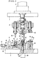
- the movable plate 8 has a punch 53, and dies 55 and 57 (Fig. 2). On the base plate 2, a lower die 54, 56 are mounted.
- a first pick-and-place device 13 for feeding works A to D and for taking out a processed work (Fig. 2).
- a pair of slide guide rails 16 are securely mounted on the lower movable plate 10 parallel with each other at the opposite sides of the lower die 54.
- a pair of slide blocks 15 are slidably mounted on each of the guide rails 16.
- a pair of L-shaped supporting plates 20 and 21 are secured to respective slide blocks 15. The ends of the supporting plates 20, 21 are connected by a connecting plate 22.
- a supporting plate 23 is secured to the ends of the slide guide rails 16.
- a pneumatic cylinder 24 is mounted on the supporting plate 23 and a piston rod 25 is connected to the connecting plate 22.
- Each grasping actuator comprises opposite pneumatic cylinders 18 and 19 secured to the opposite supporting plates 20, 21.
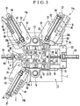
- the cylinders 18 and 19 are positioned on a first position P1, second position P2, and a third position P3 at predetermined equidistances, respectively.
- Opposite grasping fingers 28, 29 are secured to piston rods 26, 27 (Fig. 1b) of cylinders 18 and 19 by nuts 22 for grasping a work.
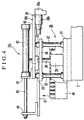
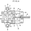
- Figs. 4 shows the part pick-and-place device 14a.
- the device has an elevating device 30,
- the device 30 has a pair of guide posts 32 secured on a base plate 31 which is securely mounted on the base plate 2.
- a movable plate 34 is vertically slidably mounted on the guide posts 32, interposing guide bushes 33 respectively.
- the movable plate 34 is connected to a piston rod 36 of a pneumatic cylinder 35 which is secured to the base plate 31.
- a slide guide rail 37 is secured to the movable plate 34.
- a slide block 38 is slidably mounted on the slide guide rail 37.
- a supporting plate 40 is secured to the slide block 38.
- a horizontal pneumatic cylinder 42 is secured to the supporting plate 40 through a connecting plate 41, and a piston rod 43 of the cylinder 42 is connected to the slide guide rail 37 through a connecting plate 44.
- a horizontal pneumatic cylinder 39 having a chuck 39a is secured by screws 39b.
- the chuck 39a is opened in a normal state.
- the chuck is closed for gripping a part B and opened again for releasing the work in accordance with the operation of the cylinder 39.
- the chuck device is well known.
- a guide rail 46 is connected to a well known parts feeder 45 and communicated with a groove 47 provided on the base plate 31.
- the part pick-and-place device 14b is provided for feeding a part C, and the device 14c is provided for feeding a part D.
- a guide rail 49 is securely mounted on a progressive feed line.
- a slide block 50 Slidably mounted on the guide rail 49 is a slide block 50 on which a part holder 48 is mounted.
- the slide block 50 is connected to a piston rod 52 of a pneumatic cylinder 51 mounted on the guide rail 49.
- the illustrated embodiment of the present invention is provided for assembling parts into a thermo-actuator provided in a wax-pellet thermostat for a cooling system of an automotive engine.
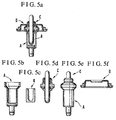
- Fig. 5a shows the thermo-actuator
- Figs. 5b to 5f shows respective parts for the thermo-actuator.
- a part A for a first step which has been worked and assembled at a previous stage is introduced in the part holder 48 through a chute (not shown) as shown in Figs. 2 and 3.
- the part A is transferred to the position P1 together with the part holder 48 by the piston 52 of the pneumatic cylinder 51.
- the chuck 39a which has been opened is lowered, holds a part B for the first step, and raised by the piston 36 of the pneumatic cylinder 35.
- the piston 43 of the pneumatic cylinder 42 causes the supporting plate 40 and chuck 39a to move forwardly to the position P1.
- chuck 39a is lowered by the piston 36 so that the part B is inserted into the part A.
- the chuck 39a is opened and raised and returned to the original position, keeping the chuck opened.
- the upper movable plate 8 is lowered by the operation of the cylinder 6, so that the punch 53 is inserted in the part B to form it into a proper shape to fit in the part A, thereby forming a fist step work assembly A1. Then, the movable plate 8 is raised.
- the piston rods 26 (Fig. 1b) of the cylinders 18 and 19 are forwardly moved, so that the fingers 28 and 29 at the position P1 grasp the work assembly A1.
- the base plate 10 of the work pick-and-place device 13 is raised by the operation of the pneumatic cylinder 11, and moved to the position P2 in Figs. 2 and 3, and lowered, so that the work assembly A1 is inserted in the die 54.
- the fingers 28 and 29 are opened, raised, returned to the position P1, and lowered.
- next parts A and B for a second step are engaged with each other in the above described operation to form a second step work assembly A1.
- a part C for the first step which has been assembled by another device (not shown) is inserted in the first step work assembly A1 by the part pick-and-place device 14b.
- the upper movable plate 8 is lowered and raised, so that the part B is fixed in the part A for the second step.
- the part C is engaged in the part B of the first step at the position P2 by the dies 54 and 55, thereby forming a first step work assembly A2.
- the work assembly A1 has a space a (Fig. 2) sufficient for receiving the fingers 28 and 29, the work assembly A2 engaged in the die 54 has not such a sufficient space.
- the work assembly A2 is raised by a collar 60 secured to a piston rod 59 of a pneumatic cylinder 58 so as to form a space a .
- fingers 28, 29 at the positions P1 and P2 carry the second step work assembly A1 and the first step work assembly A2 to the positions P2 and P3.
- the first step work assembly A2 is inserted in a die 56.
- a third step work assembly A1 and a second step work assembly A2 are assembled in the same operation as the above described operation.
- the part D is engaged by a die 57, so that a first step assembly A3 which is a finished work is assembled.
- fingers 28, 29 at the positions P1, P2 and P3 carry the assemblies A1, A2 and A3 to the position P2, P3 and P4.
- the finished work assembly A3 (Fig. 5a) is discharged by a chute (not shown).
- each of the cylinders 18 is set to a larger value than that of the cylinder 19 at the other side, so that each cylinder 18 has a larger air pressure than that of the cylinder 19. Therefore, the part engaged with the finger 28 of the cylinder 18 is not moved if the work is pushed by the finger 29 of the cylinder 19. Namely, the position of the work is determined by only the finger 28 of the cylinder 18. Thus, the centering of the work is accurately determined with respect to the center of each die. Consequently, the break of the die due to eccentric positioning of the work is prevented.
- the robot can be manufactured in small size and at a low cost.
Landscapes
- Engineering & Computer Science (AREA)
- Mechanical Engineering (AREA)
- Robotics (AREA)
- Manipulator (AREA)
- Automatic Assembly (AREA)
- Sheets, Magazines, And Separation Thereof (AREA)
- Mounting, Exchange, And Manufacturing Of Dies (AREA)
- Press Drives And Press Lines (AREA)
Applications Claiming Priority (3)
| Application Number | Priority Date | Filing Date | Title |
|---|---|---|---|
| JP184259/97 | 1997-06-06 | ||
| JP9184259A JPH11797A (ja) | 1997-06-06 | 1997-06-06 | ダイセット型多工程順送のロボット機械 |
| JP18425997 | 1997-06-06 |
Publications (2)
| Publication Number | Publication Date |
|---|---|
| EP0882547A2 true EP0882547A2 (de) | 1998-12-09 |
| EP0882547A3 EP0882547A3 (de) | 1999-07-28 |
Family
ID=16150194
Family Applications (1)
| Application Number | Title | Priority Date | Filing Date |
|---|---|---|---|
| EP98201817A Withdrawn EP0882547A3 (de) | 1997-06-06 | 1998-06-02 | Mehrstufiger Montageroboter |
Country Status (9)
| Country | Link |
|---|---|
| US (1) | US6138342A (de) |
| EP (1) | EP0882547A3 (de) |
| JP (1) | JPH11797A (de) |
| KR (1) | KR19990006681A (de) |
| CN (1) | CN1081496C (de) |
| AU (1) | AU702193B2 (de) |
| CA (1) | CA2239646A1 (de) |
| RU (1) | RU2142871C1 (de) |
| TW (1) | TW388731B (de) |
Cited By (3)
| Publication number | Priority date | Publication date | Assignee | Title |
|---|---|---|---|---|
| CN107962111A (zh) * | 2016-10-20 | 2018-04-27 | 盛安塑胶五金(上海)有限公司 | 一种模具冲头 |
| CN109016620A (zh) * | 2018-07-18 | 2018-12-18 | 芜湖康奇制药有限公司 | 一种药物生产用药料铺料压片装置 |
| CN112157408A (zh) * | 2020-08-13 | 2021-01-01 | 盐城工学院 | 工业机器人双机协作搬运系统与方法 |
Families Citing this family (16)
| Publication number | Priority date | Publication date | Assignee | Title |
|---|---|---|---|---|
| JP3392401B2 (ja) * | 2000-12-14 | 2003-03-31 | 東洋ゴム工業株式会社 | ゴムブッシュの外筒絞り加工を行う設備 |
| JP4382019B2 (ja) * | 2005-09-02 | 2009-12-09 | 本田技研工業株式会社 | コンロッドのブッシュの供給圧入装置 |
| US7673384B2 (en) * | 2006-04-27 | 2010-03-09 | Genesis Systems Group, Llc | Nut runner and hexabot robot |
| CN102950238B (zh) * | 2012-11-27 | 2014-12-10 | 中信重工机械股份有限公司 | 一种高精度自动对中式多工位工件夹送装置 |
| CN104175118A (zh) * | 2013-05-22 | 2014-12-03 | 北大方正集团有限公司 | 一种水平生产线及其中零部件的连接、安装及拆卸方法 |
| CN104209729A (zh) * | 2013-05-29 | 2014-12-17 | 江苏东方汽车装饰件总厂 | 一种安装汽车水箱安装孔上的保护扣用的工装 |
| CN103317717A (zh) * | 2013-07-03 | 2013-09-25 | 苏州凯尔博精密机械有限公司 | 一种压滤板焊接机用上模固定装置 |
| CN105499951B (zh) * | 2015-12-29 | 2017-12-26 | 浙江方向实业有限公司 | 手球指示牌安装工装 |
| CN109531143B (zh) * | 2018-12-29 | 2020-12-11 | 中核北方核燃料元件有限公司 | 一种组件自动装配装置 |
| CN110193801A (zh) * | 2019-07-16 | 2019-09-03 | 宜昌达瑞机电科技有限公司 | 一种汽车空调卡扣装配工装 |
| CN110842550B (zh) * | 2019-11-25 | 2021-06-22 | 苏州绿萃筑信息科技有限公司 | 一种用于输出接插件的自动化装配传送分件流水线设备 |
| TW202130451A (zh) * | 2020-02-07 | 2021-08-16 | 世祥汽材製造廠股份有限公司 | 控制臂組裝機及控制臂組裝方法 |
| CN111185522A (zh) * | 2020-02-17 | 2020-05-22 | 黄薇婷 | 一种金属圆管自动加工装置 |
| JP7394006B2 (ja) * | 2020-03-31 | 2023-12-07 | 本田技研工業株式会社 | 順送プレス装置および燃料電池用セパレータの製造装置 |
| CN111673449B (zh) * | 2020-05-20 | 2021-09-07 | 河钢建筑工程有限公司 | 一种多层复合型建筑装饰板材加工用双向压紧机构 |
| CN117754267B (zh) * | 2024-02-20 | 2024-06-11 | 江苏津润液压股份有限公司 | 一种轴向柱塞泵装配设备 |
Family Cites Families (19)
| Publication number | Priority date | Publication date | Assignee | Title |
|---|---|---|---|---|
| US3063139A (en) * | 1958-09-18 | 1962-11-13 | Malco Mfg Co | Electrical socket assembling machine |
| US3159855A (en) * | 1960-11-22 | 1964-12-08 | Oakland Corp | Plug inserting mechanism |
| US3266132A (en) * | 1964-10-13 | 1966-08-16 | Huck Mfg Co | Multiple part assembly machine |
| US3409972A (en) * | 1966-06-08 | 1968-11-12 | Joseph J. Cervenka | Machine for applying terminal lugs to coil forms and the like |
| US3591913A (en) * | 1968-11-14 | 1971-07-13 | James W Lewis | Reciprocating and oscillating toolplate machine |
| US3606661A (en) * | 1969-08-22 | 1971-09-21 | Adolf Schoepe | Production assembly mechanism for telescopically assembled and interference formed parts including transfer arm mechanism |
| SU662230A1 (ru) * | 1976-01-04 | 1979-05-15 | Экспериментальный научно-исследовательский институт кузнечно-прессового машиностроения | Устройство дл подачи заготовок |
| JPS5443381A (en) * | 1977-09-12 | 1979-04-05 | Hitachi Ltd | Assembly line of parts for electronic equipment |
| SU984585A1 (ru) * | 1980-06-09 | 1982-12-30 | За витель ) Б, Бориславский и В. С. К | Грейферный механизм подачи к штампу дл в зки крючковых цепей |
| SU1082540A1 (ru) * | 1981-04-24 | 1984-03-30 | Новосибирский Филиал Научно-Производственного Объединения "Оргстанкинпром" | Манипул тор дл горизонтально-ковочных машин |
| JPS5866045U (ja) * | 1981-10-23 | 1983-05-04 | 株式会社小松製作所 | 三次元トランスフアフイ−ダ装置 |
| CH659020A5 (fr) * | 1984-11-12 | 1986-12-31 | Cod Int Tech Sa | Robot industriel. |
| JPS6380926A (ja) * | 1986-09-25 | 1988-04-11 | Showa Alum Corp | 複式アイヨニング加工装置 |
| JPH0622768B2 (ja) * | 1988-04-05 | 1994-03-30 | 本田技研工業株式会社 | 組付装置 |
| JPH07112639B2 (ja) * | 1989-06-28 | 1995-12-06 | 義一 久世 | ダイセット型自動プレス機械の製造方法 |
| JPH0639652A (ja) * | 1992-07-27 | 1994-02-15 | Mitsubishi Materials Corp | 組立装置 |
| JPH071199A (ja) * | 1993-06-21 | 1995-01-06 | Giichi Kuze | 多工程順送の自動プレス機械 |
| US5435056A (en) * | 1993-10-15 | 1995-07-25 | Micro-Precision Operations, Inc. | Piston ring apparatus |
| US5640756A (en) * | 1995-02-08 | 1997-06-24 | Gencorp Inc. | Manufacturing system |
-
1997
- 1997-06-06 JP JP9184259A patent/JPH11797A/ja active Pending
-
1998
- 1998-06-02 EP EP98201817A patent/EP0882547A3/de not_active Withdrawn
- 1998-06-03 AU AU69876/98A patent/AU702193B2/en not_active Ceased
- 1998-06-04 TW TW087108828A patent/TW388731B/zh active
- 1998-06-04 CN CN98109682A patent/CN1081496C/zh not_active Expired - Fee Related
- 1998-06-05 RU RU98110784A patent/RU2142871C1/ru active
- 1998-06-05 KR KR1019980020798A patent/KR19990006681A/ko not_active Ceased
- 1998-06-05 CA CA002239646A patent/CA2239646A1/en not_active Abandoned
- 1998-06-05 US US09/092,273 patent/US6138342A/en not_active Expired - Fee Related
Cited By (3)
| Publication number | Priority date | Publication date | Assignee | Title |
|---|---|---|---|---|
| CN107962111A (zh) * | 2016-10-20 | 2018-04-27 | 盛安塑胶五金(上海)有限公司 | 一种模具冲头 |
| CN109016620A (zh) * | 2018-07-18 | 2018-12-18 | 芜湖康奇制药有限公司 | 一种药物生产用药料铺料压片装置 |
| CN112157408A (zh) * | 2020-08-13 | 2021-01-01 | 盐城工学院 | 工业机器人双机协作搬运系统与方法 |
Also Published As
| Publication number | Publication date |
|---|---|
| US6138342A (en) | 2000-10-31 |
| AU6987698A (en) | 1998-12-17 |
| EP0882547A3 (de) | 1999-07-28 |
| RU2142871C1 (ru) | 1999-12-20 |
| TW388731B (en) | 2000-05-01 |
| JPH11797A (ja) | 1999-01-06 |
| AU702193B2 (en) | 1999-02-18 |
| KR19990006681A (ko) | 1999-01-25 |
| CN1211477A (zh) | 1999-03-24 |
| CA2239646A1 (en) | 1998-12-06 |
| CN1081496C (zh) | 2002-03-27 |
Similar Documents
| Publication | Publication Date | Title |
|---|---|---|
| US6138342A (en) | Multi-stage assembling robot | |
| US4905556A (en) | Blanking press | |
| CN102873159A (zh) | 一种用于冲裁圆管形工件的冲压生产线 | |
| US4428221A (en) | Transfer apparatus for straight side press | |
| SE506067C2 (sv) | Sätt och anordning för formning, omformning och kragning av gavel- eller mantelstycken i en enda press | |
| CN108889787B (zh) | 一种管件挤压成型装置及其应用的管件自动端末机 | |
| DE60219267T2 (de) | Greifeinheit für die automatisierte Bearbeitung von Werkstücken, und Vorrichtung und Verfahren mit einer solchen Einheit | |
| CN104690153A (zh) | 用于汽车门槛类产品冲孔加工的模具 | |
| JP2000015496A (ja) | プレス成形型装置とプレス成形方法 | |
| US11779988B2 (en) | Fine blanking system and method of operating | |
| US4996864A (en) | Drawing machine | |
| CN110014074B (zh) | 一种汽车工件冲孔装置 | |
| CN216420874U (zh) | 一种冲铣加工一体机 | |
| CN114260579A (zh) | 一种发动机连杆自动刻码设备 | |
| CN210547400U (zh) | 一种抹泥板支架底板自动送料双工位模 | |
| CN216828346U (zh) | 一种冲床自动上下料工装 | |
| CN212285425U (zh) | 一种环形工件成型压装一体装置 | |
| CN210754633U (zh) | 一种浮动对向冲孔模具 | |
| JP2777317B2 (ja) | 長尺な押出型材のクランプユニットと同ユニットを装備する加工機 | |
| JPH0399729A (ja) | パンチ・プレスから切片を分離し除去する方法と装置 | |
| CN221312230U (zh) | 一种用于传递模的机械手 | |
| JP2015205468A (ja) | プレス成形装置 | |
| JPS62114732A (ja) | Ic切断プレス | |
| JP3291450B2 (ja) | トランスファプレスのワーク給送用クランプ装置 | |
| CN208495526U (zh) | 一种全自动冲旋一体机 |
Legal Events
| Date | Code | Title | Description |
|---|---|---|---|
| PUAI | Public reference made under article 153(3) epc to a published international application that has entered the european phase |
Free format text: ORIGINAL CODE: 0009012 |
|
| AK | Designated contracting states |
Kind code of ref document: A2 Designated state(s): DE FR GB IT |
|
| AX | Request for extension of the european patent |
Free format text: AL;LT;LV;MK;RO;SI |
|
| PUAL | Search report despatched |
Free format text: ORIGINAL CODE: 0009013 |
|
| AK | Designated contracting states |
Kind code of ref document: A3 Designated state(s): AT BE CH CY DE DK ES FI FR GB GR IE IT LI LU MC NL PT SE |
|
| AX | Request for extension of the european patent |
Free format text: AL;LT;LV;MK;RO;SI |
|
| 17P | Request for examination filed |
Effective date: 19990917 |
|
| AKX | Designation fees paid |
Free format text: DE FR GB IT |
|
| 17Q | First examination report despatched |
Effective date: 20020225 |
|
| STAA | Information on the status of an ep patent application or granted ep patent |
Free format text: STATUS: THE APPLICATION HAS BEEN WITHDRAWN |
|
| 18W | Application withdrawn |
Withdrawal date: 20020525 |