EP0882940A2 - Wärmetauscher - Google Patents
Wärmetauscher Download PDFInfo
- Publication number
- EP0882940A2 EP0882940A2 EP98109289A EP98109289A EP0882940A2 EP 0882940 A2 EP0882940 A2 EP 0882940A2 EP 98109289 A EP98109289 A EP 98109289A EP 98109289 A EP98109289 A EP 98109289A EP 0882940 A2 EP0882940 A2 EP 0882940A2
- Authority
- EP
- European Patent Office
- Prior art keywords
- pair
- pawls
- header
- headers
- heat exchanger
- Prior art date
- Legal status (The legal status is an assumption and is not a legal conclusion. Google has not performed a legal analysis and makes no representation as to the accuracy of the status listed.)
- Granted
Links
Images



Classifications
-
- F—MECHANICAL ENGINEERING; LIGHTING; HEATING; WEAPONS; BLASTING
- F28—HEAT EXCHANGE IN GENERAL
- F28F—DETAILS OF HEAT-EXCHANGE AND HEAT-TRANSFER APPARATUS, OF GENERAL APPLICATION
- F28F9/00—Casings; Header boxes; Auxiliary supports for elements; Auxiliary members within casings
- F28F9/001—Casings in the form of plate-like arrangements; Frames enclosing a heat exchange core
-
- Y—GENERAL TAGGING OF NEW TECHNOLOGICAL DEVELOPMENTS; GENERAL TAGGING OF CROSS-SECTIONAL TECHNOLOGIES SPANNING OVER SEVERAL SECTIONS OF THE IPC; TECHNICAL SUBJECTS COVERED BY FORMER USPC CROSS-REFERENCE ART COLLECTIONS [XRACs] AND DIGESTS
- Y10—TECHNICAL SUBJECTS COVERED BY FORMER USPC
- Y10S—TECHNICAL SUBJECTS COVERED BY FORMER USPC CROSS-REFERENCE ART COLLECTIONS [XRACs] AND DIGESTS
- Y10S165/00—Heat exchange
- Y10S165/906—Reinforcement
Definitions
- the present invention relates to a heat exchanger for an air conditioner, for example, a heat exchanger for a car air conditioner.
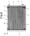
- Fig.6 shows the visual appearance state of the heat exchanger
- Fig.7 shows a cross-section taken on line VII-VII in Fig.6.
- a heat exchanger 1 two upper and lower side plates 4 and 4 are provided between a pair of tube-shaped headers 2 and 3 (left-side header 2 and right-side header 3) made of aluminum, and both ends of the side plates are inserted into the left-side header 2 and the right-side header 3 respectively and braze joined.
- a plurality of tubes 5 are arranged between the side plates 4 and 4, and the both ends of the tubes 5 are braze joined with the left-side header 2 and the right-side header 3 respectively. Refrigerant is caused to run through the inside of the tubes 5. Corrugated fins 6 are braze joined between each tube 5, and the fins 6 are formed by a thin plate made of aluminum.
- an inlet pipe 7 for refrigerant gas through which the interior of the right-side header 3 is filled with refrigerant gas.
- the interior of the right-side header 3 is partitioned into two parts, up and down, by a partition plate 8, and an outlet pipe 9 for discharging refrigerant liquid is provided in the lower part of the right-side header 3.
- the inlet pipe 7 is connected to a compressor (not shown) and the outlet pipe 9 is connected to an evaporator (not shown).
- the refrigerant gas compressed by a compressor (not shown) is supplied into the upper part (above the partition plate 8) of the right-side header 3 through the inlet pipe 7, and flows inside the plurality of tubes 5. While the refrigerant gas is flowing inside the tube 5, air is caused to flow between the fins 6 by a fan (not shown) to cool the fins 6.
- the refrigerant gas inside the tubes 5 is heat-exchanged (cooled) by the fins 6 to be liquefied, and flows into the left-side header 2.
- the refrigerant inside the left-side header 2 flows on the right side in Fig.6 inside the plurality of tubes 5 below to be cooled by the fins 6 again, and is completely liquefied to flow below (below the partition plate 8) the right-side header 3.
- the refrigerant liquid which has flowed below the right-side header 3 is discharged to the evaporator (not shown) through the outlet pipe 9.
- the both ends of the side plate 4 are adapted to be braze joined after they are installed to the left-side header 2 and the right-side header 3 in a predetermined state respectively.
- one end portion of the side plate 4 is inserted into a slit hole 10 in the left-side header 2 as shown in Fig.7 for being braze welded.
- the other end portion of the side plate 4 is also installed to the right-side header 3 in the same manner.
- both ends of the side plate 4 are adapted to be installed to the left-side header 2 and the right-side header 3 in a predetermined state by inserting the end portion of the side plate 4 into the slit hole 10 in the left-side header 2 (right-side header 3).
- the width of the slit hole 10 is set to be larger than the width of the end portion of the side plate 4, there arises a clearance between the slit hole 10 and the end portion of the side plate 4.
- the occurrence of the clearance causes errors to angles of installing the side plate 4 to the left-side header 2 and the right-side header 3, and particularly to the positions of the inlet pipe 7 and the outlet pipe 9 of the right-side header 3. This causes obstruction to the piping of the heat exchanger 1, and if the errors are great, there has been a possibility that the heat exchanger 1 could not be assembled.
- the depth in inserting the end portion of the side plate 4 is not regulated, if the side plate 4 is inserted deep in one header, for example, the left-side header 2 side, the depth of insertion on the right-side header 3 side will become exceedingly small, possibly leading to incomplete fixation even if braze welded.
- the present invention has been achieved in the light of the above-described state of affairs, and is aimed to provide a heat exchanger capable of installing the side plate to the header without errors and accurately.
- the structure according to the present invention is characterized in that in a heat exchanger, in which both ends of the side plates are inserted into the end portions of a pair of headers respectively, a large number of tubes are provided between the pair of headers between the respective side plates, and fins are arranged between the large number of tubes, position regulating means for regulating the inserted state of the side plate into the header is provided between the pair of headers and the both end portions of the side plates respectively.
- the position regulating means is characterized by being a pair of pawls formed by a bent portion of the side plates and provided on both sides of both end portions of the side plate respectively, for pinching the header wall therebetween.
- the position regulating means are characterized by comprising pawls formed by a bent portion of the side plates and provided on both sides of both end portions of the side plate respectively, for abutting on the inner wall of the header, and a convex portion provided in the middle of both sides of both end portions of the side plate, for abutting on the outer wall of the header to pinch the header wall with the pawls.
- the structure according to the present invention is further characterized in that in a heat exchanger, in which a pair of side plates have first and second end portions, respectively; a pair of headers connected to the first and second end portions of the side plates, respectively; a plurality of tubes provided between the pair of side plates and the pair of headers; and position regulating means for regulating the connection between the pair of headers and the pair of side plates, wherein:
- the structure according to the present invention is still further characterized in that in a heat exchanger, in which the two pairs of pawls further comprise a first pair of pawls on an inside surface of a wall of each of the pair of headers, respectively, and a second pair of pawls on an outside surface of the wall of each of the pair of headers, respectively, the first and second pairs of pawls pinching the wall of each of the pair of headers therebetween, wherein:
- a heat exchanger 11 As shown in Fig. 1, two upper and lower side plates 14 and 14 are provided between a pair of tube-shaped headers 12 and 13 made of aluminum (left-side header 12 and right-side header 13), and both ends of the side plate 14 are inserted into the left-side header 12 and the right-side header 13 respectively for being braze joined.
- each tube 15 there are arranged a large number of tubes 15, in which refrigerant is caused to run through, and both ends of the tubes 15 are braze joined with the left-side header 12 and the right-side header 13 respectively.
- fins 16 each prepared by bending a thin plate made of aluminum in a corrugated shape are braze joined.
- an inlet pipe 17 for refrigerant gas In the upper part of the right-side header 13, there is provided an inlet pipe 17 for refrigerant gas, and the interior of the right-side header 13 is partitioned into two parts: up and down by a partition plate 18.
- an outlet pipe 19 for discharging refrigerant liquid In the lower part of the right-side header 13, there is provided an outlet pipe 19 for discharging refrigerant liquid.
- the inlet pipe 17 is connected to a compressor (not shown), and the outlet pipe 19 is connected to an evaporator (not shown).
- the refrigerant gas compressed by the compressor (not shown) is supplied into the upper part (above the partition plate 18) of the right-side header 13 through the inlet pipe 17, and flows inside the plurality of tubes 15. While the refrigerant gas is flowing inside the tubes 15, air is caused to flow between the fins 16 by a fan (not shown) to cool the fins 16.
- the refrigerant gas inside the tubes 15 is heat exchanged (cooled) by the fins 16 to be liquefied, and flows into the left-side header 12.
- the refrigerant inside the left-side header 12 flows to the right in Fig.1 inside a plurality of tubes 15 below to be cooled by the fins 16 again, and is completely liquefied to flow below the right-side header 13 (below the partition plate 18).
- the refrigerant liquid which has flowed below in the right-side header 13 is discharged into an evaporator (not shown) through the outlet pipe 19.
- the both ends of the side plate 14 are inserted into the slit hole 20 in the left-side header 12 (right-side header 13) for being braze welded. Since the positional relationship between both ends of the side plate 14 and the slit holes 20 is regulated by the position regulating means, the side plate 14 can be installed to the left-side header 12 and the right-side header 13 without errors.
- both ends of the side plate 14 there are formed a pair of pawls 21a and 21b as the position regulating means respectively.
- the respective pair of pawls 21a and 21b on both sides are bent to pinch the pipe walls of the left-side header 12 and the right-side header 13 therebetween respectively.
- the pipe wall is pinched at two places on both sides of both end portions of the side plate 14.
- the angles of installation of the side plate 14 to the left-side header 12 and the right-side header 13 are regulated by pinching the pipe wall between the pair of pawls 21a and 21b at two places at each end portion.
- the insertion depth of the side plate 14 to the slit hole 20 is regulated by pinching the pipe wall between the pair of pawls 21a and 21b at two places of each end portion. This enables the side plate 14 to be installed to the left-side header 12 and the right-side header 13 in a state free from errors.
- the upper and lower side plates 14 are installed to the left-side header 12 and the right-side header 13 using the pair of pawls 21a and 21b, and the tubes 15 and the fins 16 are installed, and then they are placed in an oven for being braze joined to constitute a heat exchanger 11.
- the angles of installation and the insertion depth of the side plate 14 to the left-side header 12 and the right-side header 13 are regulated by pinching the pipe wall between the pair of pawls 21a and 21b at two places of each end portion of the side plate 14. Therefore, it is not necessary to confirm the insertion depth, but the input pipe 17 and the outlet pipe 19 can be accurately positioned in a state free from any improper joining. Accordingly, the improper joining will be eliminated, and no obstruction will be caused to the piping in the heat exchanger 11.
- FIG.4 shows a state in which one end portion of the side plate 14 has been inserted into the slit hole 20
- Fig.5 shows a cross-section taken on line V-V in Fig.4.
- Fig.4 corresponds to Fig.2
- Fig.5 corresponds to Fig.3
- the relationship between the right-side header 13 and the side plate 14 is omitted as in the same way in Figs.2 and 3.
- both sides of both end portions of the side plate 14 there are formed pawls 31 and 31 as position regulating means respectively.
- a convex portion 32 as position regulating means respectively.
- the left-side header 12 and the right-side header 13 are interposed between three points: pawls 31 and 31 at two places provided on both sides of both end portions of the side plate 14 respectively and the convex portion 32.
- the angles of installation of the side plate 14 to the left-side header 12 and the right-side header 13 are regulated by pinching the pipe wall between three points: pawls 31 and 31 at two points of each end portion and the convex portion 32.
- the insertion depth of the side plate 14 into the slit hole 20 is regulated by pinching the pipe wall between three points: pawls 31 and 31 at two points of each end portion and the convex portion 32. This causes the side plate 14 to be installed to the left-side header 12 and the right-side header 13 in a state free from errors.
- the position regulating means for regulating the inserted state of the side plate 14 into the left-side header 12 and the right-side header 13 is not limited to such position regulating means as shown in Fig.2 or Fig.5, but it is also possible, for example, to provide the slit 20 side with pawls and to provide the side plate 14 side with cut-outs, holes or the like in which the pawls fit so as to regulate the inserted state of the side plate 14 into the left-side header 12 and the right-side header 13 by the fitting of the two.
- a heat exchanger of the present invention in a heat exchanger in which both end portions of the side plate are inserted into the end portions of a pair of headers respectively, a large number of tubes are provided between the pair of headers, between the respective side plates, and fins are arranged between the large number of tubes, the position regulating-means for regulating the inserted state of the side plate into the header are provided between the pair of headers and both end portions of the side plates. Therefore, the inserted state of the side plate into the header is regulated by the position regulating means. As a result, it becomes possible to accurately install the side plate to the headers in a state free from improper joining and errors, and the headers are accurately positioned, thus eliminating any possibility of causing obstruction to the piping or the like.
- the position regulating means is composed of a pair of pawls provided on both sides of both end portions of the side plate respectively, for pinching the header wall therebetween; and is composed of pawls provided on both sides of both end portions of the side plate respectively, for abutting on the inner wall of the header, and a convex portion provided in the middle between both sides of both end portions of the side plate for abutting on the outer wall of the header to pinch the header wall with the pawls, therefore, it is possible to regulate the inserted state of the side plate into the header with extremely simple structure without increasing the number of parts.
Landscapes
- Engineering & Computer Science (AREA)
- Physics & Mathematics (AREA)
- Thermal Sciences (AREA)
- Mechanical Engineering (AREA)
- General Engineering & Computer Science (AREA)
- Details Of Heat-Exchange And Heat-Transfer (AREA)
- Heat-Exchange Devices With Radiators And Conduit Assemblies (AREA)
- Air-Conditioning For Vehicles (AREA)
Applications Claiming Priority (3)
| Application Number | Priority Date | Filing Date | Title |
|---|---|---|---|
| JP143587/97 | 1997-06-02 | ||
| JP9143587A JPH10332293A (ja) | 1997-06-02 | 1997-06-02 | 熱交換器 |
| JP14358797 | 1997-06-02 |
Publications (3)
| Publication Number | Publication Date |
|---|---|
| EP0882940A2 true EP0882940A2 (de) | 1998-12-09 |
| EP0882940A3 EP0882940A3 (de) | 1998-12-23 |
| EP0882940B1 EP0882940B1 (de) | 2002-12-11 |
Family
ID=15342210
Family Applications (1)
| Application Number | Title | Priority Date | Filing Date |
|---|---|---|---|
| EP98109289A Expired - Lifetime EP0882940B1 (de) | 1997-06-02 | 1998-05-20 | Wärmetauscher |
Country Status (9)
| Country | Link |
|---|---|
| US (1) | US6012513A (de) |
| EP (1) | EP0882940B1 (de) |
| JP (1) | JPH10332293A (de) |
| KR (1) | KR100313634B1 (de) |
| CN (1) | CN1201134A (de) |
| AU (1) | AU709669B2 (de) |
| CA (1) | CA2238917A1 (de) |
| DE (1) | DE69810010T2 (de) |
| TW (1) | TW409177B (de) |
Cited By (6)
| Publication number | Priority date | Publication date | Assignee | Title |
|---|---|---|---|---|
| DE20005523U1 (de) * | 2000-03-28 | 2001-08-16 | Autokühler GmbH & Co KG, 34369 Hofgeismar | Wärmeaustauscher |
| EP1391676A2 (de) | 2002-08-17 | 2004-02-25 | Modine Manufacturing Company | Wärmeaustauscher und Verfahren zur Herstellung |
| US7395853B2 (en) | 2004-10-01 | 2008-07-08 | Delphi Technologies, Inc. | Heat exchanger assembly for a motor vehicle |
| EP2085734A1 (de) * | 2008-01-30 | 2009-08-05 | Huixin Xu | Koordinative Struktur zwischen Rückhaltelaschen auf den Seitenplatten und den Kühlrippen eines Automobilheizkörpers |
| EP1420222A4 (de) * | 2001-07-19 | 2009-08-05 | Showa Denko Kk | Wärmetauscher |
| EP1623178A4 (de) * | 2003-04-28 | 2012-04-25 | Showa Denko Kk | Seitenplatte für wärmetauscher, wärmetauscher und verfahren zur herstellung des wärmetauschers |
Families Citing this family (11)
| Publication number | Priority date | Publication date | Assignee | Title |
|---|---|---|---|---|
| JP2000304490A (ja) * | 1998-12-15 | 2000-11-02 | Calsonic Kansei Corp | 熱交換器のコア部構造および熱交換器のコア部組付方法 |
| DE60100617T2 (de) | 2000-10-06 | 2004-06-09 | Visteon Global Technologies, Inc., Dearborn | Herstellung eines Rohres für einen Wärmetauscher |
| KR20040017323A (ko) * | 2001-07-19 | 2004-02-26 | 쇼와 덴코 가부시키가이샤 | 열 교환기 |
| ES2300548T3 (es) * | 2003-01-17 | 2008-06-16 | Behr France Hambach S.A.R.L. | Transmisor termico con un soporte. |
| CN100513980C (zh) * | 2004-09-15 | 2009-07-15 | 贝洱两合公司 | 用于散热器的侧板 |
| US7594327B2 (en) * | 2005-04-11 | 2009-09-29 | Modine Manufacturing Company | Heat exchanger and method of making the same |
| US7784530B2 (en) * | 2005-09-01 | 2010-08-31 | Showa Denko K.K. | Heat exchanger |
| US8915294B2 (en) * | 2011-03-04 | 2014-12-23 | Denso International America, Inc. | Heat exchanger end cap |
| FR2991037B1 (fr) * | 2012-05-24 | 2014-06-20 | Valeo Systemes Thermiques | Echangeur de chaleur a collecteur renforce |
| JP6583071B2 (ja) * | 2015-03-20 | 2019-10-02 | 株式会社デンソー | タンク、および熱交換器 |
| US10208879B2 (en) * | 2016-05-31 | 2019-02-19 | A. Raymond Et Cie | Fluid connector assembly |
Family Cites Families (13)
| Publication number | Priority date | Publication date | Assignee | Title |
|---|---|---|---|---|
| FR2639099B1 (fr) * | 1988-11-14 | 1990-12-14 | Valeo Chausson Thermique | Echangeur de chaleur, comprenant au moins une joue rapportee sur une de ses faces laterales, notamment radiateur de refroidissement, et procede de realisation d'un tel echangeur |
| JPH02102850U (de) * | 1989-02-01 | 1990-08-15 | ||
| US5052479A (en) * | 1989-06-29 | 1991-10-01 | Yuugen Kaisha Marunaka Seisakusho | Tube for coolant condenser |
| JP2513332Y2 (ja) * | 1990-02-22 | 1996-10-02 | サンデン株式会社 | 熱交換器 |
| JPH0459426A (ja) * | 1990-06-29 | 1992-02-26 | Showa Alum Corp | 熱交換器 |
| JPH04244596A (ja) * | 1991-01-30 | 1992-09-01 | Mitsubishi Heavy Ind Ltd | 熱交換器 |
| JP2537507Y2 (ja) * | 1991-03-08 | 1997-06-04 | サンデン株式会社 | 熱交換器 |
| DE4120869A1 (de) * | 1991-06-25 | 1993-01-07 | Behr Gmbh & Co | Waermetauscher, insbesondere wasser/luft-kuehler fuer verbrennungskraftmaschinen von fahrzeugen |
| JP3063361B2 (ja) * | 1992-03-04 | 2000-07-12 | 株式会社デンソー | 冷凍サイクル用凝縮器 |
| US5289873A (en) * | 1992-06-22 | 1994-03-01 | General Motors Corporation | Heat exchanger sideplate interlocked with header |
| US5327959A (en) * | 1992-09-18 | 1994-07-12 | Modine Manufacturing Company | Header for an evaporator |
| JPH07120189A (ja) * | 1993-10-28 | 1995-05-12 | Nippondenso Co Ltd | 熱交換器 |
| JP3353475B2 (ja) * | 1994-07-28 | 2002-12-03 | 株式会社デンソー | 熱交換器 |
-
1997
- 1997-06-02 JP JP9143587A patent/JPH10332293A/ja not_active Withdrawn
-
1998
- 1998-05-20 EP EP98109289A patent/EP0882940B1/de not_active Expired - Lifetime
- 1998-05-20 DE DE69810010T patent/DE69810010T2/de not_active Expired - Fee Related
- 1998-05-22 AU AU68015/98A patent/AU709669B2/en not_active Ceased
- 1998-05-28 CA CA002238917A patent/CA2238917A1/en not_active Abandoned
- 1998-05-28 TW TW087108352A patent/TW409177B/zh not_active IP Right Cessation
- 1998-05-29 CN CN98109394A patent/CN1201134A/zh active Pending
- 1998-06-01 KR KR1019980020193A patent/KR100313634B1/ko not_active Expired - Fee Related
- 1998-06-01 US US09/088,078 patent/US6012513A/en not_active Expired - Fee Related
Non-Patent Citations (1)
| Title |
|---|
| None |
Cited By (7)
| Publication number | Priority date | Publication date | Assignee | Title |
|---|---|---|---|---|
| DE20005523U1 (de) * | 2000-03-28 | 2001-08-16 | Autokühler GmbH & Co KG, 34369 Hofgeismar | Wärmeaustauscher |
| EP1420222A4 (de) * | 2001-07-19 | 2009-08-05 | Showa Denko Kk | Wärmetauscher |
| EP1391676A2 (de) | 2002-08-17 | 2004-02-25 | Modine Manufacturing Company | Wärmeaustauscher und Verfahren zur Herstellung |
| US6971445B2 (en) | 2002-08-17 | 2005-12-06 | Modine Manufacturing Company | Heat exchanger and method of production |
| EP1623178A4 (de) * | 2003-04-28 | 2012-04-25 | Showa Denko Kk | Seitenplatte für wärmetauscher, wärmetauscher und verfahren zur herstellung des wärmetauschers |
| US7395853B2 (en) | 2004-10-01 | 2008-07-08 | Delphi Technologies, Inc. | Heat exchanger assembly for a motor vehicle |
| EP2085734A1 (de) * | 2008-01-30 | 2009-08-05 | Huixin Xu | Koordinative Struktur zwischen Rückhaltelaschen auf den Seitenplatten und den Kühlrippen eines Automobilheizkörpers |
Also Published As
| Publication number | Publication date |
|---|---|
| CN1201134A (zh) | 1998-12-09 |
| DE69810010D1 (de) | 2003-01-23 |
| DE69810010T2 (de) | 2003-09-04 |
| JPH10332293A (ja) | 1998-12-15 |
| KR19990006546A (ko) | 1999-01-25 |
| AU709669B2 (en) | 1999-09-02 |
| AU6801598A (en) | 1998-12-03 |
| CA2238917A1 (en) | 1998-12-02 |
| EP0882940B1 (de) | 2002-12-11 |
| EP0882940A3 (de) | 1998-12-23 |
| US6012513A (en) | 2000-01-11 |
| KR100313634B1 (ko) | 2002-02-19 |
| TW409177B (en) | 2000-10-21 |
Similar Documents
| Publication | Publication Date | Title |
|---|---|---|
| EP0882940B1 (de) | Wärmetauscher | |
| US5450896A (en) | Two-piece header | |
| EP0532794B1 (de) | Verteiler- und Wärmetauscheranordnung Verteiler- und Wärmetauscheranordnung | |
| US5348083A (en) | Heat exchanger | |
| US5082051A (en) | Heat exchanger having a corrosion prevention means | |
| JPH10238991A (ja) | 熱交換器 | |
| EP0646759B1 (de) | Wärmetauscher | |
| US5094293A (en) | Heat exchanger | |
| EP0590306A1 (de) | Steuerung eines Verfahrens und einer Vorrichtung zum Verpacken in Beutel | |
| US5265672A (en) | Heat exchanger | |
| US5749412A (en) | Heat exchanger having a tubular header with a fastening lug | |
| EP1158261B1 (de) | Leitungsstruktur für Wärmetauscher, Leitungsverbindungsblock für Wärmetauscher und Wärmetauscher mit einem solchen Verbindungsblock | |
| US20070062215A1 (en) | Condenser | |
| US7311138B2 (en) | Stacking-type, multi-flow, heat exchangers and methods for manufacturing such heat exchangers | |
| JP5002796B2 (ja) | 熱交換器 | |
| JPH09113177A (ja) | 凝縮器 | |
| US5620046A (en) | Heat exchanger, particularly a refrigerant evaporator | |
| EP4682453A1 (de) | Wärmetauscher und klimaanlage damit | |
| KR100230434B1 (ko) | 열교환기 | |
| JP3136220B2 (ja) | パラレルフロー熱交換器 | |
| JP4663434B2 (ja) | 熱交換器 | |
| JP2015121344A (ja) | 熱交換器 | |
| JPH08219680A (ja) | 熱交換器 | |
| CN112739972A (zh) | 用于散热器应用的顺应性b型管 | |
| KR19990019825A (ko) | 공조장치의 열교환기 및 그 제조방법 |
Legal Events
| Date | Code | Title | Description |
|---|---|---|---|
| PUAI | Public reference made under article 153(3) epc to a published international application that has entered the european phase |
Free format text: ORIGINAL CODE: 0009012 |
|
| PUAL | Search report despatched |
Free format text: ORIGINAL CODE: 0009013 |
|
| 17P | Request for examination filed |
Effective date: 19980619 |
|
| AK | Designated contracting states |
Kind code of ref document: A2 Designated state(s): DE NL SE |
|
| AX | Request for extension of the european patent |
Free format text: AL;LT;LV;MK;RO;SI |
|
| AK | Designated contracting states |
Kind code of ref document: A3 Designated state(s): AT BE CH CY DE DK ES FI FR GB GR IE IT LI LU MC NL PT SE |
|
| AX | Request for extension of the european patent |
Free format text: AL;LT;LV;MK;RO;SI |
|
| AKX | Designation fees paid |
Free format text: DE NL SE |
|
| 17Q | First examination report despatched |
Effective date: 20000616 |
|
| GRAG | Despatch of communication of intention to grant |
Free format text: ORIGINAL CODE: EPIDOS AGRA |
|
| GRAG | Despatch of communication of intention to grant |
Free format text: ORIGINAL CODE: EPIDOS AGRA |
|
| GRAH | Despatch of communication of intention to grant a patent |
Free format text: ORIGINAL CODE: EPIDOS IGRA |
|
| GRAH | Despatch of communication of intention to grant a patent |
Free format text: ORIGINAL CODE: EPIDOS IGRA |
|
| GRAA | (expected) grant |
Free format text: ORIGINAL CODE: 0009210 |
|
| AK | Designated contracting states |
Kind code of ref document: B1 Designated state(s): DE NL SE |
|
| REF | Corresponds to: |
Ref document number: 69810010 Country of ref document: DE Date of ref document: 20030123 |
|
| PLBE | No opposition filed within time limit |
Free format text: ORIGINAL CODE: 0009261 |
|
| STAA | Information on the status of an ep patent application or granted ep patent |
Free format text: STATUS: NO OPPOSITION FILED WITHIN TIME LIMIT |
|
| 26N | No opposition filed |
Effective date: 20030912 |
|
| PGFP | Annual fee paid to national office [announced via postgrant information from national office to epo] |
Ref country code: NL Payment date: 20040505 Year of fee payment: 7 |
|
| PGFP | Annual fee paid to national office [announced via postgrant information from national office to epo] |
Ref country code: SE Payment date: 20040506 Year of fee payment: 7 |
|
| PGFP | Annual fee paid to national office [announced via postgrant information from national office to epo] |
Ref country code: DE Payment date: 20040527 Year of fee payment: 7 |
|
| PG25 | Lapsed in a contracting state [announced via postgrant information from national office to epo] |
Ref country code: SE Free format text: LAPSE BECAUSE OF NON-PAYMENT OF DUE FEES Effective date: 20050521 |
|
| PG25 | Lapsed in a contracting state [announced via postgrant information from national office to epo] |
Ref country code: NL Free format text: LAPSE BECAUSE OF NON-PAYMENT OF DUE FEES Effective date: 20051201 Ref country code: DE Free format text: LAPSE BECAUSE OF NON-PAYMENT OF DUE FEES Effective date: 20051201 |
|
| EUG | Se: european patent has lapsed | ||
| NLV4 | Nl: lapsed or anulled due to non-payment of the annual fee |
Effective date: 20051201 |