EP0884394A2 - Dispositif pour confiner echantillon et réactifs sur une lamelle lors de réactions PCR in situ - Google Patents
Dispositif pour confiner echantillon et réactifs sur une lamelle lors de réactions PCR in situ Download PDFInfo
- Publication number
- EP0884394A2 EP0884394A2 EP98115093A EP98115093A EP0884394A2 EP 0884394 A2 EP0884394 A2 EP 0884394A2 EP 98115093 A EP98115093 A EP 98115093A EP 98115093 A EP98115093 A EP 98115093A EP 0884394 A2 EP0884394 A2 EP 0884394A2
- Authority
- EP
- European Patent Office
- Prior art keywords
- slide
- assembly
- cover
- retaining assembly
- post
- Prior art date
- Legal status (The legal status is an assumption and is not a legal conclusion. Google has not performed a legal analysis and makes no representation as to the accuracy of the status listed.)
- Granted
Links
Images




Classifications
-
- G—PHYSICS
- G01—MEASURING; TESTING
- G01N—INVESTIGATING OR ANALYSING MATERIALS BY DETERMINING THEIR CHEMICAL OR PHYSICAL PROPERTIES
- G01N1/00—Sampling; Preparing specimens for investigation
- G01N1/28—Preparing specimens for investigation including physical details of (bio-)chemical methods covered elsewhere, e.g. G01N33/50, C12Q
- G01N1/30—Staining; Impregnating ; Fixation; Dehydration; Multistep processes for preparing samples of tissue, cell or nucleic acid material and the like for analysis
- G01N1/31—Apparatus therefor
- G01N1/312—Apparatus therefor for samples mounted on planar substrates
-
- B—PERFORMING OPERATIONS; TRANSPORTING
- B01—PHYSICAL OR CHEMICAL PROCESSES OR APPARATUS IN GENERAL
- B01J—CHEMICAL OR PHYSICAL PROCESSES, e.g. CATALYSIS OR COLLOID CHEMISTRY; THEIR RELEVANT APPARATUS
- B01J19/00—Chemical, physical or physico-chemical processes in general; Their relevant apparatus
- B01J19/0046—Sequential or parallel reactions, e.g. for the synthesis of polypeptides or polynucleotides; Apparatus and devices for combinatorial chemistry or for making molecular arrays
-
- B—PERFORMING OPERATIONS; TRANSPORTING
- B01—PHYSICAL OR CHEMICAL PROCESSES OR APPARATUS IN GENERAL
- B01L—CHEMICAL OR PHYSICAL LABORATORY APPARATUS FOR GENERAL USE
- B01L3/00—Containers or dishes for laboratory use, e.g. laboratory glassware; Droppers
- B01L3/50—Containers for the purpose of retaining a material to be analysed, e.g. test tubes
- B01L3/508—Rigid containers without fluid transport within
-
- B—PERFORMING OPERATIONS; TRANSPORTING
- B01—PHYSICAL OR CHEMICAL PROCESSES OR APPARATUS IN GENERAL
- B01L—CHEMICAL OR PHYSICAL LABORATORY APPARATUS FOR GENERAL USE
- B01L7/00—Heating or cooling apparatus; Heat insulating devices
- B01L7/52—Heating or cooling apparatus; Heat insulating devices with provision for submitting samples to a predetermined sequence of different temperatures, e.g. for treating nucleic acid samples
-
- C—CHEMISTRY; METALLURGY
- C12—BIOCHEMISTRY; BEER; SPIRITS; WINE; VINEGAR; MICROBIOLOGY; ENZYMOLOGY; MUTATION OR GENETIC ENGINEERING
- C12Q—MEASURING OR TESTING PROCESSES INVOLVING ENZYMES, NUCLEIC ACIDS OR MICROORGANISMS; COMPOSITIONS OR TEST PAPERS THEREFOR; PROCESSES OF PREPARING SUCH COMPOSITIONS; CONDITION-RESPONSIVE CONTROL IN MICROBIOLOGICAL OR ENZYMOLOGICAL PROCESSES
- C12Q1/00—Measuring or testing processes involving enzymes, nucleic acids or microorganisms; Compositions therefor; Processes of preparing such compositions
- C12Q1/68—Measuring or testing processes involving enzymes, nucleic acids or microorganisms; Compositions therefor; Processes of preparing such compositions involving nucleic acids
- C12Q1/6813—Hybridisation assays
- C12Q1/6841—In situ hybridisation
-
- C—CHEMISTRY; METALLURGY
- C12—BIOCHEMISTRY; BEER; SPIRITS; WINE; VINEGAR; MICROBIOLOGY; ENZYMOLOGY; MUTATION OR GENETIC ENGINEERING
- C12Q—MEASURING OR TESTING PROCESSES INVOLVING ENZYMES, NUCLEIC ACIDS OR MICROORGANISMS; COMPOSITIONS OR TEST PAPERS THEREFOR; PROCESSES OF PREPARING SUCH COMPOSITIONS; CONDITION-RESPONSIVE CONTROL IN MICROBIOLOGICAL OR ENZYMOLOGICAL PROCESSES
- C12Q1/00—Measuring or testing processes involving enzymes, nucleic acids or microorganisms; Compositions therefor; Processes of preparing such compositions
- C12Q1/68—Measuring or testing processes involving enzymes, nucleic acids or microorganisms; Compositions therefor; Processes of preparing such compositions involving nucleic acids
- C12Q1/6844—Nucleic acid amplification reactions
- C12Q1/686—Polymerase chain reaction [PCR]
-
- B—PERFORMING OPERATIONS; TRANSPORTING
- B01—PHYSICAL OR CHEMICAL PROCESSES OR APPARATUS IN GENERAL
- B01J—CHEMICAL OR PHYSICAL PROCESSES, e.g. CATALYSIS OR COLLOID CHEMISTRY; THEIR RELEVANT APPARATUS
- B01J2219/00—Chemical, physical or physico-chemical processes in general; Their relevant apparatus
- B01J2219/00274—Sequential or parallel reactions; Apparatus and devices for combinatorial chemistry or for making arrays; Chemical library technology
- B01J2219/00718—Type of compounds synthesised
- B01J2219/0072—Organic compounds
- B01J2219/00722—Nucleotides
-
- B—PERFORMING OPERATIONS; TRANSPORTING
- B01—PHYSICAL OR CHEMICAL PROCESSES OR APPARATUS IN GENERAL
- B01L—CHEMICAL OR PHYSICAL LABORATORY APPARATUS FOR GENERAL USE
- B01L2200/00—Solutions for specific problems relating to chemical or physical laboratory apparatus
- B01L2200/06—Fluid handling related problems
- B01L2200/0684—Venting, avoiding backpressure, avoid gas bubbles
-
- B—PERFORMING OPERATIONS; TRANSPORTING
- B01—PHYSICAL OR CHEMICAL PROCESSES OR APPARATUS IN GENERAL
- B01L—CHEMICAL OR PHYSICAL LABORATORY APPARATUS FOR GENERAL USE
- B01L2200/00—Solutions for specific problems relating to chemical or physical laboratory apparatus
- B01L2200/06—Fluid handling related problems
- B01L2200/0689—Sealing
-
- B—PERFORMING OPERATIONS; TRANSPORTING
- B01—PHYSICAL OR CHEMICAL PROCESSES OR APPARATUS IN GENERAL
- B01L—CHEMICAL OR PHYSICAL LABORATORY APPARATUS FOR GENERAL USE
- B01L2300/00—Additional constructional details
- B01L2300/04—Closures and closing means
- B01L2300/041—Connecting closures to device or container
-
- B—PERFORMING OPERATIONS; TRANSPORTING
- B01—PHYSICAL OR CHEMICAL PROCESSES OR APPARATUS IN GENERAL
- B01L—CHEMICAL OR PHYSICAL LABORATORY APPARATUS FOR GENERAL USE
- B01L2300/00—Additional constructional details
- B01L2300/08—Geometry, shape and general structure
- B01L2300/0809—Geometry, shape and general structure rectangular shaped
- B01L2300/0822—Slides
-
- B—PERFORMING OPERATIONS; TRANSPORTING
- B01—PHYSICAL OR CHEMICAL PROCESSES OR APPARATUS IN GENERAL
- B01L—CHEMICAL OR PHYSICAL LABORATORY APPARATUS FOR GENERAL USE
- B01L2300/00—Additional constructional details
- B01L2300/18—Means for temperature control
- B01L2300/1805—Conductive heating, heat from thermostatted solids is conducted to receptacles, e.g. heating plates, blocks
- B01L2300/1827—Conductive heating, heat from thermostatted solids is conducted to receptacles, e.g. heating plates, blocks using resistive heater
-
- B—PERFORMING OPERATIONS; TRANSPORTING
- B01—PHYSICAL OR CHEMICAL PROCESSES OR APPARATUS IN GENERAL
- B01L—CHEMICAL OR PHYSICAL LABORATORY APPARATUS FOR GENERAL USE
- B01L2300/00—Additional constructional details
- B01L2300/18—Means for temperature control
- B01L2300/1838—Means for temperature control using fluid heat transfer medium
- B01L2300/185—Means for temperature control using fluid heat transfer medium using a liquid as fluid
-
- B—PERFORMING OPERATIONS; TRANSPORTING
- B01—PHYSICAL OR CHEMICAL PROCESSES OR APPARATUS IN GENERAL
- B01L—CHEMICAL OR PHYSICAL LABORATORY APPARATUS FOR GENERAL USE
- B01L9/00—Supporting devices; Holding devices
- B01L9/52—Supports specially adapted for flat sample carriers, e.g. for plates, slides, chips
-
- C—CHEMISTRY; METALLURGY
- C40—COMBINATORIAL TECHNOLOGY
- C40B—COMBINATORIAL CHEMISTRY; LIBRARIES, e.g. CHEMICAL LIBRARIES
- C40B40/00—Libraries per se, e.g. arrays, mixtures
- C40B40/04—Libraries containing only organic compounds
- C40B40/06—Libraries containing nucleotides or polynucleotides, or derivatives thereof
-
- Y—GENERAL TAGGING OF NEW TECHNOLOGICAL DEVELOPMENTS; GENERAL TAGGING OF CROSS-SECTIONAL TECHNOLOGIES SPANNING OVER SEVERAL SECTIONS OF THE IPC; TECHNICAL SUBJECTS COVERED BY FORMER USPC CROSS-REFERENCE ART COLLECTIONS [XRACs] AND DIGESTS
- Y10—TECHNICAL SUBJECTS COVERED BY FORMER USPC
- Y10S—TECHNICAL SUBJECTS COVERED BY FORMER USPC CROSS-REFERENCE ART COLLECTIONS [XRACs] AND DIGESTS
- Y10S435/00—Chemistry: molecular biology and microbiology
- Y10S435/809—Incubators or racks or holders for culture plates or containers
Definitions
- This invention generally relates to a system for performing the polymerase chain reaction (PCR) and more particularly to an apparatus and method for performing PCR on a DNA or RNA sample without removing it from its original cell structure.
- PCR polymerase chain reaction
- PCR polymerase chain reaction
- the polymerase chain reaction is a process for making a very large number of faithful copies of a segment of double-stranded DNA (amplifying) by thermally cycling one or more molecules of this DNA (the template DNA) in the presence of thermally stable DNA polymerase enzyme, (typically Taq polymerase), the four DNA nucleotide bases and two or more single-stranded DNA primers.
- thermally stable DNA polymerase enzyme typically Taq polymerase
- These primers are short segments of the order of 20 bases that are complementary to the 5' ends of the two complementary DNA single strands which make up the double-stranded template.
- PCR is an enormous valuable technique which is very widely practiced, and has revolutionized the field of molecular biology.
- the technique is disclosed in detail in U.S. Patent Nos. 4,683,195, 4,683,202, and 4,965,188.
- the reaction has until recently been carried out in solution in small reaction vessels, where the DNA to be amplified is in suspension.
- Apparatus for this process is disclosed in U.S. Patent No. 5,038,852 and in U.S. Patent Application No. 07/871,274, filed April 20, 1992.
- in situ PCR PCR-in situ PCR.
- the cells may be individual cells, or part of a tissue sample. Most often, in situ PCR is performed on cells or thin slices of tissue mounted on microscope slides. The cells or tissue usually have been fixed by treatment with formalin, or other reagents so that their morphology is preserved and recognizable after treatment.
- the selected DNA segment is amplified in such a way that the amplified product DNA can be selectively stained
- microscopic examination of the PCR treated cells can identify which cells in a tissue sample, if any, contain the specific DNA segment, and even where within the cell it is located.
- Visualization of the amplified DNA within the cells can be achieved by either of two methods.
- One method uses a complementary single stranded DNA probe to which a label molecule has been attached. This probe is hybridized to the specific DNA sequences in the amplified sample, if there are any, and the excess probe and label is washed away. Then the locations of the remaining label molecules are rendered visible by treatment with developer reagents. This technique for visualization is called " in situ hybridization", or "indirect detection" of the in situ amplified DNA.
- the other method of visualization is to use, during the PCR process, a PCR reagent which includes modified DNA nucleotide bases to which a label molecule has been attached. Many modified bases carrying label molecules will be directly incorporated into the amplified product by the DNA polymerase. The location of the amplified DNA can then be visualized by treating the slide as before with developer reagents. This method is called "direct incorporation detection" of DNA amplified in situ .
- the developer reagents in both methods typically include an enzyme such as alkaline phosphatase coupled to a molecule which binds strongly and specifically to the label molecule on the amplified DNA or on the hybridized probe, and a substrate which the enzyme converts into an insoluble, strongly absorbing dye.
- an enzyme such as alkaline phosphatase coupled to a molecule which binds strongly and specifically to the label molecule on the amplified DNA or on the hybridized probe
- a substrate which the enzyme converts into an insoluble, strongly absorbing dye.
- the label molecule on the amplified DNA is biotin
- the binding molecule coupled to the enzyme
- the binding molecule is typically avidin.
- the label molecule is digoxigenin
- the binding molecule is an anti-digoxigenin antibody.
- Both kinds of developing reagents have been used in both indirect detection by in situ hybridization and in direct incorporation detection.
- the labels on the label molecules may be colored, fluorescent, or radioactive.
- Both methods of detection of in situ amplified DNA can be very sensitive, detecting from ten to a few hundred copies of the amplified DNA segment in each cell. Both require some post-PCR processing of the slide after the in situ PCR thermal cycling has been completed.
- Cytospins are amplified identically to tissues mounted on slides.
- tissue sections When cells in tissue sections are to be studied, they must be amplified directly upon a surface, because the thin sections otherwise cannot display the tissue's morphology.
- the main problems associated with thermal cycling of these tissues are to maintain tissue morphology as well as cell morphology, inhibit evaporation of the PCR reaction mixture over the sample, and to obtain uniform, robustly repeatable results.
- the area of the slide with the specimen to be amplified must be covered with an excess of the PCR reagent containing DNA polymerase enzyme, nucleotides, primers and other components at correct concentrations. Then the slide and reagents must be cycled typically 10 to 30 times between temperatures typically near 95°C and 68°C, but sometimes as low as 37°C, spending at least a fraction of a minute or more at each of two or three selected temperatures during each cycle.
- a "chemical hot start" in a PCR can be achieved is by including, in the reagent, a heat-labile component such as single strand binding protein (SSB) which prevents any extension by the polymerase enzyme until the reaction mixture has been heated in the first PCR cycle to a temperature high enough to prevent non-specific hybridization and also to destroy the heat-labile SSB component.
- a heat-labile component such as single strand binding protein (SSB) which prevents any extension by the polymerase enzyme until the reaction mixture has been heated in the first PCR cycle to a temperature high enough to prevent non-specific hybridization and also to destroy the heat-labile SSB component.
- Another way to implement a chemical hot start is to replace the dUTP with Uracil and to add to the reagent the heat-labile enzyme UNG (Uracil-N-Glycosylase) which destroys any PCR products made during a low temperature incubation prior to the first PCR cycle.
- a still further way of implementing a chemical hot start is to combine the Taq polymerase enzyme with a Taq antibody before adding it to the reagent.
- a Taq monoclonal antibody has recently been announced by Dr. John Findlay of Kodak Clinical Products Division in a paper entitled “Development of PCR for In Vitro Diagnostics” presented at the 1992 San Diego Conference: Genetic Recognition, held November 18-20, 1992.
- the Taq antibody binds to the Taq polymerase enzyme and inhibits its function at normal temperatures. However, upon heating the inhibited Taq polymerase to near 95°C, the Taq antibody, a normal protein, is denatured, releasing the Taq polymerase enzyme and allowing it to function normally in the PCR process.
- Nuovo et al, American Journal of Pathology 139 , #6, 1239-1244 (1992) covered the samples with a coverslip made from flexible, temperature-stable polypropylene.
- the coverslip was typically anchored over the desired tissue section with a drop of nail polish at one corner.
- the slide is typically placed in an aluminum "boat” placed upon the sample block of a Perkin-Elmer Cetus DNA Thermal Cycler. This "boat” mainly serves the function to hold the mineral oil that was later added to the slide assembly to prevent evaporation of the reagents.
- the temperature of the sample was typically raised to about 65°, and the coverslip partially lifted to allow for the introduction of Taq DNA polymerase into the reaction mixture to initiate the PCR reaction.
- Another methodology employed to thermal cycle and reduce evaporation and condensation problems is to place slides within plastic bags and thermal cycle them in an air-oven type thermal cycler.
- Staskus et al, Microbial Pathogenesis 1991 , 11, 67-76 (1991) and Emberto et al, Proc. Natl. Acad. Sci. U.S.A. 90, 357-361 (1993) covered tissues with a coverslip and then mineral oil before placing the slides in a heat sealable plastic pouch cycled in an air-oven thermal cycler.
- the air oven approach avoids the possible problem of evaporation of water from the sample condensing on the cover slip because the entire assembly is roughly isothermal during thermal cycling.
- none of the existing methods incorporate all the desirable aspects of good thermal uniformity, evaporation control without mineral oil, small reagent volume, maintenance of cell morphology, the ability to do hot starts, and convenience for assembling large numbers of slides for thermal cycling a position other than horizontal.
- Almost everyone today uses immersion of the prepared slide in mineral oil to prevent evaporation of water from the reagent during thermal cycling.
- oil overlay is a major inconvenience because usually it must be carefully and completely removed by additional steps after thermal cycling and before subsequent processing with detection reagents. Oil is also sometimes a carrier of contaminants which can kill the PCR.
- the present invention described below meets the above needs.
- the containment system in accordance with the present invention comprises a conventional glass slide having mounted thereon a tissue sample containing a target nucleic acid, a flexible cover member over the sample, and a retainer assembly mechanically fastened to the slide for retaining a reagent against the sample on the slide beneath the cover member.
- the reagent is contained in contact with the selected portion of the sample specimen by a thin, compliant cover which is clamped mechanically to the slide.
- This cover may be opaque or transparent as the reagent will preferably be viewed through the glass during assembly rather than through the cover, and must be inert to the PCR reagents and sample.
- a generally circular seal ring around the perimeter of the cover presses the cover against the slide to maintain the hermetic seal. Pressure is maintained by a spring clip and cross beam arrangement.
- the amplified sample on the slide will be viewed in a conventional manner through a microscope after the cover and its retainer have been removed.
- the system makes assembly of the complete reaction on the slide quick, convenient and repeatable and requires minimal skill.
- the assembly procedure is easily compatible with physical hot starts.
- the system of the invention is compatible with conventional microscopic detection techniques.
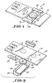
- Figure 1 is a perspective view of a sample containment system assembly in accordance with the invention.
- Figure 2 is an exploded view of the system assembly shown in Figure 1, shown upside down, the way it is assembled.
- Figure 3 is an enlarged partial top view of the assembly shown in Figure 1, shown upside down.
- Figure 4 is a sectional view of the assembly taken along the line 4-4 in Figure 3.
- Figure 5 is a cross sectional view of the assembly taken along the line 5-5 in Figure 3.
- Figure 6 is an end view of one of the spring clips in accordance with the invention.
- Figure 7 is a top view of the spring clip shown in Figure 6.
- Figure 8 is a bottom view of a preferred cross beam used in the assembly in accordance with the invention.
- Figure 9 is a side view of the cross beam shown in Figure 8.
- Figure 10 is a cross sectional view of the cross beam in Figure 8 taken along the line 10-10.
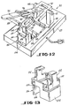
- Figure 11 is a perspective view of a manual assembly fixture for the containment system of the invention.
- Figure 12 is a perspective view of a mechanical assembly apparatus for the containment system in accordance with the present invention.
- Figure 13 is a perspective view of the plier assembly separated from the apparatus of Figure 12.
- Figure 14 is a top view of a grooved adapter plate for an existing thermal cycler.
- Figure 15 is a sectional view of the grooved adapter plate shown in Figure 14.
- Figure 16 is a perspective view of a thermal cycler having a modified heat exchanger block adapted to receive the sample containment systems in accordance with the present invention.
- Figure 17 is an enlarged partial sectional view of the heat exchanger block of the thermal cycler shown in Figure 16.
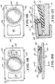
- Figure 18 is a top view of a first alternative embodiment of the cross beam and cover in accordance with the invention.
- Figure 19 is a top view of a second alternative embodiment of the cross beam and cover in accordance with the invention.
- Figure 20 is a sectional view of the assembled containment system in accordance with the invention incorporating an alternative cross beam and the alternative cover shown in Figures 18 and 19.
- Figure 21 is an enlarged partial sectional view of the containment system shown in Figure 20 taken along the line 21-21.
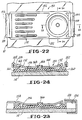
- Figure 22 is a top view of a containment system assembled to a slide in accordance with the invention utilizing a third alternative preferred embodiment of the cross beam and cover.
- Figure 23 is a partial sectional view of the invention shown in Figure 22 taken on the line 23-23.
- Figure 24 is a partial sectional view of the invention shown in Figure 22 taken along the line 24-24.
- the containment system 10 for retaining a sample specimen 12 containing a target nucleic acid and a reagent 13 on the sample 12 mounted on a glass slide 14, in accordance with the invention, is shown in Figure 1.
- the system 10 comprises the glass slide 14, a generally compliant cover member 16 over the sample 12, and a retaining assembly 18 fastening the cover 16 to the slide 14.
- FIG. 1 shows an exploded view of the individual parts, and Figure 3 shows an enlarged top view of the assembled system shown in Figure 1.
- Figures 4 and 5 show cross-sections of the system 10 shown in Figure 3.
- the reagent 13, about one drop, is sealed into the volume between the cover member 16 and the slide 14 by a compliant seal member or gasket around its perimeter.
- the seal member may be a separate piece or may be an integral part of the cover 16.
- the seal is preferably the compliant rim portion 19 of the cover member 16 which is made of an elastomer which is chemically compatible with the PCR reagents. In the preferred embodiment, it is made of silicone rubber. It is wide enough, and compressed with sufficient force per unit area by a rigid seal ring 20 against the slide 14 so that even when the slide's surface under the seal ring is covered with a thin layer of cells or tissue of the sample 12, very little water, liquid or vapor, can escape from the space beneath the cover 16 during thermal cycling. The gasket seal is still maintained even at boiling temperature conditions.
- the compliant cover 16 is shaped so that, when relaxed, it is gently concave on the side touching the reagent.
- the degree of concavity is chosen to define the volume of reagent 13 that will be contained between the cover 16 and the slide when the seal ring 20 presses the rim portion 19 of the cover 16 against the slide 14.
- the volume is chosen as follows. If the volume is too large, the amount of reagent 13 required will be unnecessarily expensive, and will take a little longer to heat and cool.
- the interesting area of the sample 12 to be examined is no larger than 10mm in diameter.
- the clear area of the slide is about 25mm by 57mm since one end is usually frosted for labeling. Since it is quite difficult to deposit a tissue section only a few microns thick precisely at a pre-selected location on the slide, it is desirable to make the cover 16 capable of being located anywhere in the clear area. Also, there may be more than one interesting area on a slide, so it is an advantage to be able to mount more than one sample and system 10 on a slide, as shown in Figure 1.
- the new retaining assembly 18 for clamping the cover 16 to the slide 14 permits a widely variable location for the cover 16. Samples located anywhere within a margin of a few millimeters of the edges of the clear area of the slide can be contained and amplified. The few millimeters margin is needed for the seal ring 20.
- the rim portion 19 of the cover 16 is reinforced by the rigid seal ring 20 around its perimeter such that if the seal ring 20 at two opposite edges of the cover is compressed against the slide 14 to make an adequate seal, then the seal will be adequate at all other parts of the perimeter of the cover.
- the rigid seal ring 20 thus constrains the perimeter of the cover to remain in one plane.
- the cover 16 is preferably a circular disk of thin rubber sheet.
- the rigid seal ring 20 is a stainless steel ring bonded to the rim 19 of the rubber cover 16.
- the ring 20 may have a rectangular, trapezoidal, triangular or other polygonal cross sectional shape so there is at least one flat side for bonding with the cover 16. Most preferably, the ring 20 has a rectangular or trapezoidal cross sectional shape. A "D" shape cross section would also be permissible.
- the ring need not be round. It may be oblong or other continuous shape so long as the cover 16 can be sealed to the slide surface.
- the rim 19 of the rubber disk cover 16 which is bonded to the steel ring 20 thus forms a gasket which is continuous with the rest of the disk.
- the thin rubber sheet cover 16 be impervious to the diffusion of water vapor through it and at the same time not hostile to the PCR reagents. Silicone rubber, though not hostile to PCR, is too permeable to water vapor. Accordingly, either a sandwich or composite of a non-hostile elastomer such as silicone rubber and a non-permeable elastomer such as polypropylene, or a non-hostile coating or layer 21 such as Parylene C from Union Carbide on at least the underside of a non-permeable elastomer layer may be preferable as a cover material as indicated in Figures 4 and 5.
- a non-hostile elastomer such as silicone rubber and a non-permeable elastomer such as polypropylene
- a non-hostile coating or layer 21 such as Parylene C from Union Carbide on at least the underside of a non-permeable elastomer layer may be preferable as a cover material as indicated in Figures 4
- the necessary concave shape of the cover 16 can be achieved during molding or by deforming the flat sheet cover 16 while it is being bonded to the rigid ring 20, or by attaching the center of the outside surface of the cover 16 to a cross-piece attached to the ring 20 (not shown) to hold the center of the disk slightly out of the plane of the ring 20.
- the cover 16 is held against the slide 14 by a rigid cross beam 22 with parallel rails 24 which touch only opposite portions of the seal ring 20.
- the rails 24 of the beam 22 extend across the slide from one long edge to the other.
- the cover 16 can be located anywhere on the cross beam 22, as shown in Figure 3.
- the cross beam 22 can be clamped to the slide anywhere along the slide's length. Therefore, in the present invention, the cover 16 can be placed anywhere within the clear area of the slide.
- the rails 24 of the cross beam 22 preferably have an L-shaped cross section as shown in Figure 5 to enhance rigidity.
- the rails 24 are joined by flat ends 26 which are clamped to the slide 14 by two clips 28 as shown in Figures 1, 3, and 4. These clips 28 each extend over the long edges to the back side 30 of the slide 14, the side opposite to that carrying the sample 12.
- Each end 26 of the cross beam 22 is slightly bent to form an inclined plane. As the clips 28 are pushed into place, they slide on these inclined plane ends 26 and apply substantial compressive force on the cross beam 22 and the seal ring 20 to compress the rim portion 19 of the cover 16 and against the slide 14.
- the clips 28 and the cross beam 22 may be made of relatively thin material, probably stainless steel, they are sufficiently rigid so that, during the assembly, they flex very little.
- the stored energy that sustains the clamping force preferably comes largely from compression of the rubber gasket (the rim 19 of the cover 16 beneath the seal ring 20), not from flexure of the cross beam 22 or clips 28.
- the beneficial consequence of this is that no matter where the cover 16 is located on the slide 14, the rails 24 of the cross beam 22 are always parallel to the slide and the rim 19 is compressed the same amount, uniformly around its entire perimeter.
- the cross beam 22 and clips 28 clamping the cover 16 to the slide 14 are also sufficiently rigid to resist the pressure increase caused by heating the reagent 13 to nearly boiling temperature.
- cover 16 is compliant greatly reduces the maximum pressure that can occur beneath the cover.
- compliant cover 16 resists fluidic expansion during heating without breaking the slide 14 which effectively pressurizes the enclosed volume. This may prevent or at least minimize bubble formation in this reagent 13 during thermal cycling, making use of the containment system of the invention independent.
- the clip 28 is a piece of stainless steel sheet metal bent into a "J" shape to form a long side 32, and a short side 34, and a connecting perpendicular side 36.
- Side 32 may have a pair of dimples 38 protruding toward short side 34. These dimples 38 are spaced so as to engage and snap over and engage the inside edge of the inclined plane end 26 of the cross beam 22 to latch the clip 28, the cross beam 22, and slide 14 together as shown in Figures 1 and 4.
- the function of the dimples 38 may be performed by a raised ridge or other interference mechanism between the mating retaining assembly 18 parts.
- the cross beam 22a is generally a stamped rectangular sheet metal body with a rectangular opening forming two parallel rails 24a joined by transverse ends 26a.
- the rails 24a of the cross beam 22a have an L-shaped cross section as shown in Figure 10.
- ends 26a join with rails 24a in a double bend 27a.
- the double bend 27a permits the long leg of the clip 28 to frictionally engage with the surface of end 26a. This double bend 27a also creates almost a step so that the overall thickness of the assembled slide and cover assembly is minimized when the clip 28 is installed.
- the cover 16 is no larger than necessary, the volume of reagent required is no more than necessary, and the force necessary to make a leak-tight seal with the seal ring is also minimized. All of these attributes are advantageous. It is desirable to not need great sealing force because it makes assembly easier, and the mechanism necessary to rigidly sustain a larger force would make the assembly unnecessarily thick and massive. This, in turn will limit the number of slides which can be accommodated simultaneously in a cycler if they are mounted on edge. It would also increase the thermal time-constant of the assembly, and slow the cycling process.
- Assembly of the complete containment system 10 on a slide 14 with reagent 13 in place under the cover 16 is accomplished by a unique procedure which is also part of the present invention.
- a manual assembly fixture 40 is used. This fixture 40 is shown in Figure 11.
- a mechanically assisted assembly fixture or tool is used. Such a tool is shown in Figure 12.
- the manual assembly fixture 40 shown in Figure 11 basically consists of an assembly post 42 fixed to a base 45 and a slide guide 44 movably mounted on the base 45.
- the slide guide 44 is spring biased upward so as to move vertically around the post 42.
- the top of the post 42 has recessed areas 46 and 48 that are shaped to loosely receive the clips 28 and the cross beam 22 to hold them in position for assembly to the slide 14.
- the post 42 also has a central air passage 43.
- the slide guide 44 is a U-shaped body which has two generally flat tray portions 50 positioned adjacent opposite sides of the post 42. These tray portions 50 have a channel sized to receive a standard microscope slide. The two tray portions 50 are connected together by an integral U-shaped yoke 52. Each tray portion 50 has a sleeve 54 fixed to its underside which slides over a mating pin 56 fixed to the base 45. Springs 58 mounted around the pins 56 bias the guide upward to a position in which a slide 14 held by the tray portions 44 will be positioned above the recessed areas 46 and 48 in the top of the post 42.
- Assembly of the containment system 10 is as follows. First the two clips 28 are placed in recessed areas 46 on top of the assembly post 42 with their long sides 32 down against the post 42. They are then positioned so that the space between their facing short sides 34 is just a little wider than the width of a standard 1 inch microscope slide. Next, the cross beam 22 is placed on the assembly post in between the depressions 46 with its rail edges upward as in Figure 2 and the rails 24 in the recessed areas 48. The dimensions of the various parts are such that a portion of each of the inclined planes formed by the ends 26 of the cross beam 22 lie on top of the long sides 32 of the clips 28. Thus, the initial engagement of the clips 28 with the cross beam 22 is first established.
- a pre-assembled combination of the cross beam 22 and two clips 28, held in the initially engaged and appropriately spaced relationship by a weak adhesive can be provided to reduce the amount of manipulation necessary to prepare the assembly 18.
- the clips 28 are made of magnetic stainless steel, then small permanent magnets, embedded in the assembly post, could automatically position the clips properly with minimal manipulation.
- the cover 16, with seal ring 20 attached to the rim portion 19, is placed on and between the rails 24 of the cross beam 22 with the concave, gasket side of the cover 16 up and the seal ring 20 resting on the rails 24 of the cross beam 22.
- the cover 16 is then positioned such that it is centered under the area of interest (containing the sample) on the slide 14.
- the cover's dimensions are such that its rim 19, i.e. the gasket or seal surface, projects above the rails of the cross beam 22 by more than the amount that the gasket will be compressed when assembled, so that even after the rim 19 is compressed, the cross beam 22 will preferably not actually touch the glass slide 14, as is shown in Figures 4 and 5.
- a droplet of reagent 13 is then placed on the cover 16.
- a pipet set to deliver the desired reagent volume is preferably used, by hand, to deliver the reagent as a droplet close to the center of the concave surface. Since the cover's surface is only partially wettable, the droplet does not spread significantly. It also stands up well above the rim 19 of the cover 16.
- the slide 14, having at least one specimen sample 12 previously fixed thereto, is then placed on the slide guide 44 of the assembly fixture 40 with the sample side down, directly over the droplet of reagent 13.
- the slide guide 44 is initially positioned so that the bottom of the slide is always held at least a few millimeters above the top of the reagent droplet 13 by springs 58.
- the slide 14 is positioned by sliding it in its long direction so as to center the sample area to be processed over the droplet on the cover 16. This can be done by looking through the back of the slide 14 (which is now on top). It is made especially easy if, as is common practice, the area of interest is circled with a china-marker on the back 30 of the slide 14.
- the user places a finger (gloved) on the back 30 of the slide 14 directly over the assembly post 42 and presses directly down with enough force to overcome the upward-pushing springs 58 and move the slide guide 44 down.
- This causes the sample side of the slide 14 to make contact with the reagent droplet 13 and forces the droplet 13 to spread out over the slide 14 and the cover surface within the rim 19.
- the volume of the reagent droplet has been chosen to be slightly larger than the volume between the concave surface of the cover 16 and a plane touching its rim 19 (the slide surface). Therefore the droplet 13 reaches and passes over the edge of the rim 19 just before the slide surface makes contact with the rim 19.
- the back side 30 of the slide 14 should be just at or below the bottom edge of the short side 34 of each of the clips 28.
- the operator uses the (gloved) thumb and finger of his other hand to squeeze the two clips 28 toward each other, over the edges of the slide 14, and over the ends 26 of the cross beam 22, until the clips 28 stop with their vertical connecting sides 36 against the edges of the slide 14. This action completes the compression of the rim 19 of the cover 16.
- the clips 28 stay in place until intentionally removed because of the small detents 38 that engage the ends 26 of the cross beam 22, and/or because the tangent of the angle of the inclined plane on each of the cross beam ends 26 is smaller than the coefficient of friction between the clip 28 and the cross beam end 26.
- the volume trapped between the slide 14 and the cover 16 is entirely filled with incompressible reagent liquid 13.
- the cover 16 is preferable for the cover itself to be compliant, so that it can expand to accommodate the fixed reagent volume without a large increase in pressure, which otherwise would make assembly difficult.
- Another reason why the cover 16 should be compliant is that when the reagent 13 is heated to a temperature approaching or beyond its boiling point, it expands, its vapor pressure rises, and gases dissolved in it tend to come out of solution. If the cover were not at all compliant, the pressure within it might rise enough to break the slide or the cover seal and cause loss of reagent.
- a mechanically assisted assembly apparatus or tool 80 is shown in Figure 12. This tool is similar to the tool shown in Figure 11 except that handling the assembly with fingers is virtually eliminated. This tool 80 is preferred, especially if physical hot starts (described in detail below) are to be implemented.
- the tool 80 shown in Figure 12 has a base 45 and a post 42 mounted thereon as in Figure 11 and utilizes a slide guide 82 somewhat similar in shape to the guide 44 shown in Figure 11.
- tool 80 has a compression arm 84 and a clip installation mechanism 86 so that the user does not have to physically touch a hot component of a retaining assembly 18 during the assembly operation.
- the slide guide 82 has a pair of spaced flat tray portions 88 sized to receive a slide 14.
- the tray portions are joined by an integral, U-shaped yoke 90, which rotates about a horizontal pivot pin 92.
- Pivot pin 92 is horizontally supported above the base 45 by two fixed supports 94 at about the same height as the top of the post 42.
- One end of the compression arm 84 is also pivotally mounted inside the yoke 90 on pin 92.
- Arm 84 is a flat, elongated member with a generally rectangular opening 96 positioned over the top of the post 42 which receives and supports the cross beam 22 and clips 28.
- the opening 96 permits observation of the cover member 16, cross beam 22, and sample 12 on the slide 14 as the arm 84 is lowered over post 42 onto the slide 14.
- a rubber cushion pad 98 encircling opening 96 is used to preclude slide breakage when the arm 94 is pressed against the slide 14.
- the arm 94 is preferably spring biased upward to keep it raised out of the way until needed.
- the slide guide 82 is spring biased upward to keep the slide 14 above the cross beam 22, clips 28, cover member 16, and reagent drop 13 until the arm 94 is lowered for final installation of the retaining assembly 18 to the slide 14.
- Both the arm 84 and the slide guide 82 may have conventional springs (not shown) mounted on pin 90 or the springs may extend from the base 45 to provide the desired upward bias.
- the clip installation mechanism 86 is preferably a pair of spring loaded pliers 100 mounted on the post 42 having two opposing fingers 102 each bent toward a recessed area 46 which positions a clip 28 adjacent the edge of the slide 14 mounted in the guide 82, and an integral opposing handle portions 104.
- the opposing handle portions 104 of the pliers 100 are manually squeezed together to push the clips 28 onto the sides of the slide over the slide edges and the ends 26 of the cross beam 22 to complete assembly of the containment system 10.
- Each plier 100 is pivotally mounted on a stationary pivot pin 106 which projects through the side of the post 42, directly under the point of contact between the fingers 102 and clips 28.
- Each L-shaped finger 102 has a short leg which fits into one of the recessed areas 46 in the top of the post 42.
- Each flat handle portion 104 wraps around two adjacent sides of the post 42.
- a spring (not shown) positioned between each handle portion 104 and the post 42 (not shown) biases the handle portions 104 and finger portions 102 of the pliers 100 outward to permit installation of the retaining clips 28 in the recesses 46.
- the tips 102 move toward each other, forcing the clips 28 onto the slide 14.
- the tool 80 is operated as follows. Two clips 28 are installed in the recesses 46 as previously described.
- the cross member 22, seal ring 20, cover 16, and reagent 13 are placed sequentially on the post 42 and
- a slide 14 with a sample 12 mounted thereto is then placed in the tray portion 88 of the guide 82 with the sample side down and the sample positioned vertically above the reagent 13 in the cover 16.
- the compression arm 84 is then pivoted downward against the slide to lower the slide 14 onto the cover 16 and spread the reagent and enzyme over the sample on the slide 14.
- the arm 94 is fully lowered, the pliers 100 are squeezed, moving the fingers 102 toward each other, pushing the retaining clips 28 onto the slide 14 and cross beam ends 26.
- the complete slide assembly 10 is then removed from the tool 80, placed in a modified thermal cycler, and thermally cycled as above described.
- the assembly post 42 is made with a vertical bore or air passage 43 through it which at the bottom communicates with ambient air.
- An internal thermostatically controlled heater when turned on, keeps the body of the post 42 at about 75°C, which is hotter than the hot start temperature, approximately 70°C.
- This heater may be a resistance coil wrapped around the central bore 43 or may simply be embedded in the base 45 or in the post 42. Fins on the interior of the bore 43 may be provided to help heat the air rising in the vertical passage. Convection maintains a rising column of hot air, as in a chimney, which bathes the cross beam 22 and cover 16 mounted on the top of the post 42 prior to final assembly.
- the cross beam 22 and clips 28 are also heated by contact with the metal assembly post 42.
- the slides 14 to be processed are stored in a heated carrier that maintains them at about 75°C.
- the clips 28, covers 16, and cross beams 22 can be stored in small heated containers at the work station, and handled with tweezers.
- the time required to mount two pre-heated clips, a cross beam and a cover onto the heated assembly post 42 might typically be 10 to 15 seconds.
- the time to transfer pre-heated reagent 13, using a pre-heated positive displacement pipette tip, is less than 10 seconds.
- the heated reagent 13 needs to be exposed no more than another 10 seconds before the pre-heated slide is pushed down to seal it and fasten the components of the retention assembly 18 together. A few seconds later the assembled slide can be back in its heated carrier, never having been cooler than 70°C. Concentration of the reagent by evaporation should thus be minimal because the exposure time is so short.
- a true physical hot start is achievable merely by heating the assembly tool and storing the slides, containment parts, reagent, and pipette tips in heated carriers at the assembly work station. No other change in procedure is necessary. This procedure is simplified with the use of the assembly tool 80 shown in Figure 12 since the storage of heated components and contact with the heated components and guide 82 is obviated. Pre-assemblies of clips 28 and cross beams 22 could also be used for hot starts if the components are attached together by an adhesive that is strong at ambient temperatures, facilitating packaging and shipment, but weakens at the hot start temperature for easy, final assembly.
- the clips 28 of the containment system 10 overhang the edges of the slide 14 and occupy a few millimeters of its back side 30. Because of this, the flat heat exchanging surface of any thermal cycler which is used with the new containment system must be provided with grooves which are slightly less than 1mm deep and 3mm wide to accommodate the clips 28.
- An existing thermal cycler such as the Perkin Elmer DNA Thermal Cycler, the Perkin Elmer Model 480, or the Perkin Elmer Model 9600 may be utilized to thermally cycle slide assemblies in accordance with the present invention if an adapter plate is placed on the flat upper surface of the thermal cycler block.
- an adapter plate 110 is shown in top and sectional views in Figures 14 and 15.
- This plate 110 has a flat bottom surface 112 and top surface 114 which has spaced parallel grooves 116. These grooves 116 are sized to receive clips 28 so that the flat surface portion 118 between the grooves 116 fully contacts the glass surface of the slide 14 placed on the adapter plate.
- the adapter plate 110 may be designed to accommodate up to 3 or 4 slide assemblies.
- a heat conductive liquid such as an oil or thermally conductive grease is preferably spread on the upper surface portion 118 to increase the thermal contact across the interface between the back side 30 of the slide 14 and the flat heat exchange surface 118 between the grooves 116.
- a silicone grease or mineral oil should also be used between the thermal cycler block and the adapter plate 110 to ensure good thermal contact across this interface.
- Ethylene glycol or its polymers can also be used advantageously to provide the good thermal contact between both interfaces. Ethylene glycol or its polymers have the advantage of being water soluble, thus simplifying the cleansing of assembly components and the thermal cycler block.
- Another advantage of using either oil, grease, or ethylene glycol or its polymers between the slides and the adapter plate and between the thermal cycler block and the adapter plate is that the liquid layer acts as a suction clamp to retain the slides to the adapter plate and the adapter plate in place on the block, thus minimizing the chance of droppage during handling.
- the containment system 10 of the invention is adaptable for cycling larger numbers of slides than just discussed because each assembly 10 is less than 4mm thick, may be cycled in any physical position, and does not require submersion in oil.
- the assemblies 10 may be vertically arranged in a modified thermal cycler block to accommodate a greater number of slide assemblies.
- a modified thermal cycler 120 containing a modified metal block 122 is shown in Figure 16.
- the block 122 contains 8 slots 124 which are 10mm apart on centers between metal partitions 126 therebetween. Each slot 124 is about 5mm wide and each partition 126 has a flat vertical heat exchange surface 128 with the necessary pair of grooves 130 for receiving the clips 28 on the right hand side of each metal partition 126.
- Figure 17 is a partial section of the block 182 through a slide assembly 10 mounted on edge in one such slot 124.
- the top edge 132 of the bottom groove 130 is smoothly chamfered to prevent its catching on the clip 28 as the slide 14 is removed vertically.
- the upper groove 130 does not have an upper edge.
- small leaf springs of conventional design may be placed at the ends of each slot 124 to hold the slide gently but firmly against the vertical metal surface 128.
- the springs may be engaged after the slides are loaded and disengaged before their removal or may be permanently mounted in the slots 124 so as to continuously press the slide 14 assembly 10 into engagement with surface 128.
- the assembled slides 10 are removed from their slots 124 for further analysis.
- the containment system parts are easily removed by sliding the clips 28 off of the slide 14. If the containment parts and the slide 14 are dropped into a container of 5% bleach to sterilize them, then later rinsed and dried, they can be reused many times. The limit on reuse will be determined by deterioration of the cover 16 and/or rim 19, a condition that is very easily checked by a visual examination, before or after the cover 16 is clamped to a slide 14.
- contamination with unwanted DNA is far less of a problem with in situ PCR. The reason is that the contaminating DNA does not get inside properly fixed cells. Further, any contaminating DNA is washed away with the reagents, before the development steps after thermal cycling. This fact about in situ PCR makes washable and re-usable parts more acceptable than they would be for PCR in solution.
- the complete in situ PCR system includes the slide and containment system 10, the assembly fixture 40 or 80, a modified thermal cycler designed for one or more slides 14 with the containment assembly 10 attached, and reagents 13 modified as described above.
- the novel and unexpected result of this combination is convenient, robust and sensitive detection and location of specific DNA sequences within cells and tissue specimens.
- the ring 20 may be integrated into the cross beam 22. This will simplify component construction and assembly of the retaining assembly 18 and the containment system 10.
- FIG. 10 Construction of the containment system 10 may be simplified in several ways.
- the cross beam and retaining ring may be integrated.
- FIG 18. A first alternative embodiment of the cross beam and cover in accordance with the invention is illustrated in Figure 18.
- Figure 19. A variation on this alternative cross beam is illustrated in Figure 19.
- Like numbers will be utilized in the following description to describe identical or interchangeable components in the in situ PCR containment system described above.
- FIG. 18 top views of alternative cross beams 120 and 140 are each shown assembled to an alternative cover 122.
- the difference between the cross beams 120 and 140 is simply the placement of the circular aperture 124 and 142.
- the aperture 124 in cross beam 120 is centrally located.
- the aperture 142 in cross beam 140 is located adjacent to one end 144 of the cross beam 140.
- the combination of the two cross beams 120 and 140 permits the placement of the cover 122 over a sample 12 mounted anywhere on a slide 14 merely by changing the orientation of the cross beam 140 or by choosing the cross beam 120 which has a centrally disposed aperture 124.
- the seal ring is integral with the cross beam.
- Cross beam 120 has a generally circular ring portion 126 which presses on a rim portion 128 of the cover 122 when the containment system 10 is assembled as shown in the partial sectional views of Figures 20 and 21.
- the cross beam 120 is preferably a stamped piece from a sheet of stainless steel.
- the cross beam 120 has a pair of parallel, vertically bent edges forming rails 130 extending between opposite ends 132 which are bent downwardly at a shallow angle of about 3° to receive the clips 134 in a manner similar to clips 28 in the first embodiment described above. As shown in Figure 21, each clip 134 squeezes the end 132 and glass slide 14 together during installation to compress the rim portion 128 of the cover 122 to the slide 14.
- cover 122 has an annular rib or ridge 136 between the rim portion 128 and the central domed or concave portion 138 under which the reagent mixture 13 is retained.
- This annular ridge 136 preferably has an enlarged bulbous top 137 which snap fits into the aperture 124 retaining the pieces together.
- the cover 122 and the cross beam 120 may be assembled as a separate unit to simplify the final assembly of the components of the containment system 10 of this alternative embodiment as shown in Figure 21.
- the cross beam 120 may have cutout regions 139 which eliminate unnecessary metal material. Alternatively, these cutout regions 139 may be replaced by ribs or corrugations (not shown) to enhance rigidity of the cross beam 120.
- cross beam 140 has parallel raised rail edges 146 and a single cutout area 148 in contrast to the two cutout areas in the cross beam 120.
- the cross beam 140 may be rotated 180° from that shown in Figure 19 for placement on a slide 14 so that the combination of one cross beam 140 and one cross beam 120 permits coverage of practically all potential sample locations on a slide 14.
- Assembly of the alternative containment system 10 as shown in Figures 18-21 is similar to that above described for the first embodiment except that a retaining ring 20 is no longer required and the cover 122 and cross beam 120 are assembled together first.
- the manual or mechanically assisted assembly tools 40 and 80 may be utilized as previously described to assemble the containment system to the slides and perform hot starts.
- FIGs 22 through 24 show a third embodiment of the containment system 10 in accordance with the present invention utilizing another alternative cover and cross beam 150.
- the cross beam 150 in this embodiment shown in a top view in Figure 22, is again a stamped sheet metal piece having parallel raised rails 152 and bent ends 154.
- this embodiment does not have a central aperture through which the central portion of the cover 156 extends.
- an annular trough or depression 158 in the sheet metal cross beam 150 performs the function of the retaining ring 20 in the first embodiment and the ring portion 126 in the second embodiment.
- This annular trough 158 is sized so that the rim portion 160 of the cover 156 is fully engaged with the underside of the trough 158.
- a raised ridge 162 projects upward between the rim portion 160 and a central portion 164 of the cover 156.
- the cover 156 may optionally include a central protrusion or knob 166 which is designed to snap fit into an opening 168 centrally disposed inside the annular trough 158 to retain the cover 156 and cross beam 150 together. If this central protrusion 166 is provided as shown, it is not necessary to provide the ridge 162 on the cover 156. In addition, it is not necessary to mold the cover 156 with a concave central portion 164. The snap fit of the protrusion 166 into the opening 168 pulls the central portion up against the central portion of the cross beam 150 to product the required curvature for accommodating the reagent 13. Although the ridge 162 is not required in this case, the ridge 162 may help define this central curvature.
- the cross beam 150 may also have a plurality of corrugations or ribs 170 as shown in Figure 22, pressed into the sheet metal material to increase the rigidity of the structure so that it can be fabricated of very thin sheet metal material, thus reducing its thermal mass and overall thickness.
- This alternative third embodiment 150 has a distinct advantage over the embodiments previously described.
- the cover material be impervious to diffusion of moisture as well as being non-hostile to the PCR reaction is greatly reduced. Accordingly, this permits a broader selection of materials.
- the cover 156 may be a single molded body of silicone rubber. A composite or sandwich of the silicone rubber with a nonpermeable elastomer such as polypropylene is not required. This feature results because the diffusion of moisture through the central portion 164 of the cover 156 into the closed space 172 quickly reaches equilibrium because the volume is very small. Evaporation can be further minimized by eliminating the optional protrusion 166 and the optional opening 168 shown. If the central knob 166 is eliminated, then the raised ridge 162 may be used to temporarily fasten the cover 156 in place on and under the cross beam 150.
- the void region 172 is necessary, however, to permit displacement of the cover 156 during compression of the rim portion 160 during installation of the clips 28 or 134 to provide the seal to effectively retain the reagent 13 against the sample 12.
- the trapped volume 172 also serves to control the pressure under the cover 156 during thermal cycling. This reduces or may prevent bubble formation in the reagent 13 during incubations at the denaturation temperature near 95°C.
- rails 152 are essentially doubled over edges of the sheet metal piece forming the cross beam 150. This design is relatively rigid and permits use of sheet material of minimal thickness. In addition, the doubled over edges minimize the presence of sharp edges which could be a handling hazard with thin metal materials.
- the ends 154 may also be bent over as are the rails 152 for this same reason.
- the cross beam 150 may have the annular trough 158 centrally disposed to accommodate centrally located samples on the slide 14. This alternative is not illustrated as it is an obvious variation from that shown in Figure 22.
- the cross beams and dips may be made of a rigid plastic material or one of the clips 28 may be made an integral part of one end of the cross beam 22 so that only one clip 28 is needed to fit over the opposite end 26 of the cross beam 22.
- the embodiments of the invention are subject to modification, variation, and change without departing from the proper scope and fair meaning of the appended claims. Accordingly, it is intended to embrace all such changes, modifications, and variations that fall within the spirit and broad scope of the appended claims. All patent applications, patents and other publications cited herein are incorporated by reference in their entirety.
Landscapes
- Chemical & Material Sciences (AREA)
- Health & Medical Sciences (AREA)
- Life Sciences & Earth Sciences (AREA)
- Organic Chemistry (AREA)
- Chemical Kinetics & Catalysis (AREA)
- General Health & Medical Sciences (AREA)
- Engineering & Computer Science (AREA)
- Molecular Biology (AREA)
- Biochemistry (AREA)
- Proteomics, Peptides & Aminoacids (AREA)
- Analytical Chemistry (AREA)
- Wood Science & Technology (AREA)
- Zoology (AREA)
- Clinical Laboratory Science (AREA)
- Immunology (AREA)
- Physics & Mathematics (AREA)
- General Engineering & Computer Science (AREA)
- Bioinformatics & Cheminformatics (AREA)
- Microbiology (AREA)
- Biotechnology (AREA)
- Genetics & Genomics (AREA)
- Biophysics (AREA)
- Biomedical Technology (AREA)
- General Physics & Mathematics (AREA)
- Pathology (AREA)
- Hematology (AREA)
- Apparatus Associated With Microorganisms And Enzymes (AREA)
- Superconductors And Manufacturing Methods Therefor (AREA)
- Transition And Organic Metals Composition Catalysts For Addition Polymerization (AREA)
- Amplifiers (AREA)
- Measuring Or Testing Involving Enzymes Or Micro-Organisms (AREA)
- Investigating Or Analysing Biological Materials (AREA)
- Earth Drilling (AREA)
- Soil Working Implements (AREA)
- Input Circuits Of Receivers And Coupling Of Receivers And Audio Equipment (AREA)
- Analysing Materials By The Use Of Radiation (AREA)
- Sampling And Sample Adjustment (AREA)
Applications Claiming Priority (3)
| Application Number | Priority Date | Filing Date | Title |
|---|---|---|---|
| US17721 | 1993-02-16 | ||
| US08/017,721 US5364790A (en) | 1993-02-16 | 1993-02-16 | In situ PCR amplification system |
| EP93115813A EP0611598B1 (fr) | 1993-02-16 | 1993-09-30 | Procédé d'amplification PCR in situ |
Related Parent Applications (1)
| Application Number | Title | Priority Date | Filing Date |
|---|---|---|---|
| EP93115813A Division EP0611598B1 (fr) | 1993-02-16 | 1993-09-30 | Procédé d'amplification PCR in situ |
Publications (3)
| Publication Number | Publication Date |
|---|---|
| EP0884394A2 true EP0884394A2 (fr) | 1998-12-16 |
| EP0884394A3 EP0884394A3 (fr) | 1998-12-23 |
| EP0884394B1 EP0884394B1 (fr) | 2005-03-23 |
Family
ID=21784183
Family Applications (2)
| Application Number | Title | Priority Date | Filing Date |
|---|---|---|---|
| EP93115813A Expired - Lifetime EP0611598B1 (fr) | 1993-02-16 | 1993-09-30 | Procédé d'amplification PCR in situ |
| EP98115093A Expired - Lifetime EP0884394B1 (fr) | 1993-02-16 | 1993-09-30 | Dispositif pour confiner echantillon et réactifs sur une lamelle lors de réactions PCR in situ |
Family Applications Before (1)
| Application Number | Title | Priority Date | Filing Date |
|---|---|---|---|
| EP93115813A Expired - Lifetime EP0611598B1 (fr) | 1993-02-16 | 1993-09-30 | Procédé d'amplification PCR in situ |
Country Status (12)
| Country | Link |
|---|---|
| US (4) | US5364790A (fr) |
| EP (2) | EP0611598B1 (fr) |
| JP (1) | JPH06245771A (fr) |
| KR (1) | KR100286792B1 (fr) |
| CN (1) | CN1072725C (fr) |
| AT (2) | ATE291635T1 (fr) |
| AU (2) | AU673397B2 (fr) |
| CA (1) | CA2106360A1 (fr) |
| DE (2) | DE69333785T2 (fr) |
| DK (1) | DK0611598T3 (fr) |
| IL (3) | IL120847A (fr) |
| NZ (1) | NZ248835A (fr) |
Cited By (3)
| Publication number | Priority date | Publication date | Assignee | Title |
|---|---|---|---|---|
| WO2001025750A1 (fr) * | 1999-10-07 | 2001-04-12 | Ventana Medical Systems, Inc. | Rechauffeur calibreur et convertisseur de temperature pour lame porte-objet, et procede correspondant |
| WO2009105596A3 (fr) * | 2008-02-21 | 2009-12-17 | George Mason Intellectual Properties, Inc. | Procédés et dispositifs de pré-traitement d'échantillons de tissu |
| CN103952301A (zh) * | 2014-04-11 | 2014-07-30 | 珠海美路得企业发展有限公司 | 一种医学检测设备的加热系统 |
Families Citing this family (192)
| Publication number | Priority date | Publication date | Assignee | Title |
|---|---|---|---|---|
| US7560273B2 (en) * | 2002-07-23 | 2009-07-14 | Applied Biosystems, Llc | Slip cover for heated platen assembly |
| US7081226B1 (en) | 1996-06-04 | 2006-07-25 | University Of Utah Research Foundation | System and method for fluorescence monitoring |
| US5935522A (en) * | 1990-06-04 | 1999-08-10 | University Of Utah Research Foundation | On-line DNA analysis system with rapid thermal cycling |
| US7273749B1 (en) | 1990-06-04 | 2007-09-25 | University Of Utah Research Foundation | Container for carrying out and monitoring biological processes |
| US5587128A (en) | 1992-05-01 | 1996-12-24 | The Trustees Of The University Of Pennsylvania | Mesoscale polynucleotide amplification devices |
| US5843640A (en) * | 1992-06-19 | 1998-12-01 | Northwestern University | Method of simultaneously detecting amplified nucleic acid sequences and cellular antigens in cells |
| US5364790A (en) * | 1993-02-16 | 1994-11-15 | The Perkin-Elmer Corporation | In situ PCR amplification system |
| ATE193465T1 (de) * | 1994-01-06 | 2000-06-15 | Johnson & Johnson Clin Diag | Vorrichtung zum erwärmen einer flüssigkeitsführenden kammer von einer reaktionscuvette |
| GB9402205D0 (en) * | 1994-02-04 | 1994-03-30 | Ray Ronnie A | Enclosed reaction container |
| US5631734A (en) | 1994-02-10 | 1997-05-20 | Affymetrix, Inc. | Method and apparatus for detection of fluorescently labeled materials |
| JP3537194B2 (ja) * | 1994-10-17 | 2004-06-14 | オリンパス株式会社 | 光学顕微鏡 |
| US5721136A (en) * | 1994-11-09 | 1998-02-24 | Mj Research, Inc. | Sealing device for thermal cycling vessels |
| ATE212064T1 (de) * | 1994-11-14 | 2002-02-15 | Univ Pennsylvania | Gerät zur amplifikation von polynukleotiden im mesomassstab |
| US5935825A (en) * | 1994-11-18 | 1999-08-10 | Shimadzu Corporation | Process and reagent for amplifying nucleic acid sequences |
| US5804366A (en) * | 1995-02-09 | 1998-09-08 | Baxter International Inc. | Method and apparatus for sodding microvessel cells onto a synthetic vascular graft |
| WO1996028537A1 (fr) * | 1995-03-09 | 1996-09-19 | University Of Utah Research Foundation | Genes de l'intervalle qt long et procede de diagnostic ou de prevention de l'apparition du syndrome a intervalle qt long |
| US5599673A (en) * | 1995-03-09 | 1997-02-04 | University Of Utah Research Foundation | Long QT syndrome genes |
| US5566021A (en) * | 1995-03-23 | 1996-10-15 | Pettingell; James T. | Microscope stage having a sliding grease interface |
| GB9506312D0 (en) | 1995-03-28 | 1995-05-17 | Medical Res Council | Improvements in or relating to sample processing |
| US6022689A (en) * | 1995-04-07 | 2000-02-08 | University Of New Mexico | Situ hybridization slide processes |
| AU693023B2 (en) * | 1995-05-05 | 1998-06-18 | Applied Biosystems, Llc | Methods and reagents for combined PCR amplification and hybridization probing assay |
| US5604130A (en) * | 1995-05-31 | 1997-02-18 | Chiron Corporation | Releasable multiwell plate cover |
| US20020022261A1 (en) * | 1995-06-29 | 2002-02-21 | Anderson Rolfe C. | Miniaturized genetic analysis systems and methods |
| GB9516636D0 (en) * | 1995-08-14 | 1995-10-18 | Univ London | In-situ nucleic acid amplification and detection |
| EP0790861A1 (fr) * | 1995-09-12 | 1997-08-27 | Becton, Dickinson and Company | Dispositif et procede d'amplification et de dosage d'adn |
| US5963368A (en) * | 1995-09-15 | 1999-10-05 | Accumed International, Inc. | Specimen management system |
| US6091842A (en) * | 1996-10-25 | 2000-07-18 | Accumed International, Inc. | Cytological specimen analysis system with slide mapping and generation of viewing path information |
| US5930732A (en) * | 1995-09-15 | 1999-07-27 | Accumed International, Inc. | System for simplifying the implementation of specified functions |
| US6118581A (en) * | 1995-09-15 | 2000-09-12 | Accumed International, Inc. | Multifunctional control unit for a microscope |
| CA2174279C (fr) * | 1995-09-26 | 2001-01-30 | Francis J. Walker | Enduit d'etancheite pour joints au silicone utilises en automobile |
| WO1997013869A1 (fr) * | 1995-10-10 | 1997-04-17 | The Regents Of The University Of California | Detection de mutations specifiques d'alleles par amplification pcr in situ a transcriptase inverse, specifique d'alleles |
| US6004512A (en) * | 1995-12-08 | 1999-12-21 | Mj Research | Sample cartridge slide block |
| US6114122A (en) | 1996-03-26 | 2000-09-05 | Affymetrix, Inc. | Fluidics station with a mounting system and method of using |
| JPH1052300A (ja) * | 1996-06-03 | 1998-02-24 | Kyowa Hakko Kogyo Co Ltd | 細胞内テロメラーゼ活性の測定法 |
| JP4540754B2 (ja) * | 1996-06-04 | 2010-09-08 | ユニバーシティ オブ ユタ リサーチ ファウンデーション | Pcr中のハイブリダイゼーションのモニタリング |
| US5795748A (en) * | 1996-09-26 | 1998-08-18 | Becton Dickinson And Company | DNA microwell device and method |
| US5882903A (en) * | 1996-11-01 | 1999-03-16 | Sarnoff Corporation | Assay system and method for conducting assays |
| US6703247B1 (en) | 1996-12-23 | 2004-03-09 | American Registry Of Pathology | Apparatus and methods for efficient processing of biological samples on slides |
| US5958341A (en) * | 1996-12-23 | 1999-09-28 | American Registry Of Pathology | Apparatus for efficient processing of tissue samples on slides |
| US5958349A (en) * | 1997-02-28 | 1999-09-28 | Cepheid | Reaction vessel for heat-exchanging chemical processes |
| US6074868A (en) | 1997-03-03 | 2000-06-13 | Regents Of The University Of Minnesota | Alumina plate method and device for controlling temperature |
| US7133726B1 (en) * | 1997-03-28 | 2006-11-07 | Applera Corporation | Thermal cycler for PCR |
| US5939329A (en) * | 1997-05-14 | 1999-08-17 | Serim Research Corporation | Test strip incubation device and method |
| US6567214B2 (en) | 1997-09-04 | 2003-05-20 | Andrew E. Lorincz | Microscope slide having culture media and method for use |
| US5812312A (en) * | 1997-09-04 | 1998-09-22 | Lorincz; Andrew Endre | Microscope slide |
| US6239906B1 (en) | 1997-09-04 | 2001-05-29 | Andrew E. Lorincz | Flexible microscope slide |
| DE19753598C1 (de) * | 1997-12-03 | 1999-07-01 | Micronas Intermetall Gmbh | Vorrichtung zum Messen physiologischer Parameter |
| JP3847559B2 (ja) * | 1998-02-27 | 2006-11-22 | ベンタナ・メデイカル・システムズ・インコーポレーテツド | 独立スライド加熱器を有する自動化分子病理学装置 |
| US20090111101A1 (en) * | 1998-05-09 | 2009-04-30 | Ikonisys, Inc. | Automated Cancer Diagnostic Methods Using FISH |
| US20080241848A1 (en) * | 1998-05-09 | 2008-10-02 | Ikonisys, Inc. | Methods for prenatal diagnosis of aneuploidy |
| US7901887B2 (en) * | 1998-05-09 | 2011-03-08 | Ikonisys, Inc. | Automated cancer diagnostic methods using fish |
| JP2002514762A (ja) * | 1998-05-09 | 2002-05-21 | アイコニシス,インコーポレーテッド | コンピュータによって制御された、胎児細胞を含む希少細胞に基づく診断のための方法および装置 |
| US6180314B1 (en) * | 1998-05-27 | 2001-01-30 | Becton, Dickinson And Company | Method for preparing thin liquid samples for microscopic analysis |
| US6358475B1 (en) * | 1998-05-27 | 2002-03-19 | Becton, Dickinson And Company | Device for preparing thin liquid for microscopic analysis |
| CA2339163C (fr) * | 1998-08-10 | 2010-01-12 | Genomic Solutions, Inc. | Dispositif thermique pour fluide pour l'hybridation d'acides nucleiques |
| USD418228S (en) * | 1998-09-03 | 1999-12-28 | Harry Fisch | Microscope slide assembly |
| US6413780B1 (en) * | 1998-10-14 | 2002-07-02 | Abbott Laboratories | Structure and method for performing a determination of an item of interest in a sample |
| WO2000026415A2 (fr) * | 1998-11-02 | 2000-05-11 | The Brigham & Women's Hospital, Inc. | Technique d'hybridation genomique soustractive |
| US20060216744A1 (en) * | 1998-12-23 | 2006-09-28 | American Registry Of Pathology Armed Forces Institute Of Pathology | Apparatus and methods for efficient processing of biological samples on slides |
| WO2000038838A1 (fr) * | 1998-12-23 | 2000-07-06 | American Registry Of Pathology | Dispositif et procedes servant a traiter efficacement des specimens biologiques sur des microplaquettes |
| ES2520140T3 (es) * | 1999-02-17 | 2014-11-11 | Lucid, Inc. | Portador de muestras de tejido |
| WO2000049392A1 (fr) | 1999-02-17 | 2000-08-24 | Lucid, Inc. | Cassette destinee a faciliter le sectionnement optique d'un prelevement de tissu retenu |
| US6171850B1 (en) | 1999-03-08 | 2001-01-09 | Caliper Technologies Corp. | Integrated devices and systems for performing temperature controlled reactions and analyses |
| US6555361B1 (en) * | 1999-03-24 | 2003-04-29 | Corning Incorporated | Hybridization chamber for high density nucleic acid arrays |
| USD423678S (en) * | 1999-05-26 | 2000-04-25 | Harry Fisch | Microscope slide assembly |
| US6258593B1 (en) * | 1999-06-30 | 2001-07-10 | Agilent Technologies Inc. | Apparatus for conducting chemical or biochemical reactions on a solid surface within an enclosed chamber |
| DE19941905C2 (de) * | 1999-09-02 | 2002-06-06 | Max Planck Gesellschaft | Probenkammer zur Flüssigkeitsbehandlung biologischer Proben |
| USD431301S (en) * | 1999-09-27 | 2000-09-26 | Harry Fisch | Microscope slide assembly |
| USD431300S (en) * | 1999-09-27 | 2000-09-26 | Harry Fisch | Microscope slide assembly |
| DE19948087B4 (de) * | 1999-10-06 | 2008-04-17 | Evotec Ag | Verfahren zur Herstellung eines Reaktionssubstrats |
| US6300124B1 (en) | 1999-11-02 | 2001-10-09 | Regents Of The University Of Minnesota | Device and method to directly control the temperature of microscope slides |
| WO2001032934A2 (fr) * | 1999-11-04 | 2001-05-10 | Arcturus Engineering, Inc. | Station d"hybridation |
| US6309889B1 (en) * | 1999-12-23 | 2001-10-30 | Glaxo Wellcome Inc. | Nano-grid micro reactor and methods |
| WO2001081892A2 (fr) | 2000-04-26 | 2001-11-01 | Arcturus Engineering, Inc. | Dispositif et support de dispositif d'extraction par microdissection laser de capture (« laser capture microdissection »: lcm) et procede de traitement fluidique post-lcm |
| FR2808888B1 (fr) * | 2000-05-15 | 2003-06-20 | Trophos | Dispositif d'observation sequentielle d'echantillons et procedes l'utilisant |
| JP2002010777A (ja) * | 2000-06-30 | 2002-01-15 | Precision System Science Co Ltd | 反応容器、反応装置および反応液の温度制御方法 |
| US6511277B1 (en) * | 2000-07-10 | 2003-01-28 | Affymetrix, Inc. | Cartridge loader and methods |
| US6422249B1 (en) | 2000-08-10 | 2002-07-23 | Affymetrix Inc. | Cartridge washing system and methods |
| US7198924B2 (en) | 2000-12-11 | 2007-04-03 | Invitrogen Corporation | Methods and compositions for synthesis of nucleic acid molecules using multiple recognition sites |
| US6939516B2 (en) * | 2000-09-29 | 2005-09-06 | Becton, Dickinson And Company | Multi-well plate cover and assembly adapted for mechanical manipulation |
| ES2169701B1 (es) * | 2000-12-21 | 2003-11-01 | Univ Jaen | Reactor microcristalografico. |
| JP2002262854A (ja) * | 2001-03-06 | 2002-09-17 | Hitachi Software Eng Co Ltd | ハイブリダイゼーション器具 |
| WO2003015923A1 (fr) * | 2001-08-20 | 2003-02-27 | Biomicro Systems, Inc. | Melange de fluides dans des chambres a faible rapport de forme |
| JP4148778B2 (ja) | 2001-03-09 | 2008-09-10 | バイオミクロ システムズ インコーポレイティッド | アレイとのミクロ流体的インターフェース機器 |
| CA2441163A1 (fr) * | 2001-03-16 | 2002-09-26 | Memorec Biotec Gmbh | Dispositif d'analyse pour analyser des echantillons chimiques et/ou biologiques |
| DE10116938C1 (de) * | 2001-03-30 | 2002-11-07 | Univ Dresden Tech | Zellkammer für die Lichtmikroskopie |
| US6677131B2 (en) * | 2001-05-14 | 2004-01-13 | Corning Incorporated | Well frame including connectors for biological fluids |
| JPWO2002101037A1 (ja) * | 2001-05-31 | 2005-04-07 | 扶桑薬品工業株式会社 | 食細胞機能の評価方法およびその利用 |
| WO2002099133A1 (fr) * | 2001-05-31 | 2002-12-12 | Fuso Pharmaceutical Industries, Ltd. | Procede ameliore de detection et d'identification de micro-organismes causes d'infections |
| US6485918B1 (en) * | 2001-07-02 | 2002-11-26 | Packard Bioscience Corporation | Method and apparatus for incubation of a liquid reagent and target spots on a microarray substrate |
| WO2003093168A2 (fr) * | 2001-07-26 | 2003-11-13 | Motorola, Inc. | Systeme et procedes permettant d'effectuer des melanges dans un dispositif microfluidique |
| WO2003015922A1 (fr) * | 2001-08-20 | 2003-02-27 | Biomicro Systems, Inc. | Dispositif d'interface a microreseaux stratifie |
| US6767733B1 (en) | 2001-10-10 | 2004-07-27 | Pritest, Inc. | Portable biosensor apparatus with controlled flow |
| US6939032B2 (en) * | 2001-10-25 | 2005-09-06 | Erie Scientific Company | Cover slip mixing apparatus |
| US10156501B2 (en) | 2001-11-05 | 2018-12-18 | Life Technologies Corporation | Automated microdissection instrument for determining a location of a laser beam projection on a worksurface area |
| US7943093B2 (en) * | 2001-12-12 | 2011-05-17 | Erie Scientific Company | Cover slip |
| US20040020993A1 (en) * | 2001-12-28 | 2004-02-05 | Green Larry R. | Method for luminescent identification and calibration |
| WO2003066907A1 (fr) * | 2002-02-05 | 2003-08-14 | Genome Therapeutics Corporation | Joint pour plaque a microtitration, et procedes d'utilisation du joint |
| JP2004003989A (ja) | 2002-03-15 | 2004-01-08 | Affymetrix Inc | 生物学的物質の走査のためのシステム、方法、および製品 |
| US20040241723A1 (en) * | 2002-03-18 | 2004-12-02 | Marquess Foley Leigh Shaw | Systems and methods for improving protein and milk production of dairy herds |
| DE10218988C1 (de) * | 2002-04-24 | 2003-11-20 | Horst Dieter Becker | Vorrichtung und Verfahren zum Benetzen von Objekten |
| US20040060987A1 (en) * | 2002-05-07 | 2004-04-01 | Green Larry R. | Digital image analysis method for enhanced and optimized signals in fluorophore detection |
| JP2004028694A (ja) * | 2002-06-24 | 2004-01-29 | Canon Inc | 核酸プローブ・アレイ基板の温度制御装置、及び、これを用いた遺伝子検出方法 |
| KR100855996B1 (ko) * | 2002-07-02 | 2008-09-02 | 유재천 | Pcr 디스크 장치, pcr 디스크 드라이버 장치 및 그를 이용한 분석 방법 |
| ATE526418T1 (de) * | 2002-08-05 | 2011-10-15 | Quanta Biosciences Inc | Verbesserte zusammensetzungen zur in-vitro- amplifikation von nukleinsäuren |
| EP1539209A2 (fr) * | 2002-09-05 | 2005-06-15 | Invitrogen Corporation | Compositions et procedes de synthese d'acides nucleiques |
| US6730883B2 (en) * | 2002-10-02 | 2004-05-04 | Stratagene | Flexible heating cover assembly for thermal cycling of samples of biological material |
| US20040120861A1 (en) * | 2002-10-11 | 2004-06-24 | Affymetrix, Inc. | System and method for high-throughput processing of biological probe arrays |
| US20040101439A1 (en) * | 2002-11-21 | 2004-05-27 | Fusco Adam J | Biological and chemical reaction devices and methods of manufacture |
| EP1606419A1 (fr) | 2003-03-18 | 2005-12-21 | Quantum Genetics Ireland Limited | Systemes et procedes pour accroitre la production de proteines et de lait chez des bovins laitiers |
| WO2004083824A1 (fr) * | 2003-03-20 | 2004-09-30 | Dakocytomation Denmark A/S | Systeme pour etablir un couvercle d'echantillon sur un substrat |
| US7317415B2 (en) | 2003-08-08 | 2008-01-08 | Affymetrix, Inc. | System, method, and product for scanning of biological materials employing dual analog integrators |
| US7517498B2 (en) * | 2003-08-19 | 2009-04-14 | Agilent Technologies, Inc. | Apparatus for substrate handling |
| US20050226779A1 (en) | 2003-09-19 | 2005-10-13 | Oldham Mark F | Vacuum assist for a microplate |
| US20050221358A1 (en) * | 2003-09-19 | 2005-10-06 | Carrillo Albert L | Pressure chamber clamp mechanism |
| DE10352716A1 (de) * | 2003-11-05 | 2005-06-16 | Einsle, Xaver | Plattform |
| WO2005054438A2 (fr) | 2003-12-01 | 2005-06-16 | Invitrogen Corporation | Molecule d'acide nucleique contenant des sites de recombinaison et leurs procedes d'utilisation |
| US7122799B2 (en) * | 2003-12-18 | 2006-10-17 | Palo Alto Research Center Incorporated | LED or laser enabled real-time PCR system and spectrophotometer |
| WO2005064309A1 (fr) * | 2003-12-23 | 2005-07-14 | Ventana Medical Systems, Inc. | Procede et appareil de traitement efficace faisant intervenir un liquide dans une couche mince de surfaces plates |
| WO2005112544A2 (fr) | 2004-02-19 | 2005-12-01 | The Governors Of The University Of Alberta | Polymorphismes du promoteur de la leptine et utilisations correspondantes |
| US20050183976A1 (en) * | 2004-02-19 | 2005-08-25 | Brothers John G. | Cryogenic canister assembly |
| DE102004022263A1 (de) * | 2004-05-06 | 2005-12-15 | Clondiag Chip Technologies Gmbh | Vorrichtung und Verfahren zum Nachweis von molekularen Wechselwirkungen |
| US20050282270A1 (en) * | 2004-06-21 | 2005-12-22 | Applera Corporation | System for thermally cycling biological samples with heated lid and pneumatic actuator |
| US7700281B2 (en) * | 2004-06-30 | 2010-04-20 | Usb Corporation | Hot start nucleic acid amplification |
| DE602004009775T2 (de) * | 2004-07-02 | 2008-08-28 | Roche Diagnostics Gmbh | Vorrichtung zur zuverlässige Analyse |
| KR100601966B1 (ko) | 2004-10-07 | 2006-07-18 | 삼성전자주식회사 | 마이크로 칩 유니트 및 상기 마이크로 칩 유니트를이용하여 생화학 반응을 수행하는 방법 |
| US20060109467A1 (en) * | 2004-11-24 | 2006-05-25 | Evans Richard W | Devices, methods, and systems for measuring an optical property of a sample |
| KR100612879B1 (ko) * | 2004-12-06 | 2006-08-14 | 삼성전자주식회사 | 폐쇄 시스템에서 펌프와 밸브의 제어를 통한 혼성화 장치 |
| US20060246576A1 (en) * | 2005-04-06 | 2006-11-02 | Affymetrix, Inc. | Fluidic system and method for processing biological microarrays in personal instrumentation |
| DE102005044021A1 (de) * | 2005-09-14 | 2007-03-15 | Eppendorf Ag | Labortemperiereinrichtung mit Oberseite |
| US20070092403A1 (en) * | 2005-10-21 | 2007-04-26 | Alan Wirbisky | Compact apparatus, compositions and methods for purifying nucleic acids |
| CA2637600A1 (fr) | 2006-01-17 | 2007-07-26 | Health Research, Inc. | Bio-essai de suivi en heteroduplex |
| EP1829613B1 (fr) | 2006-03-02 | 2022-03-30 | Nexus Biosystems, Inc. | Unité de stockage et système de transfert destinés au stockage et la préparation d'échantillons biologiques |
| RU2394915C2 (ru) * | 2006-03-24 | 2010-07-20 | Александр Борисович Четверин | Бесконтактные способы обнаружения молекулярных колоний, наборы реагентов и устройство для их осуществления |
| WO2007115059A2 (fr) | 2006-03-29 | 2007-10-11 | Merial Limited | Vaccin anti-streptocoques |
| GR1005943B (el) * | 2006-05-15 | 2008-06-19 | Γ. Παπανικολαου & Σια Ε.Ε. | Τρυβλιο μικροσκοπιου με στερεωμενη αντικειμενοφορο πλακα και με στεγανοποιητικο καλυμμα καθως και διαταξη για τη στερεωση βασης συστοιχιας σωληναριωνμικροβιολογικων εξετασεων. |
| EP2046989B1 (fr) * | 2006-07-17 | 2013-03-20 | Brandeis University | Oligonucléotides spécialisés et leur utilisation pour l'amplification et la détection d'acides nucléiques |
| US20110031139A1 (en) * | 2006-07-26 | 2011-02-10 | James Joseph Macor | Protection, authentication, identification device for a physical object specimen |
| DE102006048264B4 (de) * | 2006-10-12 | 2011-03-24 | Bundesrepublik Deutschland, vertreten durch das Bundesministerium der Verteidigung, vertreten durch das Bundesamt für Wehrtechnik und Beschaffung | Verfahren zum Nachweis spezifischer Nukleinsäuresequenzen |
| FI20075191A0 (fi) | 2007-03-23 | 2007-03-23 | Bioinnovations Oy | Väline ja menetelmä analyysiä varten |
| CA2682761C (fr) | 2007-04-04 | 2015-10-13 | Network Biosystems, Inc. | Procedes d'amplification multiplexe rapide d'acides nucleiques cibles |
| WO2009019452A1 (fr) * | 2007-08-03 | 2009-02-12 | Enigma Diagnostics Limited | Récipient de réaction |
| GB0715170D0 (en) * | 2007-08-03 | 2007-09-12 | Enigma Diagnostics Ltd | Reaction vessel |
| GB0715171D0 (en) * | 2007-08-03 | 2007-09-12 | Enigma Diagnostics Ltd | Sample processor |
| US20090055243A1 (en) | 2007-08-21 | 2009-02-26 | Jayson Lee Lusk | Systems and methods for predicting a livestock marketing method |
| EP2255010B1 (fr) * | 2008-02-20 | 2018-05-30 | Streck Inc. | Thermocycleur et récipient à échantillons pour l'amplification rapide de l'adn |
| US20100055733A1 (en) * | 2008-09-04 | 2010-03-04 | Lutolf Matthias P | Manufacture and uses of reactive microcontact printing of biomolecules on soft hydrogels |
| DK2350648T3 (en) * | 2008-09-22 | 2017-05-22 | Ventana Med Syst Inc | SELECTIVE PROCESSING OF BIOLOGICAL MATERIAL ON A MICROARRAY SUBSTRATE |
| US20100119454A1 (en) * | 2008-11-03 | 2010-05-13 | Ping Shen | Use of the conserved Drosophila NPFR1 system for uncovering interacting genes and pathways important in nociception and stress response |
| CA2742473C (fr) * | 2008-11-12 | 2015-02-24 | Ventana Medical Systems, Inc. | Procedes et appareils permettant de chauffer des lames portant des echantillons |
| WO2010078176A1 (fr) * | 2008-12-31 | 2010-07-08 | Ventana Medical Systems, Inc. | Appareil de teinture automatique |
| WO2010132756A2 (fr) * | 2009-05-14 | 2010-11-18 | Streck, Inc. | Cassette de traitement d'échantillons, système et procédé associés |
| US9767342B2 (en) | 2009-05-22 | 2017-09-19 | Affymetrix, Inc. | Methods and devices for reading microarrays |
| EP2443254A2 (fr) | 2009-06-15 | 2012-04-25 | NetBio, Inc. | Procédés perfectionnés pour une quantification d'adn à des fins médicolégales |
| USD632717S1 (en) * | 2009-07-13 | 2011-02-15 | Maerzhaeuser Wetzlar Gmbh & Co. Kg | Microscope table |
| GB2471856A (en) * | 2009-07-14 | 2011-01-19 | Mantis Deposition Ltd | Sample holder |
| JP5610313B2 (ja) * | 2009-07-21 | 2014-10-22 | 国立大学法人 岡山大学 | 光学的観察用チャンバー及び試料の光学的観察方法、並びに下側透明板の製造方法 |
| JP5280984B2 (ja) * | 2009-10-23 | 2013-09-04 | 株式会社日立ハイテクノロジーズ | 保温装置及びそれを備えた分析装置 |
| JP5611363B2 (ja) | 2009-11-13 | 2014-10-22 | ベンタナ メディカル システムズ, インコーポレイテッド | 調整可能な体積を収容する薄膜処理装置 |
| US10746752B2 (en) | 2009-11-13 | 2020-08-18 | Ventana Medical Systems, Inc. | Opposables and automated specimen processing systems with opposables |
| US9498791B2 (en) | 2009-11-13 | 2016-11-22 | Ventana Medical Systems, Inc. | Opposables and automated specimen processing systems with opposables |
| GB201005357D0 (en) * | 2010-03-30 | 2010-05-12 | Menai Medical Technologies Ltd | Sampling plate |
| IT1400868B1 (it) * | 2010-06-23 | 2013-07-02 | Torino Politecnico | Dispositivo microfluidico integrato per la purificazione, amplificazione e rivelazione di acidi nucleici per la diagnostica |
| EP2601286A4 (fr) | 2010-08-02 | 2016-10-05 | Brent L Weight | Cartouche pouvant être mise sous pression pour réactions de polymérisation en chaîne |
| GB2482726A (en) * | 2010-08-13 | 2012-02-15 | Invicta Plastics Ltd | Specimen slide for microscope |
| WO2012033914A1 (fr) * | 2010-09-09 | 2012-03-15 | Battelle Memorial Institute | Chauffage d'une courte section de bande ou de câble à une température commandée |
| CN102445368B (zh) * | 2010-10-13 | 2013-05-01 | 青岛市市立医院 | 检验载玻片 |
| WO2012166913A1 (fr) | 2011-06-01 | 2012-12-06 | Streck, Inc. | Système thermocycleur rapide pour une amplification rapide d'acides nucléiques et procédés s'y rapportant |
| CN103946398B (zh) | 2011-09-15 | 2019-08-13 | 健能泰格技术公司 | 探针:反义探针组合物对高特异性dna或rna的检测 |
| IN2014CN04294A (fr) * | 2011-11-16 | 2015-09-04 | Leica Biosystems Melbourne Pty | |
| EP2817609B1 (fr) | 2012-02-26 | 2021-04-07 | Caliber Imaging & Diagnostics Inc. | Platine d'échantillon de tissu pour un microscope à sectionnement optique |
| EP2883039A1 (fr) | 2012-08-10 | 2015-06-17 | Streck Inc. | Système optique en temps réel pour réaction en chaîne par polymérase |
| USD728120S1 (en) | 2013-03-15 | 2015-04-28 | Ventana Medical Systems, Inc. | Arcuate member for moving liquids along a microscope slide |
| WO2014149268A1 (fr) | 2013-03-19 | 2014-09-25 | Life Technologies Corporation | Couvercle de thermocycleur |
| EP3014251A1 (fr) | 2013-06-28 | 2016-05-04 | Streck Inc. | Dispositifs pour réaction en chaîne de polymérase en temps réel |
| KR101502434B1 (ko) * | 2013-08-21 | 2015-03-24 | 영동제약 주식회사 | 세포 도말용 슬라이드 챔버 |
| CN103642674A (zh) * | 2013-12-11 | 2014-03-19 | 苏州东胜兴业科学仪器有限公司 | 一种原位聚合酶链反应板 |
| US20150190805A1 (en) * | 2014-01-07 | 2015-07-09 | Daktari Diagnostics, Inc. | Fluid delivery devices, systems, and methods |
| CN103743899B (zh) * | 2014-01-13 | 2015-04-15 | 南通大学 | 可拆卸并可调容积的载玻片孵育器 |
| CN104597234B (zh) * | 2014-01-13 | 2016-03-16 | 南通大学 | 结构合理、可拆卸、可调容积和防蒸发的载玻片孵育器 |
| WO2017049609A1 (fr) * | 2015-09-25 | 2017-03-30 | Trane Air Conditioning Systems (China) Co., Ltd. | Dispositif de fixation pour échangeur de chaleur |
| ES2930467T3 (es) * | 2015-12-28 | 2022-12-14 | Nihon Rikagaku Kaihatsu Llc | Dispositivo para determinar el estado bacteriano vivo/muerto y método para determinar el estado bacteriano vivo/muerto utilizando dicho dispositivo |
| KR20170099739A (ko) | 2016-02-23 | 2017-09-01 | 노을 주식회사 | 접촉식 염색 보조 패치, 그 제조 방법 및 이를 이용하는 염색 방법 |
| WO2018099918A1 (fr) * | 2016-11-29 | 2018-06-07 | Koninklijke Philips N.V. | Portage de lames en pathologie numérique |
| WO2018175715A1 (fr) | 2017-03-24 | 2018-09-27 | Board Of Supervisors Of Louisiana State University And Agricultural And Mechanical College | Souche vaccinale vc2 dérivée du virus herpès simplex de type 1 (hsv-1) générant une réponse immunitaire en anticorps anti-ehv-1 |
| KR102037411B1 (ko) * | 2018-02-09 | 2019-10-28 | 광주과학기술원 | 측방 유동 분리 기반의 dna 추출 디바이스 |
| US12280351B2 (en) | 2018-07-12 | 2025-04-22 | Korea Research Institute Of Bioscience And Biotechnology | Substrate for nucleic acid amplification, and method for manufacturing same |
| EP3821981B1 (fr) | 2018-07-12 | 2024-07-10 | Korea Research Institute of Bioscience and Biotechnology | Substrat pour amplification d'acide nucléique, et son procédé de fabrication |
| WO2021064758A1 (fr) * | 2019-10-04 | 2021-04-08 | Biosigma S.P.A. | Dispositif contenant pour culture cellulaire |
| CN111774115B (zh) * | 2020-05-29 | 2021-09-07 | 东南大学 | 一种用于固定带电极微流控芯片的夹具装置 |
| US12427527B2 (en) | 2020-12-21 | 2025-09-30 | Conservation X Labs, Inc. | Systems and methods using hand-held devices for detecting a target analyte loaded on a cartridge |
| FR3130844B1 (fr) | 2021-12-22 | 2026-04-24 | Bforcure | Composition et procédé d’amplification de séquences d’acides nucléiques |
Family Cites Families (33)
| Publication number | Priority date | Publication date | Assignee | Title |
|---|---|---|---|---|
| US1620351A (en) * | 1925-10-30 | 1927-03-08 | Hnilo Frank | Microscopic-slide staining and drying apparatus |
| US2623301A (en) * | 1949-08-18 | 1952-12-30 | Technicon International Ltd | Drier for microscope slides |
| US2748495A (en) * | 1953-06-25 | 1956-06-05 | Burton Mfg Company | Means for drying microscope slides, pipettes, and similar types of laboratory instruments |
| US3029695A (en) * | 1960-05-02 | 1962-04-17 | Frank E Wolf | Microscope slides |
| US3158447A (en) * | 1961-04-27 | 1964-11-24 | Polaroid Corp | Method for drying photographic sheet materials |
| US3220300A (en) * | 1961-06-09 | 1965-11-30 | California Inst Res Found | Specimen holder |
| US3233975A (en) * | 1962-03-05 | 1966-02-08 | Ames Lab Tek Inc | Prothrombin reaction chamber |
| GB1064244A (en) * | 1965-01-05 | 1967-04-05 | Ici Ltd | Cell culture slides |
| DE1284118B (de) * | 1967-04-25 | 1968-11-28 | Leitz Ernst Gmbh | Heiztisch fuer Mikroskope |
| US3667088A (en) * | 1970-10-29 | 1972-06-06 | Frank David Kurtz | Slide holder method and apparatus |
| JPS4924296B1 (fr) * | 1970-12-24 | 1974-06-21 | ||
| US3701201A (en) * | 1971-02-10 | 1972-10-31 | James A Drury | Microscope slide dryer |
| US3879106A (en) * | 1973-04-11 | 1975-04-22 | Pelam Inc | Microscope slide cover slip |
| US3883398A (en) * | 1973-05-07 | 1975-05-13 | Bellco Glass Inc | Microculture slide chamber |
| US4384193A (en) * | 1981-06-09 | 1983-05-17 | Immulok, Inc. | Incubating device for specimen mounted on glass slides in immunoassays |
| DE3473512D1 (en) * | 1983-04-15 | 1988-09-22 | Agency Science & Tech | Chemical manipulator |
| US4683195A (en) * | 1986-01-30 | 1987-07-28 | Cetus Corporation | Process for amplifying, detecting, and/or-cloning nucleic acid sequences |
| US4965188A (en) * | 1986-08-22 | 1990-10-23 | Cetus Corporation | Process for amplifying, detecting, and/or cloning nucleic acid sequences using a thermostable enzyme |
| US4683202A (en) * | 1985-03-28 | 1987-07-28 | Cetus Corporation | Process for amplifying nucleic acid sequences |
| US5038852A (en) * | 1986-02-25 | 1991-08-13 | Cetus Corporation | Apparatus and method for performing automated amplification of nucleic acid sequences and assays using heating and cooling steps |
| US4814279A (en) * | 1986-03-17 | 1989-03-21 | Fuji Photo Film Co., Ltd. | Incubator for chemical-analytical slide |
| GB8722902D0 (en) * | 1987-09-30 | 1987-11-04 | Shandon Southern Prod | Tissue &c processing |
| US4974952A (en) * | 1988-03-31 | 1990-12-04 | Focht Daniel C | Live cell chamber for microscopes |
| US5188963A (en) * | 1989-11-17 | 1993-02-23 | Gene Tec Corporation | Device for processing biological specimens for analysis of nucleic acids |
| US5281516A (en) * | 1988-08-02 | 1994-01-25 | Gene Tec Corporation | Temperature control apparatus and method |
| DE3924701A1 (de) * | 1989-07-26 | 1991-01-31 | Buehler Edmund Gmbh & Co | Mikroskopinkubator |
| US5346672A (en) * | 1989-11-17 | 1994-09-13 | Gene Tec Corporation | Devices for containing biological specimens for thermal processing |
| US5455175A (en) * | 1990-06-04 | 1995-10-03 | University Of Utah Research Foundation | Rapid thermal cycling device |
| US5062697A (en) * | 1990-08-08 | 1991-11-05 | Mitchell Phillip R | Portable microscope apparatus |
| GB9026517D0 (en) * | 1990-12-05 | 1991-01-23 | Cox Smith Peter J | Temperature control apparatus |
| US5246665A (en) * | 1991-06-03 | 1993-09-21 | Abbott Laboratories | Heat and air flow control for assay carrier |
| CA2074214C (fr) * | 1991-07-23 | 2000-02-22 | Will Bloch | Pcr in situ |
| US5364790A (en) * | 1993-02-16 | 1994-11-15 | The Perkin-Elmer Corporation | In situ PCR amplification system |
-
1993
- 1993-02-16 US US08/017,721 patent/US5364790A/en not_active Expired - Lifetime
- 1993-09-16 CA CA002106360A patent/CA2106360A1/fr not_active Abandoned
- 1993-09-27 IL IL12084793A patent/IL120847A/xx not_active IP Right Cessation
- 1993-09-27 IL IL107131A patent/IL107131A/xx not_active IP Right Cessation
- 1993-09-30 EP EP93115813A patent/EP0611598B1/fr not_active Expired - Lifetime
- 1993-09-30 DE DE69333785T patent/DE69333785T2/de not_active Expired - Lifetime
- 1993-09-30 DE DE69323720T patent/DE69323720T2/de not_active Expired - Fee Related
- 1993-09-30 EP EP98115093A patent/EP0884394B1/fr not_active Expired - Lifetime
- 1993-09-30 AT AT98115093T patent/ATE291635T1/de not_active IP Right Cessation
- 1993-09-30 AT AT93115813T patent/ATE177024T1/de not_active IP Right Cessation
- 1993-09-30 DK DK93115813T patent/DK0611598T3/da active
- 1993-10-01 NZ NZ248835A patent/NZ248835A/en unknown
- 1993-12-28 KR KR1019930030214A patent/KR100286792B1/ko not_active Expired - Fee Related
-
1994
- 1994-02-11 AU AU55054/94A patent/AU673397B2/en not_active Ceased
- 1994-02-16 JP JP6019608A patent/JPH06245771A/ja not_active Withdrawn
- 1994-02-16 CN CN94102008A patent/CN1072725C/zh not_active Expired - Fee Related
-
1995
- 1995-06-05 US US08/462,925 patent/US5527510A/en not_active Expired - Lifetime
- 1995-06-05 US US08/462,926 patent/US5675700A/en not_active Expired - Lifetime
- 1995-09-08 US US08/525,321 patent/US5681741A/en not_active Expired - Lifetime
-
1996
- 1996-08-21 AU AU62194/96A patent/AU705036B2/en not_active Ceased
-
1997
- 1997-05-16 IL IL12084797A patent/IL120847A0/xx unknown
Cited By (7)
| Publication number | Priority date | Publication date | Assignee | Title |
|---|---|---|---|---|
| WO2001025750A1 (fr) * | 1999-10-07 | 2001-04-12 | Ventana Medical Systems, Inc. | Rechauffeur calibreur et convertisseur de temperature pour lame porte-objet, et procede correspondant |
| US6403931B1 (en) | 1999-10-07 | 2002-06-11 | Ventana Medical Systems, Inc. | Slide heater calibrator and temperature converter apparatus and method |
| WO2009105596A3 (fr) * | 2008-02-21 | 2009-12-17 | George Mason Intellectual Properties, Inc. | Procédés et dispositifs de pré-traitement d'échantillons de tissu |
| US8062861B2 (en) | 2008-02-21 | 2011-11-22 | George Mason Intellectual Properties, Inc. | Tissue sample preprocessing methods and devices |
| US8778630B2 (en) | 2008-02-21 | 2014-07-15 | George Mason Intellectual Properties, Inc. | Tissue sample preprocessing methods and devices |
| CN103952301A (zh) * | 2014-04-11 | 2014-07-30 | 珠海美路得企业发展有限公司 | 一种医学检测设备的加热系统 |
| CN103952301B (zh) * | 2014-04-11 | 2015-12-16 | 珠海美路得企业发展有限公司 | 一种医学检测设备的加热系统 |
Also Published As
| Publication number | Publication date |
|---|---|
| DE69333785D1 (de) | 2005-04-28 |
| EP0611598A3 (fr) | 1995-02-01 |
| EP0611598B1 (fr) | 1999-03-03 |
| US5364790A (en) | 1994-11-15 |
| IL107131A (en) | 1997-09-30 |
| US5675700A (en) | 1997-10-07 |
| US5527510A (en) | 1996-06-18 |
| IL107131A0 (en) | 1993-12-28 |
| AU6219496A (en) | 1996-11-21 |
| KR100286792B1 (ko) | 2001-04-16 |
| US5681741A (en) | 1997-10-28 |
| EP0884394A3 (fr) | 1998-12-23 |
| DE69333785T2 (de) | 2005-09-01 |
| DE69323720D1 (de) | 1999-04-08 |
| DK0611598T3 (da) | 1999-09-27 |
| ATE291635T1 (de) | 2005-04-15 |
| ATE177024T1 (de) | 1999-03-15 |
| EP0611598A2 (fr) | 1994-08-24 |
| DE69323720T2 (de) | 1999-07-01 |
| IL120847A0 (en) | 1997-09-30 |
| AU705036B2 (en) | 1999-05-13 |
| AU673397B2 (en) | 1996-11-07 |
| JPH06245771A (ja) | 1994-09-06 |
| IL120847A (en) | 1999-09-22 |
| KR940019868A (ko) | 1994-09-15 |
| AU5505494A (en) | 1994-08-18 |
| CN1072725C (zh) | 2001-10-10 |
| NZ248835A (en) | 1995-12-21 |
| EP0884394B1 (fr) | 2005-03-23 |
| CN1095759A (zh) | 1994-11-30 |
| CA2106360A1 (fr) | 1994-08-17 |
Similar Documents
| Publication | Publication Date | Title |
|---|---|---|
| EP0611598B1 (fr) | Procédé d'amplification PCR in situ | |
| US8697452B2 (en) | Thermal cycling assay apparatus and method | |
| US6514750B2 (en) | PCR sample handling device | |
| US20060094108A1 (en) | Thermal cycler for microfluidic array assays | |
| EP1090141B1 (fr) | Thermocycleur rapide a enceinte chauffante | |
| US7163823B2 (en) | DNA hybridization device and method | |
| EP2135626B1 (fr) | Bande pour analyses multiparamétriques | |
| US20110008225A1 (en) | Chip Based Diagnostic Device |
Legal Events
| Date | Code | Title | Description |
|---|---|---|---|
| PUAI | Public reference made under article 153(3) epc to a published international application that has entered the european phase |
Free format text: ORIGINAL CODE: 0009012 |
|
| PUAL | Search report despatched |
Free format text: ORIGINAL CODE: 0009013 |
|
| 17P | Request for examination filed |
Effective date: 19980811 |
|
| AC | Divisional application: reference to earlier application |
Ref document number: 611598 Country of ref document: EP |
|
| AK | Designated contracting states |
Kind code of ref document: A2 Designated state(s): AT BE CH DE DK ES FR GB GR IE IT LI LU NL SE |
|
| AK | Designated contracting states |
Kind code of ref document: A3 Designated state(s): AT BE CH DE DK ES FR GB GR IE IT LI LU NL SE |
|
| 17Q | First examination report despatched |
Effective date: 20020626 |
|
| RAP1 | Party data changed (applicant data changed or rights of an application transferred) |
Owner name: APPLERA CORPORATION |
|
| GRAP | Despatch of communication of intention to grant a patent |
Free format text: ORIGINAL CODE: EPIDOSNIGR1 |
|
| GRAS | Grant fee paid |
Free format text: ORIGINAL CODE: EPIDOSNIGR3 |
|
| GRAA | (expected) grant |
Free format text: ORIGINAL CODE: 0009210 |
|
| AC | Divisional application: reference to earlier application |
Ref document number: 0611598 Country of ref document: EP Kind code of ref document: P |
|
| AK | Designated contracting states |
Kind code of ref document: B1 Designated state(s): AT BE CH DE DK ES FR GB GR IE IT LI LU NL SE |
|
| PG25 | Lapsed in a contracting state [announced via postgrant information from national office to epo] |
Ref country code: NL Free format text: LAPSE BECAUSE OF FAILURE TO SUBMIT A TRANSLATION OF THE DESCRIPTION OR TO PAY THE FEE WITHIN THE PRESCRIBED TIME-LIMIT Effective date: 20050323 Ref country code: BE Free format text: LAPSE BECAUSE OF FAILURE TO SUBMIT A TRANSLATION OF THE DESCRIPTION OR TO PAY THE FEE WITHIN THE PRESCRIBED TIME-LIMIT Effective date: 20050323 Ref country code: AT Free format text: LAPSE BECAUSE OF FAILURE TO SUBMIT A TRANSLATION OF THE DESCRIPTION OR TO PAY THE FEE WITHIN THE PRESCRIBED TIME-LIMIT Effective date: 20050323 |
|
| REG | Reference to a national code |
Ref country code: GB Ref legal event code: FG4D |
|
| REG | Reference to a national code |
Ref country code: CH Ref legal event code: EP |
|
| REG | Reference to a national code |
Ref country code: IE Ref legal event code: FG4D |
|
| REF | Corresponds to: |
Ref document number: 69333785 Country of ref document: DE Date of ref document: 20050428 Kind code of ref document: P |
|
| REG | Reference to a national code |
Ref country code: CH Ref legal event code: NV Representative=s name: PATENTANWALTSBUERO JEAN HUNZIKER |
|
| REG | Reference to a national code |
Ref country code: SE Ref legal event code: TRGR |
|
| PG25 | Lapsed in a contracting state [announced via postgrant information from national office to epo] |
Ref country code: GR Free format text: LAPSE BECAUSE OF FAILURE TO SUBMIT A TRANSLATION OF THE DESCRIPTION OR TO PAY THE FEE WITHIN THE PRESCRIBED TIME-LIMIT Effective date: 20050623 Ref country code: DK Free format text: LAPSE BECAUSE OF FAILURE TO SUBMIT A TRANSLATION OF THE DESCRIPTION OR TO PAY THE FEE WITHIN THE PRESCRIBED TIME-LIMIT Effective date: 20050623 |
|
| PG25 | Lapsed in a contracting state [announced via postgrant information from national office to epo] |
Ref country code: ES Free format text: LAPSE BECAUSE OF FAILURE TO SUBMIT A TRANSLATION OF THE DESCRIPTION OR TO PAY THE FEE WITHIN THE PRESCRIBED TIME-LIMIT Effective date: 20050704 |
|
| NLV1 | Nl: lapsed or annulled due to failure to fulfill the requirements of art. 29p and 29m of the patents act | ||
| PG25 | Lapsed in a contracting state [announced via postgrant information from national office to epo] |
Ref country code: LU Free format text: LAPSE BECAUSE OF NON-PAYMENT OF DUE FEES Effective date: 20050930 Ref country code: IE Free format text: LAPSE BECAUSE OF NON-PAYMENT OF DUE FEES Effective date: 20050930 |
|
| PLBE | No opposition filed within time limit |
Free format text: ORIGINAL CODE: 0009261 |
|
| STAA | Information on the status of an ep patent application or granted ep patent |
Free format text: STATUS: NO OPPOSITION FILED WITHIN TIME LIMIT |
|
| ET | Fr: translation filed | ||
| 26N | No opposition filed |
Effective date: 20051227 |
|
| REG | Reference to a national code |
Ref country code: IE Ref legal event code: MM4A |
|
| REG | Reference to a national code |
Ref country code: GB Ref legal event code: 732E Free format text: REGISTERED BETWEEN 20090514 AND 20090520 |
|
| REG | Reference to a national code |
Ref country code: GB Ref legal event code: 732E Free format text: REGISTERED BETWEEN 20100121 AND 20100127 |
|
| REG | Reference to a national code |
Ref country code: CH Ref legal event code: PUE Owner name: PPLIED BIOSYSTEMS, LLC Free format text: APPLERA CORPORATION#850 LINCOLN CENTRE DRIVE#FOSTER CITY, CA 94404 (US) -TRANSFER TO- APPLIED BIOSYSTEMS, LLC#5791 VAN ALLEN WAY#CARLSBAD, CA 92008 (US) |
|
| PGFP | Annual fee paid to national office [announced via postgrant information from national office to epo] |
Ref country code: IT Payment date: 20100928 Year of fee payment: 18 |
|
| PGFP | Annual fee paid to national office [announced via postgrant information from national office to epo] |
Ref country code: CH Payment date: 20110926 Year of fee payment: 19 |
|
| PGFP | Annual fee paid to national office [announced via postgrant information from national office to epo] |
Ref country code: SE Payment date: 20110928 Year of fee payment: 19 |
|
| PGFP | Annual fee paid to national office [announced via postgrant information from national office to epo] |
Ref country code: GB Payment date: 20120925 Year of fee payment: 20 |
|
| PGFP | Annual fee paid to national office [announced via postgrant information from national office to epo] |
Ref country code: FR Payment date: 20121001 Year of fee payment: 20 |
|
| PGFP | Annual fee paid to national office [announced via postgrant information from national office to epo] |
Ref country code: DE Payment date: 20120927 Year of fee payment: 20 |
|
| REG | Reference to a national code |
Ref country code: CH Ref legal event code: PL |
|
| PG25 | Lapsed in a contracting state [announced via postgrant information from national office to epo] |
Ref country code: LI Free format text: LAPSE BECAUSE OF NON-PAYMENT OF DUE FEES Effective date: 20120930 Ref country code: CH Free format text: LAPSE BECAUSE OF NON-PAYMENT OF DUE FEES Effective date: 20120930 Ref country code: SE Free format text: LAPSE BECAUSE OF NON-PAYMENT OF DUE FEES Effective date: 20121001 |
|
| PG25 | Lapsed in a contracting state [announced via postgrant information from national office to epo] |
Ref country code: IT Free format text: LAPSE BECAUSE OF NON-PAYMENT OF DUE FEES Effective date: 20120930 |
|
| REG | Reference to a national code |
Ref country code: DE Ref legal event code: R071 Ref document number: 69333785 Country of ref document: DE |
|
| REG | Reference to a national code |
Ref country code: DE Ref legal event code: R071 Ref document number: 69333785 Country of ref document: DE |
|
| REG | Reference to a national code |
Ref country code: GB Ref legal event code: PE20 Expiry date: 20130929 |
|
| PG25 | Lapsed in a contracting state [announced via postgrant information from national office to epo] |
Ref country code: GB Free format text: LAPSE BECAUSE OF EXPIRATION OF PROTECTION Effective date: 20130929 |
|
| PG25 | Lapsed in a contracting state [announced via postgrant information from national office to epo] |
Ref country code: DE Free format text: LAPSE BECAUSE OF EXPIRATION OF PROTECTION Effective date: 20131001 |