EP0887532B1 - Dispositif de commande pour papillon d'admission d'air de moteur à combustion interne - Google Patents
Dispositif de commande pour papillon d'admission d'air de moteur à combustion interne Download PDFInfo
- Publication number
- EP0887532B1 EP0887532B1 EP98111865A EP98111865A EP0887532B1 EP 0887532 B1 EP0887532 B1 EP 0887532B1 EP 98111865 A EP98111865 A EP 98111865A EP 98111865 A EP98111865 A EP 98111865A EP 0887532 B1 EP0887532 B1 EP 0887532B1
- Authority
- EP
- European Patent Office
- Prior art keywords
- throttle valve
- intake throttle
- opening degree
- egr
- control apparatus
- Prior art date
- Legal status (The legal status is an assumption and is not a legal conclusion. Google has not performed a legal analysis and makes no representation as to the accuracy of the status listed.)
- Expired - Lifetime
Links
- 238000002485 combustion reaction Methods 0.000 title claims description 17
- 239000000446 fuel Substances 0.000 claims description 41
- 238000002347 injection Methods 0.000 claims description 40
- 239000007924 injection Substances 0.000 claims description 40
- 230000001105 regulatory effect Effects 0.000 claims description 2
- 239000002826 coolant Substances 0.000 description 12
- MWUXSHHQAYIFBG-UHFFFAOYSA-N nitrogen oxide Inorganic materials O=[N] MWUXSHHQAYIFBG-UHFFFAOYSA-N 0.000 description 10
- 239000000779 smoke Substances 0.000 description 7
- 239000007789 gas Substances 0.000 description 6
- 238000000034 method Methods 0.000 description 5
- 230000001133 acceleration Effects 0.000 description 3
- 230000006870 function Effects 0.000 description 3
- 238000007493 shaping process Methods 0.000 description 3
- 239000000872 buffer Substances 0.000 description 2
- 238000004891 communication Methods 0.000 description 2
- 238000010586 diagram Methods 0.000 description 2
- 230000004044 response Effects 0.000 description 2
- 230000003321 amplification Effects 0.000 description 1
- 238000010276 construction Methods 0.000 description 1
- 230000001276 controlling effect Effects 0.000 description 1
- 238000001816 cooling Methods 0.000 description 1
- 230000007423 decrease Effects 0.000 description 1
- 230000001934 delay Effects 0.000 description 1
- 230000001419 dependent effect Effects 0.000 description 1
- 230000000881 depressing effect Effects 0.000 description 1
- 238000003199 nucleic acid amplification method Methods 0.000 description 1
- 230000001052 transient effect Effects 0.000 description 1
Images


Classifications
-
- F—MECHANICAL ENGINEERING; LIGHTING; HEATING; WEAPONS; BLASTING
- F02—COMBUSTION ENGINES; HOT-GAS OR COMBUSTION-PRODUCT ENGINE PLANTS
- F02D—CONTROLLING COMBUSTION ENGINES
- F02D41/00—Electrical control of supply of combustible mixture or its constituents
- F02D41/0025—Controlling engines characterised by use of non-liquid fuels, pluralities of fuels, or non-fuel substances added to the combustible mixtures
- F02D41/0047—Controlling exhaust gas recirculation [EGR]
- F02D41/0077—Control of the EGR valve or actuator, e.g. duty cycle, closed loop control of position
-
- F—MECHANICAL ENGINEERING; LIGHTING; HEATING; WEAPONS; BLASTING
- F02—COMBUSTION ENGINES; HOT-GAS OR COMBUSTION-PRODUCT ENGINE PLANTS
- F02D—CONTROLLING COMBUSTION ENGINES
- F02D11/00—Arrangements for, or adaptations to, non-automatic engine control initiation means, e.g. operator initiated
- F02D11/06—Arrangements for, or adaptations to, non-automatic engine control initiation means, e.g. operator initiated characterised by non-mechanical control linkages, e.g. fluid control linkages or by control linkages with power drive or assistance
- F02D11/10—Arrangements for, or adaptations to, non-automatic engine control initiation means, e.g. operator initiated characterised by non-mechanical control linkages, e.g. fluid control linkages or by control linkages with power drive or assistance of the electric type
- F02D11/107—Safety-related aspects
-
- F—MECHANICAL ENGINEERING; LIGHTING; HEATING; WEAPONS; BLASTING
- F02—COMBUSTION ENGINES; HOT-GAS OR COMBUSTION-PRODUCT ENGINE PLANTS
- F02D—CONTROLLING COMBUSTION ENGINES
- F02D41/00—Electrical control of supply of combustible mixture or its constituents
- F02D41/0002—Controlling intake air
-
- F—MECHANICAL ENGINEERING; LIGHTING; HEATING; WEAPONS; BLASTING
- F02—COMBUSTION ENGINES; HOT-GAS OR COMBUSTION-PRODUCT ENGINE PLANTS
- F02D—CONTROLLING COMBUSTION ENGINES
- F02D41/00—Electrical control of supply of combustible mixture or its constituents
- F02D41/22—Safety or indicating devices for abnormal conditions
- F02D41/221—Safety or indicating devices for abnormal conditions relating to the failure of actuators or electrically driven elements
-
- F—MECHANICAL ENGINEERING; LIGHTING; HEATING; WEAPONS; BLASTING
- F02—COMBUSTION ENGINES; HOT-GAS OR COMBUSTION-PRODUCT ENGINE PLANTS
- F02D—CONTROLLING COMBUSTION ENGINES
- F02D41/00—Electrical control of supply of combustible mixture or its constituents
- F02D41/24—Electrical control of supply of combustible mixture or its constituents characterised by the use of digital means
- F02D41/2406—Electrical control of supply of combustible mixture or its constituents characterised by the use of digital means using essentially read only memories
- F02D41/2496—Electrical control of supply of combustible mixture or its constituents characterised by the use of digital means using essentially read only memories the memory being part of a closed loop
-
- F—MECHANICAL ENGINEERING; LIGHTING; HEATING; WEAPONS; BLASTING
- F02—COMBUSTION ENGINES; HOT-GAS OR COMBUSTION-PRODUCT ENGINE PLANTS
- F02M—SUPPLYING COMBUSTION ENGINES IN GENERAL WITH COMBUSTIBLE MIXTURES OR CONSTITUENTS THEREOF
- F02M26/00—Engine-pertinent apparatus for adding exhaust gases to combustion-air, main fuel or fuel-air mixture, e.g. by exhaust gas recirculation [EGR] systems
- F02M26/52—Systems for actuating EGR valves
- F02M26/63—Systems for actuating EGR valves the EGR valve being directly controlled by an operator
-
- F—MECHANICAL ENGINEERING; LIGHTING; HEATING; WEAPONS; BLASTING
- F02—COMBUSTION ENGINES; HOT-GAS OR COMBUSTION-PRODUCT ENGINE PLANTS
- F02B—INTERNAL-COMBUSTION PISTON ENGINES; COMBUSTION ENGINES IN GENERAL
- F02B3/00—Engines characterised by air compression and subsequent fuel addition
- F02B3/06—Engines characterised by air compression and subsequent fuel addition with compression ignition
-
- F—MECHANICAL ENGINEERING; LIGHTING; HEATING; WEAPONS; BLASTING
- F02—COMBUSTION ENGINES; HOT-GAS OR COMBUSTION-PRODUCT ENGINE PLANTS
- F02D—CONTROLLING COMBUSTION ENGINES
- F02D11/00—Arrangements for, or adaptations to, non-automatic engine control initiation means, e.g. operator initiated
- F02D11/06—Arrangements for, or adaptations to, non-automatic engine control initiation means, e.g. operator initiated characterised by non-mechanical control linkages, e.g. fluid control linkages or by control linkages with power drive or assistance
- F02D11/10—Arrangements for, or adaptations to, non-automatic engine control initiation means, e.g. operator initiated characterised by non-mechanical control linkages, e.g. fluid control linkages or by control linkages with power drive or assistance of the electric type
- F02D2011/101—Arrangements for, or adaptations to, non-automatic engine control initiation means, e.g. operator initiated characterised by non-mechanical control linkages, e.g. fluid control linkages or by control linkages with power drive or assistance of the electric type characterised by the means for actuating the throttles
- F02D2011/102—Arrangements for, or adaptations to, non-automatic engine control initiation means, e.g. operator initiated characterised by non-mechanical control linkages, e.g. fluid control linkages or by control linkages with power drive or assistance of the electric type characterised by the means for actuating the throttles at least one throttle being moved only by an electric actuator
-
- F—MECHANICAL ENGINEERING; LIGHTING; HEATING; WEAPONS; BLASTING
- F02—COMBUSTION ENGINES; HOT-GAS OR COMBUSTION-PRODUCT ENGINE PLANTS
- F02D—CONTROLLING COMBUSTION ENGINES
- F02D41/00—Electrical control of supply of combustible mixture or its constituents
- F02D41/0002—Controlling intake air
- F02D2041/0017—Controlling intake air by simultaneous control of throttle and exhaust gas recirculation
-
- F—MECHANICAL ENGINEERING; LIGHTING; HEATING; WEAPONS; BLASTING
- F02—COMBUSTION ENGINES; HOT-GAS OR COMBUSTION-PRODUCT ENGINE PLANTS
- F02D—CONTROLLING COMBUSTION ENGINES
- F02D41/00—Electrical control of supply of combustible mixture or its constituents
- F02D41/0002—Controlling intake air
- F02D2041/0022—Controlling intake air for diesel engines by throttle control
-
- F—MECHANICAL ENGINEERING; LIGHTING; HEATING; WEAPONS; BLASTING
- F02—COMBUSTION ENGINES; HOT-GAS OR COMBUSTION-PRODUCT ENGINE PLANTS
- F02D—CONTROLLING COMBUSTION ENGINES
- F02D2200/00—Input parameters for engine control
- F02D2200/02—Input parameters for engine control the parameters being related to the engine
- F02D2200/04—Engine intake system parameters
- F02D2200/0402—Engine intake system parameters the parameter being determined by using a model of the engine intake or its components
-
- F—MECHANICAL ENGINEERING; LIGHTING; HEATING; WEAPONS; BLASTING
- F02—COMBUSTION ENGINES; HOT-GAS OR COMBUSTION-PRODUCT ENGINE PLANTS
- F02D—CONTROLLING COMBUSTION ENGINES
- F02D2200/00—Input parameters for engine control
- F02D2200/02—Input parameters for engine control the parameters being related to the engine
- F02D2200/04—Engine intake system parameters
- F02D2200/0406—Intake manifold pressure
-
- F—MECHANICAL ENGINEERING; LIGHTING; HEATING; WEAPONS; BLASTING
- F02—COMBUSTION ENGINES; HOT-GAS OR COMBUSTION-PRODUCT ENGINE PLANTS
- F02D—CONTROLLING COMBUSTION ENGINES
- F02D41/00—Electrical control of supply of combustible mixture or its constituents
- F02D41/30—Controlling fuel injection
- F02D41/38—Controlling fuel injection of the high pressure type
- F02D41/40—Controlling fuel injection of the high pressure type with means for controlling injection timing or duration
- F02D41/406—Electrically controlling a diesel injection pump
- F02D41/408—Electrically controlling a diesel injection pump of the distributing type
-
- F—MECHANICAL ENGINEERING; LIGHTING; HEATING; WEAPONS; BLASTING
- F02—COMBUSTION ENGINES; HOT-GAS OR COMBUSTION-PRODUCT ENGINE PLANTS
- F02M—SUPPLYING COMBUSTION ENGINES IN GENERAL WITH COMBUSTIBLE MIXTURES OR CONSTITUENTS THEREOF
- F02M26/00—Engine-pertinent apparatus for adding exhaust gases to combustion-air, main fuel or fuel-air mixture, e.g. by exhaust gas recirculation [EGR] systems
- F02M26/52—Systems for actuating EGR valves
- F02M26/55—Systems for actuating EGR valves using vacuum actuators
- F02M26/56—Systems for actuating EGR valves using vacuum actuators having pressure modulation valves
- F02M26/57—Systems for actuating EGR valves using vacuum actuators having pressure modulation valves using electronic means, e.g. electromagnetic valves
-
- Y—GENERAL TAGGING OF NEW TECHNOLOGICAL DEVELOPMENTS; GENERAL TAGGING OF CROSS-SECTIONAL TECHNOLOGIES SPANNING OVER SEVERAL SECTIONS OF THE IPC; TECHNICAL SUBJECTS COVERED BY FORMER USPC CROSS-REFERENCE ART COLLECTIONS [XRACs] AND DIGESTS
- Y02—TECHNOLOGIES OR APPLICATIONS FOR MITIGATION OR ADAPTATION AGAINST CLIMATE CHANGE
- Y02T—CLIMATE CHANGE MITIGATION TECHNOLOGIES RELATED TO TRANSPORTATION
- Y02T10/00—Road transport of goods or passengers
- Y02T10/10—Internal combustion engine [ICE] based vehicles
- Y02T10/40—Engine management systems
Definitions
- the present invention relates to an intake throttle valve control apparatus for an internal combustion engine with EGR (exhaust gas recirculation) control and, more specifically, relates to an apparatus for performing cooperative control of an intake throttle valve and an EGR valve.
- EGR exhaust gas recirculation
- an intake throttle valve control apparatus excessively or insufficiently performs EGR control in the case where there is a difference between a target EGR valve lift and an actual EGR valve lift due to response delays of an EGR valve in a transient control state. Therefore, the intake throttle valve control apparatus causes generation of smoke and an increase in NO x (nitrogen oxides).
- the intake throttle valve control apparatus according to the earlier art excessively or insufficiently performs EGR control also in the case where there is a difference between a target opening degree and an actual opening degree of the intake throttle valve. While excessive EGR control causes generation of smoke, insufficient EGR control causes an increase in NO x (nitrogen oxides).
- an internal combustion engine having an intake pressure sensor determines a maximum fuel injection amount in consideration of an inner pressure of an intake pipe.
- the maximum fuel injection amount may not suitably be determined.
- Japanese Patent Application Laid-Open No. HEI 5-44507 discloses a conventional intake bypass passage equipped with a bypass valve for bypassing an intake passage equipped with an intake throttle valve.
- This conventional art makes it possible to overcome a shortage of intake air by opening the bypass intake passage at the time of abrupt acceleration.
- the intake bypass passage according to the conventional art as disclosed in the aforementioned patent publication needs to be equipped with a bypass intake passage and a bypass valve in order to ensure a sufficient amount of intake air at the time of abrupt acceleration.
- JP-082 101 95 an intake throttle valve apparatus according to the preamble of the patent claim 1 is known.
- the present invention has been devised to solve the aforementioned problems. It is thus an object of the present invention to provide an intake throttle valve control apparatus for an internal combustion engine with EGR control that is capable of performing cooperative control of an intake throttle valve and an EGR valve in an internal combustion engine with intake throttle valve control.
- the fuel injection amount in a full load state is determined based on a difference between an actual opening degree and a target opening degree of the intake throttle valve. Hence, it is possible to control a fuel injection amount in accordance with an opening degree of the intake throttle valve.
- flags "ON” and “OFF” correspond to binary numbers “1"(true) and "0"(false) respectively. If a switch is turned “ON”, it is brought into communication, whereas if the switch is turned “OFF”, it is brought out of communication.
- Fig. 1 is a schematic structural view illustrating a diesel engine to which a step motor control apparatus according to the present invention is applied. Although the following description will be centered on an exemplary case where the control apparatus according to the present invention is applied to an intake throttle valve for the diesel engine, the present invention is not limited to such a case.
- a diesel engine (which will hereinafter be referred to as an "engine") 11 has cylinders each including a combustion chamber 12.
- an intake valve 14 opens an intake port 13 and thus introduces the outside air admitted into an intake passage 16 (intake air) into the combustion chamber 12.
- a fuel injection pump 18 forcibly feeds fuel into a fuel injection nozzle 17 via a fuel line 19.
- the fuel injection nozzle 17 injects fuel into the combustion chamber 12.
- an exhaust valve 23 opens an exhaust port 22 and thus discharges exhaust gas via an exhaust passage 24.
- a step motor 26 drives an intake throttle valve 25 based on control signals from an electronic control unit 39 (which will hereinafter be referred to as an "ECU") so as to achieve a predetermined opening degree of the intake throttle valve 25.
- ECU electronice control unit 39
- a full open switch 58 is turned ON when the intake throttle valve 25 assumes a full open position and it is turned OFF when the intake throttle valve 25 assumes other positions.
- An EGR (exhaust gas recirculation) device 40 partially returns the exhaust gas discharged from the combustion chamber 12 into the exhaust passage 24 to the intake passage 16 and the combustion chamber 12.
- the EGR device 40 is equipped with an EGR passage 41 for partially causing exhaust gas to flow from the exhaust passage 24 to the intake passage 16 and an EGR valve 42 for adjusting an amount of exhaust gas flowing through the EGR passage 41 (amount of EGR).
- the EGR valve 42 is a diaphragm valve that operates based on negative pressure and atmospheric pressure to open and close the EGR passage 41.
- the EGR device 40 is equipped with an electric vacuum regulating valve 48 (which will hereinafter be referred to as an "EVRV") for adjusting a negative pressure and an atmospheric pressure applied to a pressure chamber 46.
- the EVRV 48 is connected with a negative pressure port 51 and an atmospheric port 53 so as to adjust a negative pressure applied to the pressure chamber 46.
- the negative pressure port 51 is connected with a pump 32 and the atmospheric port 53 takes in atmospheric air.
- the ECU 39 controls a current flowing through the EVRV 48. By suitably controlling the EVRV 48 in accordance with operating states of the engine 11, the ECU 39 adjusts an opening degree of the EGR valve 42 and thus consecutively adjusts an amount of EGR.
- a crank shaft 21 of the engine 11 causes a drive shaft 29 of the fuel injection pump 18 to rotate.
- a rotational speed sensor 56 disposed on the fuel injection pump 18 detects a rotational speed of the drive shaft 29 and thus detects a rotational speed of the crank shaft 21, that is, an engine revolution NE.
- a coolant temperature sensor 57 disposed on the engine 11 detects a temperature THW of coolant for cooling the engine 11 and outputs an electric signal corresponding to the coolant temperature THW to the ECU 39.
- An intake pressure sensor 59 arranged in the intake passage 16 detects the intake pressure PM in the intake passage 16 and outputs an electrical signal corresponding to the intake pressure PM to the ECU 39.
- An acceleration sensor 61 disposed in the vicinity of an accelerator pedal 60 outputs an electric signal indicating an accelerator opening degree ACCP corresponding to a depressing stroke of the accelerator pedal 60 to the ECU 39.
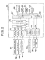
- Fig. 2 is a block diagram illustrating the inside of the ECU 39 and various signals inputted thereto and outputted therefrom.
- the ECU 39 is typically composed of a central processing unit (CPU) 63, a read only memory (ROM) 64, a random access memory (RAM) 65, a back up RAM 66, an input port 67, an output port 68, an inner bus 69, buffers 70, a multiplexer 71, an A/D converter 72, a waveform shaping circuit 73 and driving circuits 74.
- the electric signals outputted from the sensors 57, 58, 59 and 61 are supplied to the A/D converter 72 through the buffers 70 and the multiplexer 71, converted therein into digital signals, and inputted to the input port 67.
- the waveform shaping circuit 73 subjects an electric signal outputted from the sensor 56 to a waveform shaping process, and the electric signal is thereafter inputted to the input port 67.
- the electric signals for driving the step motor 26 and the EVRV 48 are supplied to the driving circuits 74 through the output port 68.
- the electric signals thus supplied to the driving circuits 74 are subjected to a necessary amplification process and outputted to the step motor 26 and the EVRV 48.
- the input port 67 and the output port 68 are connected with the CPU 63, the ROM 64, the RAM 65 and the back up RAM 66 via the inner bus 69.
- a control program stored in the ROM 64 is designed to process parameters that are indicated by electric signals inputted to the ECU 39 and thus performs diesel intake throttle valve control and EGR control.
- Fig. 3a illustrates a flowchart of a program for diesel intake throttle valve control and Fig. 3b is a two-dimensional map used in step 310.
- the program as illustrated in Fig. 3 is carried out, for instance, every 8ms.
- a target number of steps LSTRG that indicates a target opening degree of the diesel intake throttle valve is calculated from an engine revolution NE and a final fuel injection amount QFIN using the two-dimensional map as illustrated in Fig. 3b, which is composed of an axis of abscissa representing the engine revolution NE and an axis of ordinate representing the final fuel injection amount QFIN.
- the two-dimensional map is set such that the target number of steps LSTRG corresponding to a point (NE, QFIN) in a two-dimensional plane ranges, for example, from 0 to 230.
- the target number of steps LSTRG actually assumes a natural number that consecutively changes.
- the unit [mm 3 /st] used in the graph indicates a fuel injection amount per one stroke of a piston.
- the step motor 26 is controlled in accordance with a program executed by the ECU 39 such that the actual number of steps LSACT coincides with the target number of steps LSTRG.
- the target number of steps LSTRG is a natural number which assumes zero when the intake throttle valve 25 is full open and increases as the intake throttle valve 25 is closed.
- Fig. 4 is a flowchart of diesel intake throttle valve control.
- the program as illustrated in Fig. 4 is executed at a predetermined interruption interval.
- step 410 the actual number of steps recognized by the ECU 39 is calculated. If the target number of steps LSTRG is larger than the actual number of steps LSACT, the actual number of steps LSACT is replaced by a value obtained by adding 1 to the current actual number of steps LSACT. If the target number of steps LSTRG is smaller than the actual number of steps LSACT, the actual number of steps LSACT is replaced by a value obtained by subtracting 1 from the current actual number of steps LSACT.
- an interruption time for executing the program as illustrated in Fig. 4 is calculated, for example, as follows. If a source voltage is not lower than 10V, a time TS is replaced by a value obtained by adding 5ms to the time TS. If the source voltage is lower than 10V, the time TS is replaced by a value obtained by adding 10ms to the time TS. Thus, as the source voltage becomes lower, the interval of interruption becomes longer.
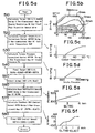
- Fig. 5a is a flowchart of a program for EGR control.
- Figs. 5b through 5f are graphs showing relationships among various parameters used in the steps as illustrated in Fig. 5a.
- the program as illustrated in Fig. 5a is executed, for example, every 8ms.
- a base target EGR valve lift ELBSE which constitutes a criterion of a lift amount of the EGR valve, is calculated from an engine revolution NE and a final fuel injection amount QFIN using a two-dimensional map as illustrated in Fig. 5b, which is composed of an axis of abscissa representing the engine revolution NE and an axis of ordinate representing the final fuel injection amount QFIN.
- the two-dimensional map is set such that the base target EGR valve lift ELBSE corresponding to a point (NE, QFIN) in a two-dimensional plane consecutively ranges, for example, from 0mm to 6mm.
- the engine revolution NE is obtained from an electric signal outputted from the rotational speed sensor 56.
- a coolant temperature correction factor METHW is calculated from a coolant temperature THW using a one-dimensional map as illustrated in Fig. 5c, which is composed of an axis of abscissa representing the coolant temperature THW and an axis of ordinate representing the coolant temperature correction factor METHW.
- the one-dimensional map is set such that the coolant temperature correction factor METHW at a certain coolant temperature THW assumes, for example, a value ranging from 0 to 1.
- the coolant temperature THW is obtained from an electric signal outputted from the coolant temperature sensor 57.
- an intake pressure correction factor MEPIM is calculated from an intake pressure PA using a one-dimensional map as illustrated in Fig. 5d, which is composed of an axis of abscissa representing the intake pressure PA and an axis of ordinate representing the intake pressure correction factor MEPIM.
- the one-dimensional map is set such that the intake pressure correction factor MEPIM at a certain intake pressure PA assumes, for example, a value ranging from 0 to 1.
- the intake pressure PA is obtained from an electric signal outputted from the intake pressure sensor 59.
- step 550 an actual EGR valve lift ELACT corresponding to an actual lift amount of the EGR valve is detected using a sensor for detecting an actual lift amount of the EGR valve (EGR valve lift sensor).
- a base EGR control amount IEBSE is calculated from the final target EGR valve lift ELTRG using a one-dimensional map as illustrated in Fig. 5e, which is composed of an axis of abscissa representing the final target EGR valve lift ELTRG and an axis of ordinate representing the base EGR control amount IEBSE.
- the one-dimensional map is set such that the base EGR control amount IEBSE at a certain final target EGR valve lift ELTRG assumes, for example, a value ranging from about 300mA to about 500mA.
- a feedback EGR control amount IEFB is calculated from (the final target EGR valve lift ELTRG - the actual EGR valve lift ELACT) using a one-dimensional map as illustrated in Fig. 5f, which is composed of an axis of abscissa representing (the final target EGR valve lift ELTRG - the actual EGR valve lift ELACT) and an axis of ordinate representing the feedback EGR control amount IEFB.
- the one-dimensional map is set such that the feedback EGR control amount IEFB at a certain value of (the final target EGR valve lift ELTRG - the actual EGR valve lift ELACT) assumes, for example, a value ranging from about -100mA to about 100mA.
- the ECU 39 performs control such that a current corresponding to the final EGR control amount IEFIN flows through the EVRV 48.
- Fig. 6 is a flowchart of a program used in the intake throttle valve control apparatus for an engine with EGR control according to the present invention.
- the program as illustrated in Fig. 6 is executed, for example, every 8ms. That is, the control operation according to the program starts with the symbol “START” in Fig. 6 and ends with the symbol “RETURN” in Fig. 6. If the control operation proceeds to the symbol "RETURN", the program is not executed until the control operation proceeds to the symbol "START" again.
- steps 601 to 604 the opening degree of the intake throttle valve is corrected when the lift amount of the EGR valve deviates from a target value.
- steps 610 to 614 the lift amount of the EGR valve is corrected when the opening degree of the intake throttle valve deviates from a target value, as it is disclosed in JP-082 101 95.
- steps 621 to 625 the final fuel injection amount QFIN is corrected when the opening degree of the intake throttle valve deviates from a target value.
- the millimeter is a unit of the variables ELACT, ELTRG and ELD.
- step 602 it is determined whether or not the absolute value of the EGR valve lift difference ELD is smaller than 0.5. If YES in step 602, the operation proceeds to step 610. If NO in step 602, the operation proceeds to step 603.
- an intake throttle valve opening degree correction amount LSD is calculated from the EGR valve lift difference ELD. This calculation is carried out based on a look-up table as illustrated in Table 1. ELD -6 -3 0 3 6 LSD 10 5 0 -30 -60
- the number of steps of the step motor for driving the intake throttle valve is a unit of the intake throttle valve opening degree correction amount LSD.
- the intake throttle valve opening degree correction amount LSD is negative.
- the EGR valve lift difference ELD is negative (that is, when the actual EGR valve lift ELACT is smaller than the final target EGR valve lift ELTRG)
- the intake throttle valve opening degree correction amount LSD is positive. In either case, the larger the EGR valve lift difference ELD becomes, the larger the absolute value of the intake throttle valve opening degree correction amount LSD becomes.
- step 604 the target number of steps LSTRG is corrected by adding thereto the intake throttle valve opening degree correction amount LSD.
- the EGR valve lift difference ELD is positive (that is, when the actual EGR valve lift ELACT is larger than the final target EGR valve lift ELTRG)
- the EGR operation is excessively performed.
- the EGR operation is restricted by opening the intake throttle valve.
- the opening degree of the intake throttle valve is increased by adding the intake throttle valve opening degree correction amount LSD of a negative value to the target number of steps LSTRG so as to reduce the target number of steps LSTRG.
- step 610 it is determined whether or not the EGR operation is carried out. If YES in step 610, the operation proceeds to step 611. If NO in step 610, the operation proceeds to step 621. To be more specific, it is determined that the EGR operation is not carried out if the actual EGR valve lift ELACT is equal to zero, that is, if the EGR valve is completely closed.
- Steps 611 to 614 correspond to steps 601 to 604 respectively. While the variable LSD is calculated from the variable ELD in steps 601 to 604, the variable ELD is calculated from the variable LSD in steps 611 to 614. In other words, while the opening degree of the intake throttle valve 25 is corrected in steps 601 to 604 when the lift amount of the EGR valve 42 deviates from a predetermined value, the lift amount of the EGR valve 42 is corrected in steps 611 to 614 when the opening degree of the intake throttle valve 25 deviates from a predetermined value.
- the number of steps of the step motor for driving the intake throttle valve is a unit of the variables LSACT and LSTRG.
- step 612 it is determined whether or not the absolute value of the intake throttle valve opening degree difference LSD is smaller than 20. If YES in step 612, the operation proceeds to step 621. If NO in step 612, the operation proceeds to step 613.
- an EGR valve lift correction amount ELD is calculated from the intake throttle valve opening degree difference LSD. This calculation is carried out based on a look-up table as illustrated in Table 2. LSD -60 -30 0 30 60 ELD 6 3 0 -0.5 -1
- the EGR valve lift correction amount ELD is expressed as a lift amount of the EGR valve in millimeter. Referring to Table 2, when the intake throttle valve opening degree difference LSD is positive (that is, when the actual number of steps LSACT is larger than the target number of steps LSTRG), the EGR valve lift correction amount ELD is negative. On the contrary, when the intake throttle valve opening degree difference LSD is negative (that is, when the actual number of steps LSACT is smaller than the target number of steps LSTRG), the EGR valve lift correction amount ELD is positive. In either case, the larger the absolute value of the intake throttle valve opening degree difference LSD becomes, the larger the absolute value of the EGR valve lift correction amount ELD becomes.
- the final target EGR valve lift ELTRG is corrected by adding thereto the EGR valve lift correction amount ELD.
- ELD EGR valve lift correction amount
- the lift amount of the EGR valve is reduced by adding the EGR valve lift correction amount ELD of a negative value to the final target EGR valve lift ELTRG so as to reduce the final target EGR valve lift ELTRG.
- This control process according to the present invention makes it possible to prevent smoke from being generated and improve a state of combustion as well as drivability.
- step 622 it is determined whether the intake throttle valve opening degree difference LSD is not smaller than 20. If the intake throttle valve opening degree difference LSD is not smaller than 20, the operation proceeds to step 623. If the intake throttle valve opening degree difference LSD is smaller than 20, the operation comes to an end.
- a fuel injection correction amount QD is calculated from the intake throttle valve opening degree difference LSD. This calculation is carried out based on a look-up table as illustrated in Table 3. LSD 0 20 40 60 80 LSD 0 2 4 8 16
- the fuel injection correction amount QD is expressed as a fuel injection amount [mm 3 /st] per one stroke of the piston.
- the intake throttle valve opening degree difference LSD is positive (that is, when the actual number of steps LSACT is larger than the target number of steps LSTRG)
- the fuel injection correction amount QD is positive.
- a maximum fuel injection amount QFULL in a full load state is corrected by subtracting therefrom the fuel injection correction amount QD.
- a maximum fuel injection amount QFULLC corrected by the intake throttle valve opening degree difference LSD during fuel injection control, it is possible to perform cooperative control of the intake throttle valve and fuel injection. For example, when the intake throttle valve opening degree difference LSD is positive (that is, when the actual number of steps LSACT is larger than the target number of steps LSTRG), the intake throttle valve 25 is excessively throttled. Thus, a later-described final fuel injection amount QFI is restricted by reducing the corrected maximum fuel injection amount QFULLC.
- the fuel injection amount is reduced by subtracting the fuel injection correction amount QD from the maximum fuel injection amount QFULL in a full load state so as to reduce the corrected maximum fuel injection amount QFULLC.
- step 625 the smaller of a governor injection amount QGOV and the corrected maximum fuel injection amount QFULLC is determined as the final fuel injection amount QFIN and is used during fuel injection control.
- the governor injection amount QGOV is obtained from the engine revolution NE and a governor pattern that is preliminarily set so as to maintain the engine revolution NE in accordance with an accelerator opening degree (engine load).
- the threshold values 0.5, 20 and 20 used in steps 602, 612 and 622 respectively may be changed depending on the object to be controlled or the control characteristics. It is further to be noted that the look-up tables 1 through 3 are given merely as examples and that the tables may contain additional pairs of values. Further, the correction amount may be obtained by interpolating the values cited in the tables.
- the aforementioned programs used in the intake throttle valve control apparatus for an engine with EGR control are typically stored in the ROM 64 disposed inside the ECU 39, the present invention is not limited to such a construction. Functions of the aforementioned programs may also be implemented by a general purpose processor programmed based on instructions for causing the CPU 63 to carry out predetermined steps, a hardware element containing a wiring logic for carrying out predetermined steps or a general purpose processor programmed and combined with a specific hardware.
Landscapes
- Engineering & Computer Science (AREA)
- Chemical & Material Sciences (AREA)
- Combustion & Propulsion (AREA)
- Mechanical Engineering (AREA)
- General Engineering & Computer Science (AREA)
- Electrical Control Of Air Or Fuel Supplied To Internal-Combustion Engine (AREA)
- Output Control And Ontrol Of Special Type Engine (AREA)
- Combined Controls Of Internal Combustion Engines (AREA)
- Exhaust-Gas Circulating Devices (AREA)
- Control Of Throttle Valves Provided In The Intake System Or In The Exhaust System (AREA)
Claims (6)
- Appareil de commande de papillon des gaz d'admission pour un moteur à combustion interne (11) avec une commande EGR destinée à ajuster une quantité de recirculation des gaz d'échappement à une valeur cible, comprenant une soupape EGR (40) destinée à renvoyer les gaz d'échappement vers le moteur à combustion interne, un papillon des gaz d'admission (25) disposé dans un passage d'admission (16) et un moyen de commande (39) destiné à ajuster les degrés d'ouverture de la soupape EGR et du papillon des gaz d'admission aux valeurs cibles respectives, caractérisé en ce que lorsque la soupape EGR (42) prend un degré d'ouverture réelle différent du degré d'ouverture souhaité d'une valeur prédéterminée ou plus, l'appareil de commande de papillon des gaz d'admission est adapté pour réaliser une commande de correction d'une manière telle que le papillon des gaz d'admission prend un degré d'ouverture différent d'un degré d'ouverture souhaité correspondant à un état de fonctionnement du moteur à combustion interne (11), dans lequel
le papillon des gaz d'admission (25) est adapté pour prendre un degré d'ouverture dont la quantité de correction est augmentée proportionnellement à une différence entre un degré d'ouverture réel de la soupape EGR (42) et un degré d'ouverture souhaité de la soupape EGR (42). - Appareil de commande de papillon des gaz d'admission selon la revendication 1, caractérisé en ce que l'appareil de commande de papillon des gaz d'admission est adapté pour réaliser une correction de façon à augmenter un degré d'ouverture du papillon des gaz d'admission (25) lorsque la soupape EGR (42) prend un degré d'ouverture réel supérieur au degré d'ouverture souhaité.
- Appareil de commande dé papillon des gaz d'admission selon la revendication 1, caractérisé en ce que l'appareil de commande de papillon des gaz d'admission est adapté pour déterminer une quantité d'injection de carburant dans un état de pleine charge en se basant sur une différence entre un degré d'ouverture réel du papillon des gaz d'admission (25) et un degré d'ouverture souhaité du papillon des gaz d'admission (25).
- Appareil de commande de papillon des gaz d'admission selon la revendication 3, caractérisé en ce que l'appareil de commande de papillon des gaz d'admission est adapté pour réaliser une correction de façon à réduire une quantité d'injection de carburant lorsque le papillon des gaz d'admission (25) prend un degré d'ouverture réel inférieur à un degré d'ouverture souhaité.
- Appareil de commande de papillon des gaz d'admission selon l'une quelconque des revendications précédentes, caractérisé en ce que la soupape EGR (42) est un clapet à disque fonctionnant sur pression négative et pression atmosphérique de façon à ouvrir et fermer un passage EGR (41).
- Appareil de commande de papillon des gaz d'admission selon les revendications précédentes, caractérisé en ce qu'une soupape de régulation de vide électrique (48) est prévue pour ajuster une pression négative et une pression atmosphérique appliquée à la soupape EGR (42).
Applications Claiming Priority (3)
| Application Number | Priority Date | Filing Date | Title |
|---|---|---|---|
| JP09170562A JP3092547B2 (ja) | 1997-06-26 | 1997-06-26 | Egr制御付きエンジンの吸気絞り弁制御装置 |
| JP17056297 | 1997-06-26 | ||
| JP170562/97 | 1997-06-26 |
Publications (3)
| Publication Number | Publication Date |
|---|---|
| EP0887532A2 EP0887532A2 (fr) | 1998-12-30 |
| EP0887532A3 EP0887532A3 (fr) | 2000-05-10 |
| EP0887532B1 true EP0887532B1 (fr) | 2005-08-17 |
Family
ID=15907156
Family Applications (1)
| Application Number | Title | Priority Date | Filing Date |
|---|---|---|---|
| EP98111865A Expired - Lifetime EP0887532B1 (fr) | 1997-06-26 | 1998-06-26 | Dispositif de commande pour papillon d'admission d'air de moteur à combustion interne |
Country Status (4)
| Country | Link |
|---|---|
| EP (1) | EP0887532B1 (fr) |
| JP (1) | JP3092547B2 (fr) |
| DE (1) | DE69831194T2 (fr) |
| ES (1) | ES2245012T3 (fr) |
Cited By (1)
| Publication number | Priority date | Publication date | Assignee | Title |
|---|---|---|---|---|
| CN103354865A (zh) * | 2011-02-01 | 2013-10-16 | 丰田自动车株式会社 | 内燃机的控制装置 |
Families Citing this family (7)
| Publication number | Priority date | Publication date | Assignee | Title |
|---|---|---|---|---|
| JP2000303914A (ja) * | 1999-04-23 | 2000-10-31 | Mazda Motor Corp | エンジンの排気ガス還流装置 |
| JP3885569B2 (ja) * | 2001-11-29 | 2007-02-21 | いすゞ自動車株式会社 | 内燃機関のegr制御装置 |
| JP2007270642A (ja) * | 2006-03-30 | 2007-10-18 | Mitsubishi Fuso Truck & Bus Corp | 内燃機関のegr制御装置 |
| JP2008215112A (ja) | 2007-02-28 | 2008-09-18 | Mitsubishi Heavy Ind Ltd | ディーゼルエンジンシステム及びその制御方法 |
| KR101316308B1 (ko) * | 2012-01-26 | 2013-10-10 | 현대자동차주식회사 | 디젤 차량의 배기가스 저감방법 |
| US10570836B2 (en) * | 2017-06-14 | 2020-02-25 | Aisan Kogyo Kabushiki Kaisha | EGR control apparatus for engine with supercharger and control method of EGR device for engine with supercharger |
| CN109838315B (zh) * | 2017-11-29 | 2021-09-10 | 长城汽车股份有限公司 | 开度调节方法、开度调节装置及车辆 |
Family Cites Families (5)
| Publication number | Priority date | Publication date | Assignee | Title |
|---|---|---|---|---|
| JPS59105955A (ja) * | 1982-12-08 | 1984-06-19 | Mazda Motor Corp | デイ−ゼルエンジンの排気還流装置 |
| DE4037913A1 (de) * | 1990-08-28 | 1992-06-04 | Bayerische Motoren Werke Ag | Steuerverfahren fuer ein abgasrueckfuehr-steuerorgan |
| JPH0544507A (ja) | 1991-08-20 | 1993-02-23 | Nissan Motor Co Ltd | デイーゼルエンジンの排気還流装置 |
| JP2869916B2 (ja) * | 1993-11-01 | 1999-03-10 | 本田技研工業株式会社 | 内燃機関の燃料制御装置 |
| JPH08210195A (ja) * | 1995-02-06 | 1996-08-20 | Nissan Motor Co Ltd | ディーゼル機関の排気還流制御装置 |
-
1997
- 1997-06-26 JP JP09170562A patent/JP3092547B2/ja not_active Expired - Fee Related
-
1998
- 1998-06-26 DE DE69831194T patent/DE69831194T2/de not_active Expired - Fee Related
- 1998-06-26 ES ES98111865T patent/ES2245012T3/es not_active Expired - Lifetime
- 1998-06-26 EP EP98111865A patent/EP0887532B1/fr not_active Expired - Lifetime
Cited By (2)
| Publication number | Priority date | Publication date | Assignee | Title |
|---|---|---|---|---|
| CN103354865A (zh) * | 2011-02-01 | 2013-10-16 | 丰田自动车株式会社 | 内燃机的控制装置 |
| CN103354865B (zh) * | 2011-02-01 | 2015-06-17 | 丰田自动车株式会社 | 内燃机的控制装置 |
Also Published As
| Publication number | Publication date |
|---|---|
| DE69831194D1 (de) | 2005-09-22 |
| JPH1113511A (ja) | 1999-01-19 |
| ES2245012T3 (es) | 2005-12-16 |
| JP3092547B2 (ja) | 2000-09-25 |
| EP0887532A2 (fr) | 1998-12-30 |
| DE69831194T2 (de) | 2006-06-08 |
| EP0887532A3 (fr) | 2000-05-10 |
Similar Documents
| Publication | Publication Date | Title |
|---|---|---|
| US5738126A (en) | Apparatus for controlling a diesel engine with exhaust | |
| US4402289A (en) | Idle speed control method and system for an internal combustion engine | |
| US6016788A (en) | Fuel injection control system for a diesel engine | |
| US4649878A (en) | Method of feedback-controlling idling speed of internal combustion engine | |
| JPS585447A (ja) | 車輛駆動用内燃機関 | |
| EP0887532B1 (fr) | Dispositif de commande pour papillon d'admission d'air de moteur à combustion interne | |
| JPH08338277A (ja) | 内燃機関の回転数制御装置 | |
| US4757683A (en) | Exhaust gas recirculation method for internal combustion engines | |
| US6220232B1 (en) | Load control in an internal combustion engine | |
| JP2583361B2 (ja) | 過給機付ディーゼルエンジンの排気還流装置 | |
| JPH0692757B2 (ja) | 内燃機関のバイパス空気量制御方法 | |
| US4493300A (en) | Method of controlling the fuel supply to an internal combustion engine at deceleration | |
| JP3838303B2 (ja) | 排気再循環制御装置 | |
| JP3478092B2 (ja) | アイドル吸気圧学習機能を有するエンジン制御装置 | |
| JP3163696B2 (ja) | ディーゼル機関の排気ガス還流制御装置 | |
| JPS6241951A (ja) | エンジンのアイドル回転数制御装置 | |
| JPH0245631A (ja) | 内燃エンジンの燃料供給制御装置 | |
| JP3859809B2 (ja) | 内燃機関の吸入空気量制御装置 | |
| JPS6397862A (ja) | デイ−ゼルエンジンの排気ガス再循環制御方法 | |
| JP4273950B2 (ja) | 内燃機関の吸気制御装置 | |
| JP3209147B2 (ja) | ディーゼルエンジンのステップモータ式吸気絞り弁制御装置 | |
| JP3632446B2 (ja) | 内燃機関のegr制御装置 | |
| JPH08296470A (ja) | ディーゼル機関の制御装置 | |
| JPH06101525A (ja) | ディーゼルエンジンの燃料噴射量制御装置 | |
| JPH11200924A (ja) | 内燃機関の燃料噴射量制御装置 |
Legal Events
| Date | Code | Title | Description |
|---|---|---|---|
| PUAI | Public reference made under article 153(3) epc to a published international application that has entered the european phase |
Free format text: ORIGINAL CODE: 0009012 |
|
| 17P | Request for examination filed |
Effective date: 19980710 |
|
| AK | Designated contracting states |
Kind code of ref document: A2 Designated state(s): BE DE ES FR GB IT |
|
| AX | Request for extension of the european patent |
Free format text: AL;LT;LV;MK;RO;SI |
|
| PUAL | Search report despatched |
Free format text: ORIGINAL CODE: 0009013 |
|
| AK | Designated contracting states |
Kind code of ref document: A3 Designated state(s): AT BE CH CY DE DK ES FI FR GB GR IE IT LI LU MC NL PT SE |
|
| AX | Request for extension of the european patent |
Free format text: AL;LT;LV;MK;RO;SI |
|
| AKX | Designation fees paid |
Free format text: BE DE ES FR GB IT |
|
| 17Q | First examination report despatched |
Effective date: 20030115 |
|
| GRAP | Despatch of communication of intention to grant a patent |
Free format text: ORIGINAL CODE: EPIDOSNIGR1 |
|
| GRAS | Grant fee paid |
Free format text: ORIGINAL CODE: EPIDOSNIGR3 |
|
| GRAA | (expected) grant |
Free format text: ORIGINAL CODE: 0009210 |
|
| RAP1 | Party data changed (applicant data changed or rights of an application transferred) |
Owner name: TOYOTA JIDOSHA KABUSHIKI KAISHA |
|
| AK | Designated contracting states |
Kind code of ref document: B1 Designated state(s): BE DE ES FR GB IT |
|
| REG | Reference to a national code |
Ref country code: GB Ref legal event code: FG4D |
|
| REF | Corresponds to: |
Ref document number: 69831194 Country of ref document: DE Date of ref document: 20050922 Kind code of ref document: P |
|
| REG | Reference to a national code |
Ref country code: ES Ref legal event code: FG2A Ref document number: 2245012 Country of ref document: ES Kind code of ref document: T3 |
|
| ET | Fr: translation filed | ||
| PLBE | No opposition filed within time limit |
Free format text: ORIGINAL CODE: 0009261 |
|
| STAA | Information on the status of an ep patent application or granted ep patent |
Free format text: STATUS: NO OPPOSITION FILED WITHIN TIME LIMIT |
|
| 26N | No opposition filed |
Effective date: 20060518 |
|
| PGFP | Annual fee paid to national office [announced via postgrant information from national office to epo] |
Ref country code: IT Payment date: 20080626 Year of fee payment: 11 |
|
| PGFP | Annual fee paid to national office [announced via postgrant information from national office to epo] |
Ref country code: ES Payment date: 20080708 Year of fee payment: 11 Ref country code: DE Payment date: 20080703 Year of fee payment: 11 |
|
| PGFP | Annual fee paid to national office [announced via postgrant information from national office to epo] |
Ref country code: FR Payment date: 20080617 Year of fee payment: 11 |
|
| PGFP | Annual fee paid to national office [announced via postgrant information from national office to epo] |
Ref country code: GB Payment date: 20080702 Year of fee payment: 11 |
|
| PGFP | Annual fee paid to national office [announced via postgrant information from national office to epo] |
Ref country code: BE Payment date: 20080813 Year of fee payment: 11 |
|
| BERE | Be: lapsed |
Owner name: *TOYOTA JIDOSHA K.K. Effective date: 20090630 |
|
| GBPC | Gb: european patent ceased through non-payment of renewal fee |
Effective date: 20090626 |
|
| REG | Reference to a national code |
Ref country code: FR Ref legal event code: ST Effective date: 20100226 |
|
| PG25 | Lapsed in a contracting state [announced via postgrant information from national office to epo] |
Ref country code: FR Free format text: LAPSE BECAUSE OF NON-PAYMENT OF DUE FEES Effective date: 20090630 |
|
| PG25 | Lapsed in a contracting state [announced via postgrant information from national office to epo] |
Ref country code: GB Free format text: LAPSE BECAUSE OF NON-PAYMENT OF DUE FEES Effective date: 20090626 |
|
| PG25 | Lapsed in a contracting state [announced via postgrant information from national office to epo] |
Ref country code: DE Free format text: LAPSE BECAUSE OF NON-PAYMENT OF DUE FEES Effective date: 20100101 Ref country code: BE Free format text: LAPSE BECAUSE OF NON-PAYMENT OF DUE FEES Effective date: 20090630 |
|
| REG | Reference to a national code |
Ref country code: ES Ref legal event code: FD2A Effective date: 20090627 |
|
| PG25 | Lapsed in a contracting state [announced via postgrant information from national office to epo] |
Ref country code: ES Free format text: LAPSE BECAUSE OF NON-PAYMENT OF DUE FEES Effective date: 20090627 |
|
| PG25 | Lapsed in a contracting state [announced via postgrant information from national office to epo] |
Ref country code: IT Free format text: LAPSE BECAUSE OF NON-PAYMENT OF DUE FEES Effective date: 20090626 |