EP0890795A2 - Axial gestufte Brennkammer mit schneller Abkühlung der Verbrennungsgase - Google Patents
Axial gestufte Brennkammer mit schneller Abkühlung der Verbrennungsgase Download PDFInfo
- Publication number
- EP0890795A2 EP0890795A2 EP98303598A EP98303598A EP0890795A2 EP 0890795 A2 EP0890795 A2 EP 0890795A2 EP 98303598 A EP98303598 A EP 98303598A EP 98303598 A EP98303598 A EP 98303598A EP 0890795 A2 EP0890795 A2 EP 0890795A2
- Authority
- EP
- European Patent Office
- Prior art keywords
- quench
- section
- holes
- region
- combustor
- Prior art date
- Legal status (The legal status is an assumption and is not a legal conclusion. Google has not performed a legal analysis and makes no representation as to the accuracy of the status listed.)
- Withdrawn
Links
- 238000010791 quenching Methods 0.000 title claims abstract description 238
- 238000002485 combustion reaction Methods 0.000 claims abstract description 61
- 230000035515 penetration Effects 0.000 claims abstract description 32
- 238000001816 cooling Methods 0.000 claims abstract description 27
- 238000011144 upstream manufacturing Methods 0.000 claims abstract description 11
- 239000000446 fuel Substances 0.000 claims description 25
- 239000007789 gas Substances 0.000 claims description 18
- 238000000034 method Methods 0.000 claims description 13
- 230000003134 recirculating effect Effects 0.000 claims description 2
- 238000004513 sizing Methods 0.000 claims 1
- UGFAIRIUMAVXCW-UHFFFAOYSA-N Carbon monoxide Chemical compound [O+]#[C-] UGFAIRIUMAVXCW-UHFFFAOYSA-N 0.000 description 6
- 229910002091 carbon monoxide Inorganic materials 0.000 description 6
- 238000009792 diffusion process Methods 0.000 description 6
- IJGRMHOSHXDMSA-UHFFFAOYSA-N Atomic nitrogen Chemical compound N#N IJGRMHOSHXDMSA-UHFFFAOYSA-N 0.000 description 5
- 239000000203 mixture Substances 0.000 description 5
- 238000006243 chemical reaction Methods 0.000 description 3
- 238000010438 heat treatment Methods 0.000 description 3
- 230000000149 penetrating effect Effects 0.000 description 3
- XLYOFNOQVPJJNP-UHFFFAOYSA-N water Substances O XLYOFNOQVPJJNP-UHFFFAOYSA-N 0.000 description 3
- 238000010793 Steam injection (oil industry) Methods 0.000 description 2
- 239000000567 combustion gas Substances 0.000 description 2
- 238000009826 distribution Methods 0.000 description 2
- 230000000694 effects Effects 0.000 description 2
- 239000003344 environmental pollutant Substances 0.000 description 2
- 229910052757 nitrogen Inorganic materials 0.000 description 2
- 231100000719 pollutant Toxicity 0.000 description 2
- 230000000171 quenching effect Effects 0.000 description 2
- QVGXLLKOCUKJST-UHFFFAOYSA-N atomic oxygen Chemical compound [O] QVGXLLKOCUKJST-UHFFFAOYSA-N 0.000 description 1
- 230000004888 barrier function Effects 0.000 description 1
- 238000004891 communication Methods 0.000 description 1
- 230000007613 environmental effect Effects 0.000 description 1
- 239000002737 fuel gas Substances 0.000 description 1
- 239000001301 oxygen Substances 0.000 description 1
- 229910052760 oxygen Inorganic materials 0.000 description 1
- 230000001105 regulatory effect Effects 0.000 description 1
- 238000000926 separation method Methods 0.000 description 1
- 230000007704 transition Effects 0.000 description 1
- 238000009827 uniform distribution Methods 0.000 description 1
Images


Classifications
-
- F—MECHANICAL ENGINEERING; LIGHTING; HEATING; WEAPONS; BLASTING
- F23—COMBUSTION APPARATUS; COMBUSTION PROCESSES
- F23R—GENERATING COMBUSTION PRODUCTS OF HIGH PRESSURE OR HIGH VELOCITY, e.g. GAS-TURBINE COMBUSTION CHAMBERS
- F23R3/00—Continuous combustion chambers using liquid or gaseous fuel
- F23R3/02—Continuous combustion chambers using liquid or gaseous fuel characterised by the air-flow or gas-flow configuration
- F23R3/04—Air inlet arrangements
- F23R3/06—Arrangement of apertures along the flame tube
-
- F—MECHANICAL ENGINEERING; LIGHTING; HEATING; WEAPONS; BLASTING
- F23—COMBUSTION APPARATUS; COMBUSTION PROCESSES
- F23R—GENERATING COMBUSTION PRODUCTS OF HIGH PRESSURE OR HIGH VELOCITY, e.g. GAS-TURBINE COMBUSTION CHAMBERS
- F23R3/00—Continuous combustion chambers using liquid or gaseous fuel
- F23R3/28—Continuous combustion chambers using liquid or gaseous fuel characterised by the fuel supply
- F23R3/34—Feeding into different combustion zones
Definitions
- This application relates to turbine combustion, and in particular relates to a rich-quench-lean turbine combustor with low NOx and CO emissions.
- a rich-quench-lean (RQL) gas turbine combustor Another method to reduce NOx emissions is by utilizing a rich-quench-lean (RQL) gas turbine combustor.
- a rich-quench-lean combustor a combustor is divided into a fuel rich stage, a quench stage and a fuel lean stage.
- a fuel rich stage (rich meaning an equivalence ratio ⁇ > 1), a fuel-air mixture is partially burned because the fuel-air mixture is introduced with an insufficient amount of air to complete combustion.
- Fuel rich combustion is desirable because a large portion of any bound nitrogen species (for example, NH 3 ) in the fuel will be converted into N 2 during combustion within the rich stage. By converting the reactive bound nitrogen species to relatively nonreactive N 2 , emissions of NOx are reduced.
- quench air additional air, termed in the art to be “quench air”
- quench air is added downstream from the rich stage to complete combustion within a lean stage. If the quench air is not uniformly and rapidly introduced, however, high NOx levels will be produced in local regions of the combustor due to high temperatures. Although rapid mixing can be achieved with a high pressure drop, this reduces the overall efficiency of the turbine.
- a combustor cooperating with a compressor in driving a gas turbine includes a cylindrical outer combustor casing.
- a combustion liner having an upstream rich section, a quench section and a downstream lean section, is disposed within the outer combustor casing defining a combustion chamber having at least a core quench region and an outer quench region.
- a first plurality of quench holes are disposed within the liner at the quench section having a first diameter to provide cooling jet penetration to the core region of the quench section of the combustion chamber.
- a second plurality of quench holes are disposed within the liner at the quench section having a second diameter to provide cooling jet penetration to the outer region of the quench section of the combustion chamber.
- the combustion chamber quench section further includes at least one middle region and at least a third plurality of quench holes disposed within the liner at the quench section having a third diameter to provide cooling jet penetration to at least one middle region of the quench section of the combustion chamber.
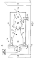
- An industrial turbine engine 10 includes a compressor 12 disposed in serial flow communication with a rich-quench-lean combustor 14 and a single or multi-stage turbine 16, as shown in FIG. 1.
- Turbine 16 is coupled to compressor 12 by a drive shaft 18, a portion of which drive shaft 18 extends for powering an electrical generator (not shown) for generating electrical power.
- compressor 12 discharges compressed air 20 into combustor 14 wherein compressed air 20 is mixed with fuel 19, as discussed below, and ignited for generating combustion gases 24 from which energy is extracted by turbine 16 for rotating shaft 18 to power compressor 12, as well as producing output power for driving the generator or other external load.
- Compressed air 20 is divided into rich stage air 21, lean stage air 22, and quench air 23 through appropriate apportionment of the open areas throughout a combustion liner 32.
- combustor 14 comprises a cylindrical outer combustor casing 26 which has at least one air inlet 28 for supplying air to combustor 14.
- Circumferentially disposed within outer combustor casing 26 are a plurality of circumferentially adjoining combustion chambers 30, each defined by tubular combustion liner 32.
- Each combustion chamber 30 further includes a generally flat dome 34 at an upstream end 36 and an outlet 38 at a downstream end 40.
- a transition piece 42 joins the several can outlets 38 to effect a common discharge of combustion gases 24 through an exhaust 44 to turbine 16.
- combustor 14 includes a rich section 46 at upstream end 36, a quench section 48 and a downstream lean section 50.
- Rich section 46 consists of a generally cylindrical section 52 followed by a conical section 54, which conical section 54 reduces the diameter of the flow path.
- Conical section 54 is necessary to prevent a low pressure core of the recirculating flow from drawing lean section 50 gases upstream into rich section 46.
- Conical section 54 also provides a convenient method of reducing the flow area to a reasonable size for quenching.
- Quench section 48 consists of a cylindrical section 56 and a backward facing step 58 at the entrance to lean section 50.
- Backward facing step 58 enhances the combustion stability and mixing in lean section 50 by creating a recirculation zone at the entrance to lean section 50.
- a fuel nozzle 60 is located ahead of rich stage 46 to introduce fuel 19 and rich stage air 21 within combustor 14 so as to produce a swirl stabilized rich stage diffusion flame
- Several examples of methods of introducing the fuel and air into the combustor with a fuel nozzle are described in "Design and Performance of Low Heating Value Fuel Gas Turbine Combustors," by R. A. Battista, A. S. Feitelberg, and M. A. Lacey, American Society of Mechanical Engineers, Paper No. 96-GT-531.
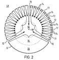
- quench section 48 is divided, for purposes of calculating quench air needs as discussed below, into three separate regions, a core region 62, a middle region 64, and an outer region 66, as shown in FIG. 2.
- region for example outer region 66, as used in reference to quench section 48 does not refer to physical separations or barriers or the like dividing quench section 48. Instead, the term region, as used in reference to quench section 48 refers to apportionment of quench section for purposes of calculating quench air needs.
- core region 62 occupies the space between centerpoint 68 and one third of the radial distance between centerpoint 68 and combustion liner 32.
- Middle region occupies the space between one third of the radial distance and two thirds of the radial distance from centerpoint 68 and combustion liner 32, and outer region 66 occupies the space between two thirds of the radial distance and combustion liner 32.
- core region 62 is essentially circular in cross section, while middle region 64 and outer region 66 are essentially annular in cross section, as shown in FIG. 2.
- core region 62 occupies one third of the cross-sectional area of quench section 48
- middle region 64 occupies one third of the cross-sectional area of quench section 48
- outer region 66 occupies one third of the cross-sectional area of quench section 48.
- the fraction of the total quench air apportioned to any region is equal to the fraction of the cross-sectional area occupied by that region.
- a first plurality of quench holes 70 are circumferentially distributed about combustion liner 32 at quench section 48, as shown in FIG. 2.
- First plurality of quench holes 70 are sized so as to provide cooling jet penetration to core region 62 of quench section 48. Larger quench holes create larger jets having greater momentum, enabling greater penetration into a hot gas flow.
- a second plurality of quench holes 72 are circumferentially distributed about combustion liner 32 at quench section 48.
- Second plurality of quench holes 72 are sized so as to provide cooling jet penetration to middle region 64 of quench section 48.
- a third plurality of quench holes 74 are circumferentially distributed about combustion liner 32 at quench section 48.
- Third plurality of quench holes 74 are sized so as to provide cooling jet penetration to outer region 66 of quench section 48. Accordingly, a rapid mixing quench is accomplished by forcing relatively uniform distribution of the quench air into the radially stratified core region 62, middle region 64 and outer region 66.
- Each set of quench holes is sized using standard correlations for jets penetrating into a cross flow, as discussed below. Since a significant portion of combustion liner 32 is removed for the quench holes about quench section 48, a double thickness liner 32 may be utilized at quench section 48 to maintain overall structural integrity of combustion liner 32.
- first plurality of quench holes 70 comprise between about two to about ten quench holes with a diameter in the range between about 0.1 in. to about 0.3 in.
- First plurality of quench holes 70 are spaced about the periphery of quench section 48, each angularly spaced in the range between about 30° to about 180° apart from one another.
- Second plurality of quench holes 72 comprise between about twenty to about sixty quench holes with a diameter in the range between about 0.05 in. to about 0.2 in.
- Second plurality of quench holes 72 are spaced about the periphery of quench section 48, each angularly spaced in the range between about 5° to about 20° apart from one another.
- second plurality of quench holes 72 are axially offset from first plurality of quench holes 70 in the range between about 0.05 in. to about 0.3 in.
- offset refers to respective quench holes disposed such that one set of quench holes is located closer to upstream rich section and the other set of quench holes is located closer to downstream lean section.
- Third plurality of quench holes 74 comprise between about one hundred to about five hundred quench holes with a diameter in the range between about 0.005 in. to about 0.1 in. Third plurality of quench holes 74 are spaced about the periphery of quench section 48, each angularly spaced in the range between about 0.5° to about 7° apart from one another.
- third plurality of quench holes 74 comprise two spaced bands of quench holes 74 axially offset by a distance between about 0.05 in. to about 0.1 in. In one embodiment, third plurality of quench holes 74 are axially offset from first plurality of quench holes 70 in the range between about 0.1 in. to about 0.3 in and from second plurality of quench holes 72 in the range between about 0.05 in. to about 0.2 in.
- each region 72, 74, 76 receives an amount of quench air which is proportional to a region's respective cross-sectional area.
- core region 62 receives about 11% of the quench air
- middle region 64 and outer region 66 receive about 32% and about 56% of the quench air, respectively.
- core region 62, middle region 64 and outer region 66 each receive about 33% of the available quench air.
- quench section 48 is divided into two separate regions, a core region 162, and an outer region 164, as shown in FIG. 3.
- core region 162 occupies the space between a centerpoint 68 and one half of the radial distance between centerpoint 68 and combustion liner 32 and outer region 164 occupies the space between one half of the radial distance, measured from centerpoint 68, and the combustion liner 32.
- inner region 62 is circular in cross section while outer region 66 is annular in cross section, as shown in FIG. 3.
- inner region 162 occupies one half of the cross-sectional area of quench section 48 and outer region 164 occupies one half of the cross-sectional area of quench section 48.
- a first plurality of quench holes 170 are disposed within combustion liner 32 at quench section 48, as shown in FIG. 3.
- First plurality of quench holes 170 are sized so as to provide cooling jet penetration to inner region 162 of quench section 48.
- a second plurality of quench holes 172 are disposed within combustion liner 32 at quench section 48.
- Second plurality of quench holes 172 are sized so as to provide cooling jet penetration to outer region 164 of quench section 48.
- Each set of quench holes is sized using standard correlations for jets penetrating into a cross flow.
- first plurality of quench holes 170 comprise between about two to about ten quench holes with a diameter in the range between about 0.1in. to about 2.0 in.
- First plurality of quench holes 170 are spaced about the periphery of quench section 48, each angularly spaced in the range between about 30° to about 180° apart from one another.
- Second plurality of quench holes 172 comprise between about twenty to about sixty quench holes with a diameter in the range between about 0.05 in. to about 0.3 in.
- Second plurality of quench holes 172 are spaced about the periphery of quench section 48, each angularly spaced in the range between about 5° to about 20° apart from one another.
- second plurality of quench holes 172 are axially offset from first plurality of quench holes 170 in the range between about 0.05 in. to about 0.3 in.
- each region 162, 164 receives an amount of quench air which is proportional to a region's respective cross-sectional area. Such an arrangement allows the distribution of quench air to be proportional to the area of the respective regions. In one embodiment having regions of equal area, inner region 162, and outer region 164 each receive about 50% of the available quench air.
- quench section 48 is divided into four separate regions, a core region 260, a first middle region 262, a second middle region 264 and an outer region 266, as shown in FIG. 4.
- core region 260 occupies the space between a centerpoint 68 and one fourth of the radial distance between centerpoint 68 and combustion liner 32
- first middle region 262 occupies the space between one four of the radial distance between centerpoint 68 and combustion liner 32 and one half of the radial distance between centerpoint 68 and combustion liner 32
- second middle region 264 occupies the space between one half of the radial distance between centerpoint 68 and combustion liner 32 and three fourths of the radial distance
- outer region 266 occupies the space between three fourths of the radial distance between centerpoint 68 and combustion liner 32.
- core region 260, first middle region 262, second middle region 264 and outer region 266 each occupy one fourth of the cross-sectional area of quench section 48.
- a first plurality of quench holes 270 are disposed within combustion liner 32 at quench section 48, as shown in FIG. 4.
- First plurality of quench holes 270 are sized so as to provide cooling jet penetration to core region 260 of quench section 48.
- a second plurality of quench holes 272 are disposed within combustion liner 32 at quench section 48.
- Second plurality of quench holes 272 are sized so as to provide cooling jet penetration to first middle region 262 of quench section 48.
- a third plurality of quench holes 274 are disposed within combustion liner 32 at quench section 48.
- Third plurality of quench holes 274 are sized so as to provide cooling jet penetration to second middle region 264.
- a fourth plurality of quench holes 276 are disposed within combustion liner 32 at quench section 48. Fourth plurality of quench holes 276 are sized so as to provide cooling jet penetration to outer region 266. Each set of quench holes is sized using standard correlations for jets penetrating into a cross flow.
- the total open area of a respective combustor liner is determined from the desired total air and fuel flow rates, operating pressure, compressor discharge air temperature and desired total pressure drop.
- a typical can-annular gas turbine combustor may have a nominal total open area, for example, of 30 in 2 , a nominal air mass flow rate of, for example, 20lb/s, operate at a nominal pressure of 8 atm, a nominal compressor discharge temperature of 620° and have a nominal total pressure drop of 2.5%. These values are for illustrative purposes only and do not limit the instant invention to a particular size or class of turbine.
- the rich stage open area is typically chosen to allow only enough air into the rich stage to create an equivalence ratio of between about 1.1 to about 1.8.
- the quench stage open area is typically chosen to allow enough air into the combustor to generate a fuel-lean mixture at a temperature between about 2000 F (1095 C) to about 2750 F (1510 C).
- the lean stage open area is apportioned to allow enough air into the combustor to lower the burned gas temperature to the desired turbine inlet temperature range.
- the designer(s) selects either the "equal radii" or “equal area” embodiment, and chooses to the divide the quench section into two regions (a core region and an outer region), three regions (a core region, a middle region and an outer region), or more regions.
- the quench holes are sized so that the maximum radial jet penetration distance, Y max , will penetrate to about the center of a respective region (i.e., core region, middle region, outer region, etc.)
- Y max d hole 1.15 ⁇ j ⁇ j 2 ⁇ b ⁇ b 2 ;
- ⁇ j the density of quench air jet;
- ⁇ b the mass density of the burned gas in the quench section;
- ⁇ j the velocity of the quench air jet;
- the required number of holes of each diameter is then readily determined from the fractional apportionment of the quench air to the respective quench regions.
- the total combustor liner open area must be 30 in 2 to achieve the desired pressure drop.
- the designer further chooses a quench stage diameter of 8 inches, and also chooses to divide the quench section into two region of equal area.
- the core region will have radius of 2.83"
- the outer region will extend 1.17" inward from the combustor wall
- the quench stage will have two sets of holes.
- the large holes will create jets with a maximum penetration depth Y max of 2.59 inches
- the small holes will create jets with a maximum penetration depth Y max of 0.59 inches.
- the designer next calculates the dimensionless ratio Y max /d hole , using the known mass density of the quench air and the burned gas in the quench section, as well as the velocity of the quench air jet and the burned gas flowing through the quench section.
- the combustor operating pressure is 147 psia.
- the quench air jet velocity is calculated in a similar fashion.
- the last step is to calculate the number of holes of each type.
- FIG. 5 shows measured NOx emissions with an air split of 40% rich / 60% lean. With the 40/60 air split, the minimum in NOx emissions occurred at a combustor exit temperature of about 2400 F. The minimum NOx occurred at a rich stage equivalence ratio of about ⁇ rich A 1.25. At the optimum rich stage equivalence ratio, NOx emissions were about 50 ppmv (on a dry, 15% O 2 basis. With approximately 4600 parts per million (ppmv) NH 3 in the fuel, this corresponds to a conversion of NH 3 to NOx of about 5%.
- ppmv parts per million
- NOx emissions were more than a factor of three lower than a conventional diffusion flame combustor burning the same or similar fuel (See Fuel Composition Table above).
- the conversion of NH 3 to NOx ranged from about 20% to about 80%, depending upon the combustor exit temperature.
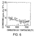
- the measured CO emissions for the model rich-quench-lean combustor 14 discussed above were between about 5 and about 30 ppmv (dry, 15% O 2 ) under all conditions, indicating the quench stage design provided adequate mixing, and the short lean stage provided sufficient residence time to complete combustion.
- the instant invention discloses a rich-quench-lean combustor design that achieves rapid mixing of quench air and rich stage burned gas while maintaining extremely low emission levels and low pressure drop across the quench stage.
Landscapes
- Engineering & Computer Science (AREA)
- Chemical & Material Sciences (AREA)
- Combustion & Propulsion (AREA)
- Mechanical Engineering (AREA)
- General Engineering & Computer Science (AREA)
- Turbine Rotor Nozzle Sealing (AREA)
Applications Claiming Priority (2)
| Application Number | Priority Date | Filing Date | Title |
|---|---|---|---|
| US08/888,252 US5996351A (en) | 1997-07-07 | 1997-07-07 | Rapid-quench axially staged combustor |
| US888252 | 1997-07-07 |
Publications (2)
| Publication Number | Publication Date |
|---|---|
| EP0890795A2 true EP0890795A2 (de) | 1999-01-13 |
| EP0890795A3 EP0890795A3 (de) | 2000-03-22 |
Family
ID=25392856
Family Applications (1)
| Application Number | Title | Priority Date | Filing Date |
|---|---|---|---|
| EP98303598A Withdrawn EP0890795A3 (de) | 1997-07-07 | 1998-05-07 | Axial gestufte Brennkammer mit schneller Abkühlung der Verbrennungsgase |
Country Status (3)
| Country | Link |
|---|---|
| US (1) | US5996351A (de) |
| EP (1) | EP0890795A3 (de) |
| JP (1) | JPH1151394A (de) |
Cited By (1)
| Publication number | Priority date | Publication date | Assignee | Title |
|---|---|---|---|---|
| US5280515A (en) * | 1990-07-10 | 1994-01-18 | Fujitsu Limited | Fault processing system for processing faults of producing points |
Families Citing this family (29)
| Publication number | Priority date | Publication date | Assignee | Title |
|---|---|---|---|---|
| US20020027138A1 (en) * | 1999-02-01 | 2002-03-07 | Yukihiro Hyobu | Magnetic secured container closure with release by movement of magnetic member |
| CN1502007A (zh) | 2000-05-01 | 2004-06-02 | 艾略特能源系统股份有限公司 | 用于能源系统的环形燃烧室 |
| US6708496B2 (en) | 2002-05-22 | 2004-03-23 | Siemens Westinghouse Power Corporation | Humidity compensation for combustion control in a gas turbine engine |
| US6715295B2 (en) | 2002-05-22 | 2004-04-06 | Siemens Westinghouse Power Corporation | Gas turbine pilot burner water injection and method of operation |
| US6735949B1 (en) * | 2002-06-11 | 2004-05-18 | General Electric Company | Gas turbine engine combustor can with trapped vortex cavity |
| US7621132B2 (en) * | 2003-09-05 | 2009-11-24 | Delavan Inc. | Pilot combustor for stabilizing combustion in gas turbine engines |
| US7185497B2 (en) * | 2004-05-04 | 2007-03-06 | Honeywell International, Inc. | Rich quick mix combustion system |
| US7308794B2 (en) | 2004-08-27 | 2007-12-18 | Pratt & Whitney Canada Corp. | Combustor and method of improving manufacturing accuracy thereof |
| EP2719947B1 (de) * | 2005-04-12 | 2016-08-03 | Zilkha Biomass Power I LLC | Integriertes Biomasse-Gasturbinensystem mit einer Zyklonbrennkammer |
| US8701416B2 (en) * | 2006-06-26 | 2014-04-22 | Joseph Michael Teets | Radially staged RQL combustor with tangential fuel-air premixers |
| US8171736B2 (en) * | 2007-01-30 | 2012-05-08 | Pratt & Whitney Canada Corp. | Combustor with chamfered dome |
| US8616004B2 (en) * | 2007-11-29 | 2013-12-31 | Honeywell International Inc. | Quench jet arrangement for annular rich-quench-lean gas turbine combustors |
| US8127554B2 (en) * | 2007-11-29 | 2012-03-06 | Honeywell International Inc. | Quench jet arrangement for annular rich-quench-lean gas turbine combustors |
| US8141365B2 (en) * | 2009-02-27 | 2012-03-27 | Honeywell International Inc. | Plunged hole arrangement for annular rich-quench-lean gas turbine combustors |
| US8171740B2 (en) * | 2009-02-27 | 2012-05-08 | Honeywell International Inc. | Annular rich-quench-lean gas turbine combustors with plunged holes |
| US9080770B2 (en) | 2011-06-06 | 2015-07-14 | Honeywell International Inc. | Reverse-flow annular combustor for reduced emissions |
| JP5821553B2 (ja) * | 2011-11-11 | 2015-11-24 | 株式会社Ihi | RQL方式の低NOx燃焼器 |
| US20130276450A1 (en) * | 2012-04-24 | 2013-10-24 | General Electric Company | Combustor apparatus for stoichiometric combustion |
| US9400110B2 (en) | 2012-10-19 | 2016-07-26 | Honeywell International Inc. | Reverse-flow annular combustor for reduced emissions |
| JP6025616B2 (ja) * | 2013-03-04 | 2016-11-16 | 新潟原動機株式会社 | ガスタービン燃焼器 |
| US9453646B2 (en) | 2015-01-29 | 2016-09-27 | General Electric Company | Method for air entry in liner to reduce water requirement to control NOx |
| US10337738B2 (en) | 2016-06-22 | 2019-07-02 | General Electric Company | Combustor assembly for a turbine engine |
| US10197279B2 (en) | 2016-06-22 | 2019-02-05 | General Electric Company | Combustor assembly for a turbine engine |
| US11022313B2 (en) | 2016-06-22 | 2021-06-01 | General Electric Company | Combustor assembly for a turbine engine |
| JP6199466B2 (ja) * | 2016-10-06 | 2017-09-20 | 新潟原動機株式会社 | ガスタービン燃焼器 |
| US11181269B2 (en) | 2018-11-15 | 2021-11-23 | General Electric Company | Involute trapped vortex combustor assembly |
| US11506384B2 (en) * | 2019-02-22 | 2022-11-22 | Dyc Turbines | Free-vortex combustor |
| EP4202301B1 (de) * | 2021-12-21 | 2026-03-11 | General Electric Company | Brennkammer mit verdünnungsöffnungen |
| US12429222B2 (en) * | 2023-08-25 | 2025-09-30 | Ge Vernova Infrastructure Technology Llc | Flex fuel combustor |
Family Cites Families (13)
| Publication number | Priority date | Publication date | Assignee | Title |
|---|---|---|---|---|
| US2974485A (en) * | 1958-06-02 | 1961-03-14 | Gen Electric | Combustor for fluid fuels |
| FR1493144A (fr) * | 1966-08-19 | 1967-08-25 | Lucas Industries Ltd | Perfectionnements aux appareils de combustion pour moteurs de turbines à gaz |
| JPS53104019A (en) * | 1977-02-23 | 1978-09-09 | Hitachi Ltd | Gas turbine combustor |
| GB2086031B (en) * | 1980-10-22 | 1984-04-18 | Gen Motors Corp | Gas turbine combustion system |
| US4845940A (en) * | 1981-02-27 | 1989-07-11 | Westinghouse Electric Corp. | Low NOx rich-lean combustor especially useful in gas turbines |
| US4698963A (en) * | 1981-04-22 | 1987-10-13 | The United States Of America As Represented By The Department Of Energy | Low NOx combustor |
| GB2116308B (en) * | 1982-03-08 | 1985-11-13 | Westinghouse Electric Corp | Improved low-nox, rich-lean combustor |
| US4488866A (en) * | 1982-08-03 | 1984-12-18 | Phillips Petroleum Company | Method and apparatus for burning high nitrogen-high sulfur fuels |
| GB2198518B (en) * | 1986-12-10 | 1990-08-01 | Rolls Royce Plc | Combustion apparatus for a gas turbine engine |
| US5103630A (en) * | 1989-03-24 | 1992-04-14 | General Electric Company | Dry low NOx hydrocarbon combustion apparatus |
| US5289686A (en) * | 1992-11-12 | 1994-03-01 | General Motors Corporation | Low nox gas turbine combustor liner with elliptical apertures for air swirling |
| US5437158A (en) * | 1993-06-24 | 1995-08-01 | General Electric Company | Low-emission combustor having perforated plate for lean direct injection |
| US5479781A (en) * | 1993-09-02 | 1996-01-02 | General Electric Company | Low emission combustor having tangential lean direct injection |
-
1997
- 1997-07-07 US US08/888,252 patent/US5996351A/en not_active Expired - Lifetime
-
1998
- 1998-05-07 EP EP98303598A patent/EP0890795A3/de not_active Withdrawn
- 1998-05-07 JP JP10124738A patent/JPH1151394A/ja not_active Withdrawn
Non-Patent Citations (1)
| Title |
|---|
| R.A.BATTISTA, A.S.FEITELBERG AND M.A. LANCEY: "DESIGN AND PERFORMANCE OF LOW HEATING VALUE FUEL GAS TURBINE CAMBUSTORS", AMERICAN SOCIETY OF MECHANICAL ENGINEERS PAPER NO.96-GT-531 |
Cited By (1)
| Publication number | Priority date | Publication date | Assignee | Title |
|---|---|---|---|---|
| US5280515A (en) * | 1990-07-10 | 1994-01-18 | Fujitsu Limited | Fault processing system for processing faults of producing points |
Also Published As
| Publication number | Publication date |
|---|---|
| JPH1151394A (ja) | 1999-02-26 |
| US5996351A (en) | 1999-12-07 |
| EP0890795A3 (de) | 2000-03-22 |
Similar Documents
| Publication | Publication Date | Title |
|---|---|---|
| US5996351A (en) | Rapid-quench axially staged combustor | |
| EP1431543B1 (de) | Injektor | |
| US6951108B2 (en) | Gas turbine engine combustor can with trapped vortex cavity | |
| US4112676A (en) | Hybrid combustor with staged injection of pre-mixed fuel | |
| EP0491478B1 (de) | Zwillingsbrennkammer und ihre Funktion | |
| US4356698A (en) | Staged combustor having aerodynamically separated combustion zones | |
| US6016658A (en) | Low emissions combustion system for a gas turbine engine | |
| US8783008B2 (en) | Gas turbine reheat combustor including a fuel injector for delivering fuel into a gas mixture together with cooling air previously used for convectively cooling the reheat combustor | |
| US10072846B2 (en) | Trapped vortex cavity staging in a combustor | |
| CN101153558A (zh) | 预混设备、包括预混设备的燃气涡轮机及使用方法 | |
| US5142858A (en) | Compact flameholder type combustor which is staged to reduce emissions | |
| CA2151095A1 (en) | Method and apparatus for sequentially staged combustion using a catalyst | |
| EP0773410B1 (de) | Kraftstoff-Luft Mischrohr | |
| EP0943868A2 (de) | Gasturbinenbrennkammer | |
| WO2013028167A2 (en) | Can-annular combustor with staged and tangential fuel-air nozzles for use on gas turbine engines | |
| KR20140090141A (ko) | 가스 터빈 엔진에 사용되는 예비혼합된 연료와 공기를 가진 접선방향의 애뉼러형 연소실 | |
| EP2748443A1 (de) | Ringbrennkammer mit tangentialen düsen für brennstoff-luft-vorgemisch zur verwendung bei gasturbinenmotoren | |
| EP3056818A2 (de) | Neuartiges verfahren für einen lufteinlass in einer hülle zur reduzierung der anforderungen von wasser zur kontrolle von nox | |
| US8596074B2 (en) | Gas turbine combustor | |
| US7836677B2 (en) | At least one combustion apparatus and duct structure for a gas turbine engine | |
| US20070089426A1 (en) | Cumbustor with staged fuel premixer | |
| US6089025A (en) | Combustor baffle | |
| JP3174638B2 (ja) | ガスタービン燃焼器の予混合構造 | |
| RU2106578C1 (ru) | Трубчато-кольцевая камера сгорания газотурбинной энергетической установки | |
| JPS60147542A (ja) | ガスタ−ビン燃焼器 |
Legal Events
| Date | Code | Title | Description |
|---|---|---|---|
| PUAI | Public reference made under article 153(3) epc to a published international application that has entered the european phase |
Free format text: ORIGINAL CODE: 0009012 |
|
| AK | Designated contracting states |
Kind code of ref document: A2 Designated state(s): DE FR GB |
|
| AX | Request for extension of the european patent |
Free format text: AL;LT;LV;MK;RO;SI |
|
| PUAL | Search report despatched |
Free format text: ORIGINAL CODE: 0009013 |
|
| AK | Designated contracting states |
Kind code of ref document: A3 Designated state(s): AT BE CH CY DE DK ES FI FR GB GR IE IT LI LU MC NL PT SE |
|
| AX | Request for extension of the european patent |
Free format text: AL;LT;LV;MK;RO;SI |
|
| 17P | Request for examination filed |
Effective date: 20000922 |
|
| AKX | Designation fees paid |
Free format text: DE FR GB |
|
| 17Q | First examination report despatched |
Effective date: 20020923 |
|
| STAA | Information on the status of an ep patent application or granted ep patent |
Free format text: STATUS: THE APPLICATION IS DEEMED TO BE WITHDRAWN |
|
| 18D | Application deemed to be withdrawn |
Effective date: 20040610 |