EP0892507A1 - Terminal portatif - Google Patents
Terminal portatif Download PDFInfo
- Publication number
- EP0892507A1 EP0892507A1 EP97908508A EP97908508A EP0892507A1 EP 0892507 A1 EP0892507 A1 EP 0892507A1 EP 97908508 A EP97908508 A EP 97908508A EP 97908508 A EP97908508 A EP 97908508A EP 0892507 A1 EP0892507 A1 EP 0892507A1
- Authority
- EP
- European Patent Office
- Prior art keywords
- control channel
- receiving
- state
- interval
- equipment
- Prior art date
- Legal status (The legal status is an assumption and is not a legal conclusion. Google has not performed a legal analysis and makes no representation as to the accuracy of the status listed.)
- Withdrawn
Links
Images


Classifications
-
- H—ELECTRICITY
- H04—ELECTRIC COMMUNICATION TECHNIQUE
- H04M—TELEPHONIC COMMUNICATION
- H04M1/00—Substation equipment, e.g. for use by subscribers
- H04M1/72—Mobile telephones; Cordless telephones, i.e. devices for establishing wireless links to base stations without route selection
- H04M1/725—Cordless telephones
- H04M1/72502—Cordless telephones with one base station connected to a single line
- H04M1/72505—Radio link set-up procedures
- H04M1/72508—Radio link set-up procedures using a control channel
-
- H—ELECTRICITY
- H04—ELECTRIC COMMUNICATION TECHNIQUE
- H04W—WIRELESS COMMUNICATION NETWORKS
- H04W52/00—Power management, e.g. Transmission Power Control [TPC] or power classes
- H04W52/02—Power saving arrangements
- H04W52/0209—Power saving arrangements in terminal devices
- H04W52/0225—Power saving arrangements in terminal devices using monitoring of external events, e.g. the presence of a signal
- H04W52/0229—Power saving arrangements in terminal devices using monitoring of external events, e.g. the presence of a signal where the received signal is a wanted signal
-
- H—ELECTRICITY
- H04—ELECTRIC COMMUNICATION TECHNIQUE
- H04W—WIRELESS COMMUNICATION NETWORKS
- H04W52/00—Power management, e.g. Transmission Power Control [TPC] or power classes
- H04W52/02—Power saving arrangements
- H04W52/0209—Power saving arrangements in terminal devices
- H04W52/0225—Power saving arrangements in terminal devices using monitoring of external events, e.g. the presence of a signal
- H04W52/0245—Power saving arrangements in terminal devices using monitoring of external events, e.g. the presence of a signal according to signal strength
-
- H—ELECTRICITY
- H04—ELECTRIC COMMUNICATION TECHNIQUE
- H04M—TELEPHONIC COMMUNICATION
- H04M1/00—Substation equipment, e.g. for use by subscribers
- H04M1/72—Mobile telephones; Cordless telephones, i.e. devices for establishing wireless links to base stations without route selection
- H04M1/724—User interfaces specially adapted for cordless or mobile telephones
-
- Y—GENERAL TAGGING OF NEW TECHNOLOGICAL DEVELOPMENTS; GENERAL TAGGING OF CROSS-SECTIONAL TECHNOLOGIES SPANNING OVER SEVERAL SECTIONS OF THE IPC; TECHNICAL SUBJECTS COVERED BY FORMER USPC CROSS-REFERENCE ART COLLECTIONS [XRACs] AND DIGESTS
- Y02—TECHNOLOGIES OR APPLICATIONS FOR MITIGATION OR ADAPTATION AGAINST CLIMATE CHANGE
- Y02D—CLIMATE CHANGE MITIGATION TECHNOLOGIES IN INFORMATION AND COMMUNICATION TECHNOLOGIES [ICT], I.E. INFORMATION AND COMMUNICATION TECHNOLOGIES AIMING AT THE REDUCTION OF THEIR OWN ENERGY USE
- Y02D30/00—Reducing energy consumption in communication networks
- Y02D30/70—Reducing energy consumption in communication networks in wireless communication networks
Definitions
- the present invention relates to a portable terminal equipment such as a portable telephone or the like.
- the present invention relates to a portable terminal equipment capable of saving power consumption by controlling the interval between each reception of the control channel in a standby state on the basis of receiving state.
- the synchronism with the control channel is established by receiving the control channel transmitted from a cell station and then a location thereof is registered to the cell station and the telephone shifts to a standby state.
- the telephone receives intermittently the control channel and obtains the data such as the arrival of incoming call.
- the cell station transmits the data such as the arrival of incoming call, plural times in consideration of jamming and so on. Therefore, when the control channel is received in a good state, it has no trouble that the interval between each reception of the control channel becomes longer.
- a portable terminal equipment receiving intermittently a control channel transmitted from a cell station in a standby state which comprises a receiving-state-judging means for judging whether or not said control channel is received in a good state, and a receiving control means for controlling an interval between each reception of said control channel on the basis of the result of judgment of the receiving-state-judging means.
- Said receiving-state-judging means judges whether or not said control channel is received in a good state, based on an intensity of electric field, or the presence or absence of the error in the received data and so on. Further, the interval between each reception of the control channel is controlled according to the result of judgment by the receiving-state-judging means.
- the equipment is controlled so that when said receiving-state-judging means judges that said control channel is kept on receiving in a good state for a predetermined period of time while said interval between each reception of the control channel is short, said interval is extended.
- the equipment is also controlled so that when said receiving-state-judging means judges that said control channel is not received in a good state while said interval between each reception of the control channel is long, said interval is shortened.
- Fig. 1 shows a simplified type portable telephone 10 according to an embodiment as the best mode of this invention.
- the telephone 10 uses a battery as its power source.
- the telephone 10 is provided with a microcomputer 11 for controlling a system, an antenna 12 for the transmission and reception of signal, a wireless unit 13 downconverting a receiving signal at a predetermined frequency caught by the antenna 12 to provide a ⁇ /4 shift QPSK (Quadrature Phase Shift Keying) signal and upconverting a ⁇ /4 shift QPSK signal outputted from a digital modulating and demodulating unit 14, mentioned later, to provide a transmitting signal at a predetermined frequency, and the digital modulating and demodulating unit 14 demodulating the ⁇ /4 shift QPSK signal outputted from the wiring unit 13 to provide the receiving data and modulating the transmitting data outputted from a TDMA (Time Division Multiple Access) processing unit, mentioned later, to provide the ⁇ /4 shift QPSK signal.
- TDMA Time Division Multiple Access
- the telephone 10 is also provided with the TDMA processing unit 15 for selecting the data of down slots which are previously set, from a receiving data (time division multiplex data in a plurality of slots) outputted from the digital modulating and demodulating unit 14, for separating the data into control data and compressed voice data and for multiplexing the compressed voice data outputted from a voice codec unit, mentioned later, and the control data outputted from the microcomputer 11 to the up slots which are previously set.
- a receiving data time division multiplex data in a plurality of slots
- the digital modulating and demodulating unit 14 for separating the data into control data and compressed voice data and for multiplexing the compressed voice data outputted from a voice codec unit, mentioned later, and the control data outputted from the microcomputer 11 to the up slots which are previously set.
- the telephone 10 is provided with the voice codec unit 16 for carrying out decoding processing (including error correcting processing) in respect of the compressed voice data outputted from the TDMA processing unit 15 to provide a receiving voice signal and for carrying out compressed code forming processing (including an additional processing of the error correcting processing) in respect of a transmitting voice signal to provide the compressed voice data, a speaker (receiver) 17 for being supplied with the receiving voice signal outputted from the voice codec unit 16 and a microphone (transmitter) 18 for supplying a transmitting voice signal to the voice codec unit 16.
- decoding processing including error correcting processing
- compressed code forming processing including an additional processing of the error correcting processing
- the telephone 10 is provided with a DTMF modulating and demodulating unit 19 for converting a DTMF (Dual Tone Multiple Frequency) signal provided at the voice codec unit 16 as a receiving voice signal into key data in correspondence with special input keys such as "*" and “#” or ten keys of "0" through “9” to supply the data to the microcomputer 11 and for converting the key data in correspondence with special input keys such as "*" and "#” or ten keys of "0" through “9” outputted from the microcomputer 11 into the DTMF signal to supply it to the voice codec unit 16 as a transmitting voice signal, and a conversion format storing unit 20 for converting the key data outputted from the DTMF modulating and demodulating unit 19 into character data.
- the conversion format storing unit 20 is connected to the microcomputer 11.
- the telephone 10 is provided with a voice recording and reproducing unit 21 for recording a receiving voice signal provided by the voice codec unit 16 and for reproducing a recorded receiving voice signal or a previously recorded answer message (voice signal) by operation of a key input unit, mentioned later, or control of the microcomputer 11 in an absence recording mode, a vibration generating unit 22 for vibrating a telephone main body by control of the microcomputer 11 when a signal is received in the case where a vibration mode is set, and an alerting sound output unit 23 for outputting alerting sound by control of the microcomputer 11 when a signal is received in the case where the vibration mode is not set.
- the voice recording and reproducing unit 21 is provided with, for example, a semiconductor memory as a storage medium for a voice signal. Operation of the voice recording and reproducing unit 21 is controlled by the microcomputer 11 and a signal indicating the operational state of the voice recording and reproducing unit 21 is supplied from the unit 21 to the microcomputer 11.
- the telephone 10 is provided with the key input unit 24 arranged with a speaking key for instructing an outgoing call or for responding when an incoming call is arrived, a speech termination key for terminating speech, a function key for shifting to a telephone book registering mode and for setting an absence recording mode, a vibration mode or a power saving mode and so on, ten keys and special input keys for inputting a telephone number or the like and a recording key, a reproducing key and a sound volume key so on each of which is provided for operating the recording and reproducing of the voice recording and reproducing unit 21.
- the key input unit 24 is connected to the microcomputer 11 and key operation of the key input unit 24 is monitored by the microcomputer 11.
- the telephone 10 is provided with a non-volatile memory 25 for storing telephone book data, redial data, character message data transmitted from the called party, mode setting information and so on, a timer unit 28 for counting a time period from an arbitrary time point by control of the microcomputer 11 and a liquid crystal display (LCD: Liquid Crystal Display) 26 for displaying a state of a system, the telephone number of the called party in calling and character message transmitted from the called party and so on.
- the liquid crystal display 26 is driven by an LCD driver 27 controlled by the microcomputer 11.
- Fig. 2 and Fig. 3 show the outlook of the telephone 10 and the same notations attaching thereto show portions in correspondence with those in Fig. 1.
- the antenna 12 is arranged at the upper end portion of a telephone main body 40. Further, voice passing holes 41 for leading out voice from a built-in speaker to outside is formed at an upper portion of the main body 40 and the liquid crystal display 26 is arranged thereunder. Further, the microphone 18 is arranged at a lower portion of the main body 40. Further, a speaking key 42, a function key 43 and a speech termination key 44 are arranged to align laterally at a central portion of the main body 40 and on the lower side of the liquid crystal display 26. The termination key 44 constitutes a power ON/OFF key when it is pushed for a long period of time.
- cursor moving keys 45 for moving the cursor up and down to right and left, a registration key 46 for registering a telephone book, a clear key 47 for clearing input data, ten keys 48 and special input keys 49 and 50 are arranged on the lower side of the keys 42 through 44.
- " ⁇ " key constituting the cursor moving key 45 serves also as a key for initiating the search of redial data or telephone book data and " ⁇ " key serves also as a key for shifting to a character transmitting mode during a telephone communication and for confirming the received character data.
- the main body 40 is arranged with a key-protecting lid 51, which is constituted openably and closably with a portion of arranging the microphone 18 as a fulcrum.
- a key-protecting lid 51 By closing the key-protecting lid 51, the keys 45 through 50 are covered. Therefore, it is necessary to operate the keys 45 through 50 in a state where the key-protecting lid 51 is opened.
- Fig. 2 shows a telephone in a state where the key-protecting lid 51 is removed.
- a recording key 52 and a reproducing key 53 each of which is provided for operating recording and reproducing of the voice recording and reproducing unit 21 (see Fig. 1) and a sound volume adjusting key 54 for adjusting sound volume are arranged at a side face of the main body 40.
- the sound volume adjusting key 54 is constituted such that when + side thereof is operated to push, the sound volume is increased and conversely, when - side is operated to push, the sound volume is reduced.
- the telephone When the power source is made ON, the telephone is brought to a state where the synchronism with a control channel is made off and accordingly, establishment of synchronism with the control channel is carried out after receiving the control channel transmitted from a cell station. Further, thereafter, location registration indicating that the telephone stays within the service area of the service station, is carried out. The location registration is carried out by using a speaking channel. After finishing the location registration, the telephone returns to the receiving state of control channel and is brought into a standby state.
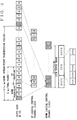
- Fig. 4 shows an example of the constitution of a logical control channel (LCCH).
- LCCH logical control channel
- this is an example in which a first slot of a TDMA frame is allocated to the logical control channel (LCCH) and an LCCH super frame is constituted by m of intermittently transmitted frames at every nTDMA frames.
- a TDMA frame of 5 [ms] is constituted by 4 slots of down (transmission) and 4 slots of up (reception) successive thereto. Further, slots constituting a down logical control channel (LCCH) are present at every nTDMA frame. That is, a down intermittent transmitting period is 5 ⁇ n [ms].
- LCCH down logical control channel
- a minimum period ( 5 ⁇ n ⁇ m [ms] ) of a down logical control channel (LCCH) designating slot positions of all of LCCH elements is defined as an LCCH super frame.
- the down logical control channel (LCCH) is constituted by a broadcast control channel (BCCH), a paging channel (PCH) and a signaling control channel (SCCH).
- BCCH is transmitted at front slots of the LCCH super frame and a position of a front of LCCH is informed by transmitting BCCH.
- an up logical control channel (LCCH) is constituted by a signaling control channel (SCCH).
- a position of a slot in the up logical control channel (LCCH) is informed from the cell station (CS) to a personal station (PS) by information elements constituting a carrier for control in a message for the broadcast information of wireless channel on BCCH.
- BCCH is a down uni-directional channel for informing broadcast control information from CS to PS.
- Information related to channel structure, system information and so on is transmitted by BCCH.
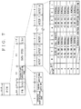
- BCCH is constituted by a preamble pattern (PR), a unique word for synchronization (UN), a channel identifier (CI), a transmission identification code, data (BCCH) and a cyclic redundancy check (CRC).
- PR preamble pattern
- UN unique word for synchronization
- CI channel identifier
- CI transmission identification code
- data BCCH
- CRC cyclic redundancy check
- the transmission identification code is constituted by an operator identification code, a paging area number and an additional ID.
- data (BCCH) is constituted by octet 1 through octet 8. Further, kind of message by octet 2 through octet 8 is shown by lower 7 bits of octet 1.
- SCCH is a point-to-point bi-directional channel for transmitting information necessary for connecting call between CS and PS. According to SCCH, independent information is transmitted to each cell.
- SCCH is constituted by a preamble pattern (PR), a unique word for synchronization (UN), a channel identifier (CI), a transmission identification code, a reception identification code, data (SCCH) and a cyclic redundancy check (CRC).
- the transmission identification code is constituted by an operator identification code, a paging area number and an additional ID and the reception identification code is constituted by a PS identification (PS-ID).
- PS-ID PS identification
- SCCH up
- Data (SCCH) is constituted by octet 1 through octet 5. Further, kind of message by octet 2 through octet 5 is shown by lower 7 bits of octet 1.
- PCH is a down uni-directional channel of point-to-multipoints for paging the same information from CS to PSs over a wide area (paging area) composed of a single cell and/or a plurality of cells.
- CS informs to PS that call is present.
- a plurality of number of PCHs (PCH1 through PCHn) is present in the LCCH super frame.
- Fig. 7 shows the constitution of PCH.
- PCH is constituted by a preamble pattern (PR), a unique word for synchronization (UN), a channel identifier (CI), a transmission identification code, data (PCH) and a cyclic redundancy check (CRC).
- the transmission identification code is constituted by an operator identification code, a paging area number and an additional ID.
- the data (PCH) is constituted by octet 1 through octet 8.
- PCH defines only a single message and therefore, PCH is not provided with an area indicating kind of message.
- kind of call service such as no call, a call service by a PS number indicated by a thirteenth digit or lower of BCD, call service by a PS number of hexadecimal seven digit or the like is displayed by 5 through 7 bits of octet 1. Further, the PS number is shown by octets 1 through 7. Further, reception instruction of a broadcast control channel (BCCH) is carried out by octet 8.
- BCCH broadcast control channel
- PS recognizes PCH to be received from a plurality of PCHs (PCH1 through PCHn) by a reception signal group number.
- the reception signal group number is calculated by Equation (1) based on PS number and content of BCCH from CS (n PCH , n GROUP , constitution of a carrier for control).
- notation n PCH designates a number of same reception signal group
- notation n GROUP designates a reception signal group factor.
- Reception signal group number (PS No.)MOD(n PCH ⁇ n GROUP ⁇ X)+1
- the system returns to its control channel receiving state and is brought into a standby state.
- the telephone (PS) 10 is shifted to intermittent receiving in which only PCH in correspondence with the calculated reception signal group number is received.
- PCH in correspondence with the calculated reception signal group number is present at every LCCH super frame and accordingly, intermittent receiving at every 1.2 seconds is formerly constituted in the standby state.
- the cell station transmits the data such as the arrival of incoming call, plural times in consideration of jamming and so on. Therefore, when the control channel is received in a good state, it has no trouble that the interval between each reception of the control channel becomes longer.
- the microcomputer 11 controls the interval between each reception of the control channel in accordance with a flowchart shown by Fig.8.
- the telephone When the telephone shifts to the standby state, the telephone is timed to the reception timing of PCH of the reception signal number calculated the above. Firstly, at step ST21, the timer 1 is started and, at step ST22, the timers 2 and 3 are also started. In this case, each of the timers 1 through 3 is constituted by the timer unit 28 and they are reset at starting operation.
- step ST23 receiving circuits such as the wireless unit 13, the digital modulating and demodulating unit 14, the TDMA processing unit 15 are brought into an ON state. Further, at step ST24, it is determined whether time period W1 has elapsed referring to the timer 2. In this case, the time period W1 is a reception time period at each time in the intermittent reception and is set to, for example, 48 ms. When the time period W1 has elapsed, at step 25, the receiving circuits are brought into an OFF state. Further, at step ST26, it is determined whether or not the control channel (PCH) has been received from the cell station while the receiving circuits stay on the ON state.
- PCH control channel
- step ST26 when the control channel (PCH) is received, at step ST27, the information for the judgment of receiving state is stored in the built-in memory.
- the information for the judgment of receiving state the information such as the intensity of electric field on the occasion of receiving the control channel (PCH), the presence or absence of an error in the received data and so on, is exemplified.
- step ST28 it is determined whether or not the PS number of PCH is mine.
- step ST29 the processing of the arrival of incoming call is carried out.
- step ST30 it is determined whether or not the power saving mode is set.
- step ST31 the timer 1 is started and the operation proceeds to step ST32.
- step ST27 it is determined whether or not the control channel is received in a good state on the basis of the information for the judgment of receiving state, which has been stored in the build-in memory at step ST27.
- the good receiving state of the control channel is determined by the information such that the intensity of electric field is high and there is no error in the received data
- step ST34 it is determined whether or not a predetermined period of time has elapsed referring to the timer 1.
- the operation proceeds to the step ST32.
- step ST33 the good receiving state is not determined, at step ST31, the timer 1 is started and then the operation proceeds to the step ST32.
- step ST32 it is determined whether or not 1.2 seconds have elapsed referring to the timer 3.
- the operation returns to the step ST22 in which the receiving circuits are brought into ON state, and then the operations described above are repeated.
- step ST35 it is determined 2.4 seconds have elapsed.
- the operation returns to the step ST22 and the timers 2 and 3 are started, and then the operations described above are repeated.
- step ST26 the control channel (PCH) is not received from the cell station while the receiving circuits stay on the ON state, out-of-synchronism with the control channel is judged and then, at step ST36, the processing of out-of-synchronism is carried out.
- PCH control channel
- the control channel (PCH) is received at every 1.2 seconds in spite of the receiving state.
- the control channel when the control channel is kept on receiving in a good state for a predetermined period of time while said control channel is received at every 1.2 seconds, said control channel is made received at every 2.4 seconds. Further, when the control channel is not received in a good state while said control channel is received at every 2.4 seconds, said control channel is promptly made received at every 1.2 seconds.
- Fig. 9 shows waveform of consumed current in the operation by the flowchart of Fig.8.
- the notation T1 designates the time when it is judged that the control channel is kept on receiving in a good state for a predetermined period of time while said control channel is received at every 1.2 seconds.
- the notation T2 designates the time when it is judged that the control channel is not received in a good state while said control channel is received at every 2.4 seconds.
- the consumed current is I1 (for example, 4ms) when the receiving circuits stay on the OFF state and the consumed current is I2 (for example, 180 ms) when the receiving circuits stay on the ON state.
- the microcomputer 11 controls the processing of out-of-synchronism at step ST36 in accordance with a flowchart shown by Fig. 10.
- Notation M designates a number of bringing about the control channel receiving state in order to establish the synchronism with the control channel (i.e., number of retrial) and notation X designates a number of out-of-synchronism during past one hour.
- step ST3 receiving circuits such as the wireless unit 13, the digital modulating and demodulating unit 14, the TDMA processing unit 15 are brought into an ON state and at step ST4, a timer is started.
- the timer is constituted by the timer unit 28 and is reset in starting operation.
- step ST5 it is determined whether a time period W2 has elapsed.
- the time period W2 is a reception time period at each time in the intermittent reception in the case of out-of-synchronism and is set to, for example, 220 ms.
- the receiving circuits are brought into an OFF state.
- step ST7 it is determined whether the synchronism with the control channel has been established by receiving the control channel from the cell station while the receiving circuits stay on the ON state.
- step ST7 When, at step ST7, it is determined that the synchronism with the control channel has not been established, at step ST8, M is incremented and, at step ST9, a timer is started. Further, at step ST10, it is determined whether a time period t1 has elapsed.
- the time period t1 is an interval between each reception of the control channel and, according to the embodiment, is set to, for example, 6 seconds.
- step ST11 it is determined whether M>N is determined where the time period t1 has elapsed.
- step ST11 When M>N is not established in step ST11, the operation returns to step ST3 and then the receiving circuits are brought into the ON state and the operations as described above are repeated.
- step ST12 the receiving circuits are brought into the ON state and then, at step ST13, a timer is started.
- step ST14 it is determined whether the time period W2 has elapsed.
- step ST15 the receiving circuits are brought into the OFF state.
- step ST16 it is determined whether the synchronism with the control channel has been established by receiving the control channel from cell station while the receiving circuits stay on the ON state.
- step ST17 a timer is started.
- step ST18 it is determined whether a time period t2 has elapsed.
- the time period t2 is an interval between each reception of control channel and, according to the embodiment, it is set to, for example, 30 seconds.
- the operation returns to the step ST12 and the receiving circuits are brought into the ON state and then the operations as described above are repeated.
- step ST7 when, at step ST7, the control channel has been established, at step ST19, the location is registered and, at step ST20, the system shifts to the standby state.
- telephone number of called party is inputted by key operation at the key input unit 24 (ten keys 48 or the like), or the speaking key 42 is operated after searching redial data or telephone book data
- telephone number data or the like are supplied to the TDMA processing unit 15 as control data by the microcomputer 11 and are transmitted to the cell station via the control channel. Thereby, telephone communication is made to the called party and a speaking state is brought about.
- the communication frequency data of the speaking channel and the data relating to the slot positions each of which are transmitted as control data from the cell station by using the control channel are supplied to the microcomputer 11 via the TDMA processing unit 15.
- the microcomputer 11 makes the transmission and reception frequency coincide with the communication frequency of the speaking channel by controlling the wireless unit 13 based on the communication frequency data and sets slots selected by the TDMA processing unit 15 on the basis of the slot position data. Accordingly, telephone communication is carried out by using the speaking channel informed from the cell station.
- the alerting sound output unit 23 is controlled by the microcomputer 11 and thus the alerting sound is outputted thereby.
- the telephone main body 40 is vibrated by controlling the vibration-generating unit 22 by the microcomputer 11.
- response data is supplied as control data from the microcomputer 11 to the TDMA processing unit 15 and is transmitted to the cell station via the control channel. Thereby, the connection with the called party is carried out and the speaking state is brought about. Also in this case, telephone communication is carried out by using the speaking channel informed from the cell station.
- compressed voice data transmitted via the speaking channel is outputted from the TDMA processing unit 15.
- the compressed voice data is supplied to the voice codec unit 16, subjected to a decoding processing and thereafter converted into an analog signal. Further, the received voice signal outputted from the voice codec unit 16 is supplied to the speaker 17 and voice is outputted from the speaker 17.
- a transmitting voice signal outputted from the microphone 18 is supplied to the voice codec unit 16, converted into a digital signal and thereafter subjected to compressed code forming processing whereby compressed voice data is formed. Further, the compressed voice data outputted from the voice codec unit 16 is supplied to the TDMA processing unit 15 and is transmitted to the called party via the speaking channel.
- the telephone when the telephone is set to an absence recording mode in the case where the call data are supplied from the TDMA processing unit 15 to the microcomputer 11 and the arrival of incoming call is detected as mentioned above, a response is made automatically after outputting alerting sound for a predetermined period of time, and the speaking state is brought about. Further, after transmitting to the calling side the response message that a received voice signal will be recorded, recording of the received voice signal is started at the voice recording and reproducing unit 21.
- character message data by a DTMF signal are transmitted from the called party during an absence recording or during a telephone communication
- key data outputted from the DTMF modulating and demodulating unit 19 is converted into character data based on control of the microcomputer 11 in reference to the conversion format storing unit 20 and the character data is written to a character message area of the non-volatile memory 25.
- the character data is written to the non-volatile memory 25 in this way, the character message of the character data is displayed on the liquid crystal display 26 and can be confirmed by operating to push " ⁇ " key of the cursor moving key 45 for a long period of time.
- control channel is made received at every 2.4 seconds when the control channel is kept on receiving for a predetermined period of time while the control channel is received at every 1.2 seconds
- the control channel may be received at every n times of 1.2 seconds such as three times, four times, in stead of 2.4 seconds.
- the interval between each reception of control channel may extend by degrees such as 1.2 seconds ⁇ 2.4 seconds ⁇ 3.6 seconds ⁇ ⁇ , at every set period of time.
- the present invention is applied to a simplified type portable telephone, the present invention is naturally applicable similarly to other portable terminal equipment which is capable of receiving intermittently the control channel transmitted from the cell station in a standby state.
- a portable terminal equipment according to the present invention is preferably applied to a portable terminal equipment of a simplified type portable telephone or the like, which is capable of receiving intermittently the control channel transmitted from the cell station in a standby state.
Landscapes
- Engineering & Computer Science (AREA)
- Computer Networks & Wireless Communication (AREA)
- Signal Processing (AREA)
- Mobile Radio Communication Systems (AREA)
Applications Claiming Priority (3)
| Application Number | Priority Date | Filing Date | Title |
|---|---|---|---|
| JP8072871A JPH09261153A (ja) | 1996-03-27 | 1996-03-27 | 携帯用端末装置 |
| JP72871/96 | 1996-03-27 | ||
| PCT/JP1997/001013 WO1997036386A1 (fr) | 1996-03-27 | 1997-03-26 | Terminal portatif |
Publications (2)
| Publication Number | Publication Date |
|---|---|
| EP0892507A1 true EP0892507A1 (fr) | 1999-01-20 |
| EP0892507A4 EP0892507A4 (fr) | 2003-04-23 |
Family
ID=13501827
Family Applications (1)
| Application Number | Title | Priority Date | Filing Date |
|---|---|---|---|
| EP97908508A Withdrawn EP0892507A4 (fr) | 1996-03-27 | 1997-03-26 | Terminal portatif |
Country Status (5)
| Country | Link |
|---|---|
| US (1) | US6324397B1 (fr) |
| EP (1) | EP0892507A4 (fr) |
| JP (1) | JPH09261153A (fr) |
| CN (1) | CN1214823A (fr) |
| WO (1) | WO1997036386A1 (fr) |
Cited By (8)
| Publication number | Priority date | Publication date | Assignee | Title |
|---|---|---|---|---|
| WO1999052312A1 (fr) * | 1998-04-07 | 1999-10-14 | Conexant Systems, Inc. | Systeme de gestion de la consommation d'une unite mobile au moyen d'une surveillance intelligente de la radiomessagerie |
| WO2003075586A1 (fr) * | 2002-03-06 | 2003-09-12 | Koninklijke Philips Electronics N.V. | Procede de reduction de consommation de courant dans un systeme de communication radio et appareil associe |
| EP1499144A1 (fr) * | 2003-07-18 | 2005-01-19 | Kabushiki Kaisha Toshiba | Terminal de communication mobile et son procédé de réception discontinu |
| EP1641294A1 (fr) * | 2004-09-27 | 2006-03-29 | Kabushiki Kaisha Toshiba | Procédé de réception discontinu pour un terminal de communication mobile et un terminal de communication mobile |
| EP1643737A1 (fr) * | 2004-09-30 | 2006-04-05 | Avaya Technology Corp. | Système pour réduire la consommation d'électricité d'un terminal mobile sans fils et pour augmenter la capacité d'un système de communication sans fils |
| US7529288B2 (en) | 2003-05-06 | 2009-05-05 | Infineon Technologies Ag | Channel qualification for an adaptive frequency hopping method by means of bit or packet error rate measurement and simultaneous field strength measurement |
| US7925904B2 (en) | 2002-08-15 | 2011-04-12 | Htc Corporation | Circuit and operating method for integrated interface of PDA and wireless communication system |
| DE10313923B4 (de) * | 2002-03-28 | 2012-07-12 | General Motors Llc ( N. D. Ges. D. Staates Delaware ) | Verfahren zur dynamischen Bestimmung von Ruhezykluswerten in einem ruhenden Fahrzeug |
Families Citing this family (23)
| Publication number | Priority date | Publication date | Assignee | Title |
|---|---|---|---|---|
| KR100303297B1 (ko) * | 1998-07-31 | 2001-09-24 | 윤종용 | 휴대폰의 전원절약방법 |
| KR100532316B1 (ko) * | 1998-12-17 | 2006-01-27 | 삼성전자주식회사 | 방송서비스에서의 단말기 배터리 소모 감소방법 |
| KR100306158B1 (ko) * | 1999-06-08 | 2001-11-01 | 윤종용 | 무선 단말기의 슬롯 인덱스 결정 방법 |
| US7023833B1 (en) | 1999-09-10 | 2006-04-04 | Pulse-Link, Inc. | Baseband wireless network for isochronous communication |
| US7088795B1 (en) | 1999-11-03 | 2006-08-08 | Pulse-Link, Inc. | Ultra wide band base band receiver |
| JP3663092B2 (ja) * | 1999-11-19 | 2005-06-22 | 三洋電機株式会社 | 無線基地局 |
| JP2001238251A (ja) | 2000-02-23 | 2001-08-31 | Nec Corp | セルラシステムの隣接キャリア周波数干渉回避方法、移動局、及び基地局制御装置 |
| US6952456B1 (en) | 2000-06-21 | 2005-10-04 | Pulse-Link, Inc. | Ultra wide band transmitter |
| US6970448B1 (en) | 2000-06-21 | 2005-11-29 | Pulse-Link, Inc. | Wireless TDMA system and method for network communications |
| KR20020046057A (ko) * | 2000-12-12 | 2002-06-20 | 구자홍 | 휴대폰의 절전 방법 |
| JP4074795B2 (ja) | 2002-09-05 | 2008-04-09 | 株式会社エヌ・ティ・ティ・ドコモ | 移動端末装置、制御装置、通信システム及び通信方法 |
| KR100514683B1 (ko) * | 2002-12-10 | 2005-09-13 | 주식회사 팬택앤큐리텔 | 휴대용 단말기 배터리 절전 방법 |
| JP4599128B2 (ja) * | 2004-03-08 | 2010-12-15 | 株式会社東芝 | 移動通信端末及びその間欠受信方法 |
| KR100604517B1 (ko) * | 2004-07-20 | 2006-07-24 | 주식회사 팬택앤큐리텔 | 휴대 단말기의 데이터 전송 및 출력장치 그리고 그 방법 |
| JP4556581B2 (ja) * | 2004-09-14 | 2010-10-06 | 日本電気株式会社 | 携帯端末装置、携帯端末制御方法及びプログラム |
| US8094595B2 (en) * | 2005-08-26 | 2012-01-10 | Qualcomm Incorporated | Method and apparatus for packet communications in wireless systems |
| KR100648067B1 (ko) * | 2005-12-10 | 2006-11-23 | 한국전자통신연구원 | 비동기식 광대역 부호 분할 다중 접속 방식에서 단말기의전력 절감 성능 개선을 위한 확장된 호출 지시자 기반의적응적 불연속 수신 방법 |
| KR100650398B1 (ko) * | 2005-12-30 | 2006-11-30 | 주식회사 팬택 | 프리앰블을 측정하여 효과적인 슬립 주기를 결정하는와이브로 단말기 및 방법 |
| JP5001693B2 (ja) * | 2007-03-22 | 2012-08-15 | 株式会社エヌ・ティ・ティ・ドコモ | 移動通信システムで使用される基地局装置及び方法 |
| US8284706B2 (en) | 2007-09-20 | 2012-10-09 | Qualcomm Incorporated | Semi-connected operations for wireless communications |
| US8984304B2 (en) | 2007-11-12 | 2015-03-17 | Marvell International Ltd. | Active idle communication system |
| JP5245789B2 (ja) * | 2008-12-12 | 2013-07-24 | 日本電気株式会社 | 移動体通信機器、及び移動体通信機器の制御方法 |
| US9762748B2 (en) * | 2009-06-08 | 2017-09-12 | Mitel Networks Corporation | Power management in an internet protocol (IP) telephone |
Family Cites Families (9)
| Publication number | Priority date | Publication date | Assignee | Title |
|---|---|---|---|---|
| JP2557889B2 (ja) * | 1987-07-03 | 1996-11-27 | 株式会社東芝 | 無線通信方式 |
| JPH04241528A (ja) | 1991-01-16 | 1992-08-28 | Fujitsu Ltd | ディジタル移動通信端末 |
| JPH05327586A (ja) | 1991-04-30 | 1993-12-10 | Nippon Telegr & Teleph Corp <Ntt> | 間欠受信方式 |
| US5507039A (en) * | 1991-05-10 | 1996-04-09 | Matsushita Electric Industrial Co., Ltd. | Mobile wireless apparatus with power consumption reduction circuitry |
| JPH0730478A (ja) | 1993-07-09 | 1995-01-31 | Nippondenso Co Ltd | ディジタルコードレス電話の省電力子機 |
| JP2600622B2 (ja) * | 1994-09-22 | 1997-04-16 | 日本電気株式会社 | Tdma方式の移動通信システムにおける下り制御信号の送信制御方法 |
| KR100229491B1 (ko) * | 1994-10-11 | 1999-11-01 | 다치카와 게이지 | 이동통신 시스템, 통신방법 및 이동국 |
| US5603093A (en) * | 1994-12-28 | 1997-02-11 | Ntt Mobile Communications Network, Inc. | Method for monitoring the state of interference by a base station of a mobile radio communication system |
| US5805666A (en) * | 1995-02-28 | 1998-09-08 | Sony Corporation | Method of and apparatus for diagnosing personal communication system |
-
1996
- 1996-03-27 JP JP8072871A patent/JPH09261153A/ja active Pending
-
1997
- 1997-03-26 CN CN97193341A patent/CN1214823A/zh active Pending
- 1997-03-26 US US09/155,267 patent/US6324397B1/en not_active Expired - Fee Related
- 1997-03-26 WO PCT/JP1997/001013 patent/WO1997036386A1/fr not_active Ceased
- 1997-03-26 EP EP97908508A patent/EP0892507A4/fr not_active Withdrawn
Cited By (13)
| Publication number | Priority date | Publication date | Assignee | Title |
|---|---|---|---|---|
| US6240288B1 (en) | 1998-04-07 | 2001-05-29 | Conexant Systems, Inc. | Power management system for a mobile unit by intelligent page monitoring |
| WO1999052312A1 (fr) * | 1998-04-07 | 1999-10-14 | Conexant Systems, Inc. | Systeme de gestion de la consommation d'une unite mobile au moyen d'une surveillance intelligente de la radiomessagerie |
| WO2003075586A1 (fr) * | 2002-03-06 | 2003-09-12 | Koninklijke Philips Electronics N.V. | Procede de reduction de consommation de courant dans un systeme de communication radio et appareil associe |
| DE10313923B4 (de) * | 2002-03-28 | 2012-07-12 | General Motors Llc ( N. D. Ges. D. Staates Delaware ) | Verfahren zur dynamischen Bestimmung von Ruhezykluswerten in einem ruhenden Fahrzeug |
| US7925904B2 (en) | 2002-08-15 | 2011-04-12 | Htc Corporation | Circuit and operating method for integrated interface of PDA and wireless communication system |
| US8417977B2 (en) | 2002-08-15 | 2013-04-09 | Htc Corporation | Operating method for integrated interface of PDA and wireless communication system |
| US8537877B2 (en) | 2003-05-06 | 2013-09-17 | Intel Mobile Communications GmbH | Channel qualification for an adaptive frequency hopping method by means of bit or packet error rate measurement and simultaneous field strength measurement |
| US7529288B2 (en) | 2003-05-06 | 2009-05-05 | Infineon Technologies Ag | Channel qualification for an adaptive frequency hopping method by means of bit or packet error rate measurement and simultaneous field strength measurement |
| EP1499144A1 (fr) * | 2003-07-18 | 2005-01-19 | Kabushiki Kaisha Toshiba | Terminal de communication mobile et son procédé de réception discontinu |
| US7463900B2 (en) | 2004-09-27 | 2008-12-09 | Kabushiki Kaisha Toshiba | Discontinuous reception method for mobile communication terminal device and mobile communication terminal device |
| EP1641294A1 (fr) * | 2004-09-27 | 2006-03-29 | Kabushiki Kaisha Toshiba | Procédé de réception discontinu pour un terminal de communication mobile et un terminal de communication mobile |
| EP1643737A1 (fr) * | 2004-09-30 | 2006-04-05 | Avaya Technology Corp. | Système pour réduire la consommation d'électricité d'un terminal mobile sans fils et pour augmenter la capacité d'un système de communication sans fils |
| US9178975B2 (en) | 2004-09-30 | 2015-11-03 | Avaya Inc. | System and method for reducing power consumption of a wireless terminal and increasing capacity of a wireless communication system |
Also Published As
| Publication number | Publication date |
|---|---|
| CN1214823A (zh) | 1999-04-21 |
| EP0892507A4 (fr) | 2003-04-23 |
| JPH09261153A (ja) | 1997-10-03 |
| US6324397B1 (en) | 2001-11-27 |
| WO1997036386A1 (fr) | 1997-10-02 |
Similar Documents
| Publication | Publication Date | Title |
|---|---|---|
| EP0892507A1 (fr) | Terminal portatif | |
| KR950013309B1 (ko) | 통신 유닛에서 전력 소모를 감소시키는 방법 | |
| US5636243A (en) | Interterminal direct communication in digital mobile communication system | |
| US5995844A (en) | Wireless telephone system | |
| EP0891065B1 (fr) | Terminal portatif | |
| US6411808B1 (en) | Portable terminal equipment | |
| JP3951416B2 (ja) | 通信端末装置 | |
| EP1045532A1 (fr) | Terminal de telecommunication | |
| JP2000115827A (ja) | 通信端末装置 | |
| JPH11266329A (ja) | 情報提供システムおよびそれに使用される通信端末装置 | |
| JPH1169409A (ja) | 無線通信携帯端末装置 | |
| JPH1032876A (ja) | 携帯用端末装置 | |
| JP2001169033A (ja) | 情報処理装置および情報処理方法、並びに通信端末装置 | |
| JP3433605B2 (ja) | 携帯用端末装置 | |
| JPH1168916A (ja) | 通信端末装置 | |
| JPH1032867A (ja) | 携帯用端末装置 | |
| JPH09307961A (ja) | 携帯用端末装置 | |
| JP2001169000A (ja) | 通信端末装置 | |
| JPH1028286A (ja) | 携帯用端末装置 | |
| JPH10107927A (ja) | 通信端末 | |
| JPH1094031A (ja) | 携帯用端末装置 | |
| JP2001168999A (ja) | 情報処理装置および情報処理方法 | |
| JP2001169354A (ja) | 通信端末装置および基地局、並びにそれを使用する通信システム | |
| JPH1094052A (ja) | 通信装置、通信機および通信方法 | |
| HK1019672A (en) | Portable terminal equipment |
Legal Events
| Date | Code | Title | Description |
|---|---|---|---|
| PUAI | Public reference made under article 153(3) epc to a published international application that has entered the european phase |
Free format text: ORIGINAL CODE: 0009012 |
|
| 17P | Request for examination filed |
Effective date: 19981020 |
|
| AK | Designated contracting states |
Kind code of ref document: A1 Designated state(s): DE FR GB NL SE |
|
| A4 | Supplementary search report drawn up and despatched |
Effective date: 20030307 |
|
| STAA | Information on the status of an ep patent application or granted ep patent |
Free format text: STATUS: THE APPLICATION HAS BEEN WITHDRAWN |
|
| 18W | Application withdrawn |
Effective date: 20030423 |