EP0893536A2 - Cylindre de tamissage et son procédé de fabrication - Google Patents
Cylindre de tamissage et son procédé de fabrication Download PDFInfo
- Publication number
- EP0893536A2 EP0893536A2 EP98401832A EP98401832A EP0893536A2 EP 0893536 A2 EP0893536 A2 EP 0893536A2 EP 98401832 A EP98401832 A EP 98401832A EP 98401832 A EP98401832 A EP 98401832A EP 0893536 A2 EP0893536 A2 EP 0893536A2
- Authority
- EP
- European Patent Office
- Prior art keywords
- screen
- sections
- screen cylinder
- modular
- grooves
- Prior art date
- Legal status (The legal status is an assumption and is not a legal conclusion. Google has not performed a legal analysis and makes no representation as to the accuracy of the status listed.)
- Withdrawn
Links
Images


Classifications
-
- D—TEXTILES; PAPER
- D21—PAPER-MAKING; PRODUCTION OF CELLULOSE
- D21D—TREATMENT OF THE MATERIALS BEFORE PASSING TO THE PAPER-MAKING MACHINE
- D21D5/00—Purification of the pulp suspension by mechanical means; Apparatus therefor
- D21D5/02—Straining or screening the pulp
- D21D5/16—Cylinders and plates for screens
Definitions
- the present invention relates to a screen cylinder intended for use in screening wood pulp and other fibrous fluid suspensions for removing foreign particles from a pulp slurry, and a method for manufacturing the apparatus. More particularly, the apparatus and method relate to rebuildable screen cylinders for screening thick stock or thick pulp slurry within the pulp and paper industry. Still more particularly, the apparatus and method relate to improved screen cylinders that are less expensive to manufacture and provide increased wear life and durability as compared to similar screen baskets known heretofore.
- Screens are used to separate acceptable papermaking fiber from unacceptable constituents of a slurry of pulp fiber in preparing the wood fiber for the papermaking process.
- a slurry of pulp flows through a perforate cylindrical screen plate or basket which may be smooth, or which may have a contoured surface facing toward the stock flowing through the screen cylinder.
- the screen plate openings are formed in different hole or hole and slot combinations for optimizing screening performance.
- pulsations are generated in the slurry such as by passing a hydrofoil-shaped member or rotor past the screen plate.
- Screen cylinders used in pulp and paper mills are subjected to heavy pressure loads.
- a screen cylinder or a screen plate which generally is a basket-shaped member surrounding a rotor, so that it can withstand the pressures experienced in a pressurized screen cylinder, it has been the accepted practice to provide thick-walled screen plates or baskets which are machined to present the desired screening surface, or thin-walled formed screen plates or baskets with reinforcing rods.
- a thick-walled screen cylinder is described in U.S. Patent No. 3,664,502.
- Screen cylinders of the type described in this patent are formed of a metal plate rolled and welded in tubular form and provided with a multiplicity of screening openings.
- relatively heavy gauge metal is used, such as 1/8" to 5/16" stainless steel.
- a weld seam is used to connect the ends of the metal plate.
- a welding fixture In order to perform the welding operation, a welding fixture must be utilized to hold the rolled screen plate in proper position to perform the weld. The weld seam leaves a rough, abrasive surface on the inside diameter of the rolled screen plate.
- screens of this type that are rolled and welded into tubular form must undergo grinding operations to smooth out the interior surface of the screen plate. After the grinding operations, the screen cylinder is machined in the round or rolled condition to provide a finished interior surface.
- the type of one-piece screen described above has been expensive to use and maintain in that, even if only a small area of screen is damaged, the entire screen plate, which includes the screening surface, mounting bodies and support members must be replaced, thereby presenting a costly operating experience.
- the prior art screens described above require that the screen cylinder ends be seam welded when rolled into cylindrical form.
- This manufacturing method of construction leads to screen failure at the welded seam when the screen is used under normal operating conditions.
- the welded seam joint constrains the cylinder screen in the round condition under mechanical stress, and the welding process induces thermal stresses in the screen at locations near the weld seam.
- the weld seam creates a heat-affected zone at and near the seam which becomes very brittle.
- the screen is subject to failure at or near the weld seam.
- stress relieving is performed in one of two ways to prevent or reduce the stresses introduced into these prior art screens. The first method involves vibratory stress conditioning of the screen, and the second method involves thermal stress relieving the screen by heat treatment.
- U.S. Patent No. 4,954,249 describes an improved screen over the screens described above as used in the pulp and paper industry.
- Beloit Corporation sells and markets screen cylinders according to this patent under the trademark BelWaveTM.
- the modular screen plate structure of Beloit's BelWaveTM screen simplifies screen plate changing and eliminates the need to change an entire screen plate when only a portion of the plate is damaged or worn.
- One of the features of Beloit's BelWaveTM screen plate is utilizing corrugated, thin-walled screen material in order to avoid the attendant difficulties of machining thick-walled screen plates and to reduce the cost associated with manufacturing thick-walled screen plates.
- the modular, cylindrically-shaped screens also reduce the number of welding operations needed to create cylindrical screens by positioning and connecting modular screen sections into grooves located in support rings.
- the modular screen sections are formed into a corrugated pattern and then rolled into cylindrical form.
- One end of the corrugated screen plate section overlaps the other end of the corrugated section and a weld seam is not required to hold the ends together because the corrugated thin-walled section is pressed into the grooves located in adjacent support rings.
- Beloit's BelWaveTM screen cylinder has been and continues to be an improved screen plate for the pulp and paper industry, in certain thick stock or slurry screening operations, the thin, corrugated screening media is subject to impact failure.
- a novel, modular, thick-walled, smooth or contoured screen cylinder and a method of manufacturing this screen cylinder is described below.
- the thick-walled, smooth or contoured surface screen cylinder is capable of withstanding the destructive elements found in thick slurry pulp and paper screening environments.
- the problems associated with using a weld seam for a screen cylinder or section where rolled ends of the screen cylinder or section meet has been obviated by the present invention.
- a lap joint according to the present invention is used to connect the ends of a screen cylinder or section when the screen is rolled into cylindrical shape. The lap joint is machined into the ends of the screen cylinder or section before it is rolled into final form.
- the lap joint connection eliminates any need to weld the ends of the screen cylinder or section together; which, consequently, eliminates any grinding or machining operation on the inside surface of the screen after it has been rolled into cylindrical shape. Additionally, because the lap joint allows for an overlapping floating design, tight manufacturing tolerances needed for prior art screens are eliminated.
- the nonwelded construction of the screen will prevent any slot and hole distortion encountered in the heat zones of the currently used welded screens.
- the nonwelded construction of the screen also improves operational strength and eliminates failures that are associated with welded screen cylinders.
- a further feature of the invention is that the lap joint does not constrain the screen cylinder or section after rolling, which in turn reduces the mechanical stresses induced into prior art screen cylinders from the current rolling and welding operations. Furthermore, the lap joint of the current invention is beneficial in that it eliminates the heat-affected zone created by the prior art welding operations and all of the thermal stresses associated with prior art welding operations.
- a still further feature of the invention is to eliminate expensive weld fixtures currently necessary in order to assemble screens as described herein.
- An additional feature is to eliminate costly grinding operations utilized in manufacturing screen cylinders because of current welding processes. Eliminating welding operations conducted on or near the interior surface of a screen eliminates grinding and finish machining operations on the interior surface of the screen.
- Another feature is to reduce high-tolerance machining operations in connection with manufacturing screen cylinders.
- novel screen cylinder described herein is that it is capable of withstanding the destructive environments found in thick slurry or pulp screening applications in the pulp and paper industry.
- a still further feature of the screen cylinder according to the present invention is that when used as a replacement for earlier modular designs, the novel screen cylinder provides greater capacity in the same screen apparatus.
- Figure 1 is a perspective view, with portions broken away, illustrating a screening apparatus having a prior art modular cylindrical screen cylinder sold by Beloit Corporation under the trademark BelWaveTM.
- Figure 2 is an enlarged fragmentary, sectional view taken substantially along line II-II of Figure 1.
- Figure 3 is a side view, partly in section, of another prior art screen cylinder.
- FIG. 4 is an enlarged, fragmentary view of the region designated "4" in Figure 3.
- Figure 5 shows a screen cylinder according to the present invention.
- Figure 6 shows a partially assembled screen cylinder of the present invention.
- Figure 7 is a cross-sectional detail of a screen section lap joint according to the present invention.
- Figure 8 is a top cross-sectional view of a rolled screen section depicting the lap joint according to the invention.
- Figure 9 is a perspective view of the screen cylinder of Figure 5, with portions broken away, illustrating details of the assembly of one embodiment according to the present invention.
- Figure 5 shows a screen cylinder according to the present invention.
- Figure 8 shows a lap joint 42, described more fully below, as used in the screen cylinder of the present invention.
- Screen cylinders of the type described according to the present invention that utilize the lap joint 42, shown in Figure 8, are intended to replace the prior art screens described in Figures 1-4.
- Figure 1 illustrates a prior art screening apparatus 1 wherein previously treated pulp is screened to remove foreign elements such as sheaves, bark, knots, particles of wood, dirt, glass, plastic and the like.
- a screen plate assembly is shown at 10, defining in the apparatus 1 an interior chamber 2 where the pulp to be screened flows in and an exterior chamber 3 where the screened pulp flows out after passing through the screen plate assembly.
- the assembly is enclosed in a housing 4 which has an inlet (not shown) for the entrance of pulp to be screened into the chamber 2, and an outlet (not shown) leading from the 20 chamber 2 for the foreign material such as the sheaves, bark and dirt.
- the accepted pulp flows out through an outlet 5.
- the screen plate assembly 1 is stationary within the housing 4, and for aid in passing the liquid stock with pulp through the screen plate, and to help inhibit plugging, hydrofoils 6 are mounted for rotation within the cylindrical screen plate assembly.
- the hydrofoils 6 are supported on arms of a rotary driven shaft 7, and rotate in a clockwise direction, as viewed in Figure 1.
- the hydrofoils shown are merely illustrative of a suitable type, and it should be understood that the present invention can be used for screen plates of various types for various pulse, turbulence and combination pulse and turbulence generating rotors.
- the prior art screen plate assembly 1 includes cylindrical, thin-walled, corrugated screen sections 8 and 9 which, without support, are essentially flexible and require rigidifying or strengthening for use in the pressurized environment of screen apparatus 1.
- the necessary support and strengthening is provided by end rings 11 and 12 and an intermediate support ring 13.
- Each of the rings has grooves such as illustrated by the grooves 14 and 15 in the ring 13 shown in Figure 2.
- the grooves 14 and 15 are circular to hold the screen sections in a substantially cylindrical shape.
- the grooves 14 and 15 have a radial dimension substantially equal to the radial thickness of the shaped screen plates.
- the screen plates according to this prior art device are formed from relatively thin material formed in various shapes or contours.
- each of the shaped screen plates is positioned into the grooves in the end rings 11 or 12 and the intermediate ring 13, and the rings are pulled together to force the screen plates into the grooves 14 and 15.
- axially extending rods 16 are provided, spaced circumferentially from each other, and the rods are provided at their ends with threads and nuts 17 so that the nuts can be tightened to pull the end rings toward each other and force the ends of the screen plates into the respective grooves.
- the grooves 14 and 15 are tapered so that the slot becomes narrower in an inward direction toward the bottom of the grooves, as indicated by the illustration shown in Figure 2.
- the screen plates When the rods are tightened, the screen plates are pushed tightly into the tapered grooves so that the screen plates are held firmly in a fixed, circumferential position.
- the screens can be longer or shorter, and additional reinforcing intermediate rings such as 13 may be employed between the ends of each of the adjacent screens.
- Screening openings such as 18 and 19 extend through the thin-walled, corrugated prior art screen material, as shown in the screen sections 8 and 9 in Figure 2.
- Screening openings such as 18 and 19 extend through the thin-walled, corrugated prior art screen material, as shown in the screen sections 8 and 9 in Figure 2.
- different combinations of slots or holes may be employed, and the thin material used in this prior art screen plate assembly can be provided with holes or slots of different sizes and shapes through various manufacturing techniques.
- the damaged section can be replaced by loosening the axial tie rods and replacing or exchanging the damaged section.
- This also enables replacement with substitute sections of different hole or slot arrangements so that, with a given piece of screening machinery, different screening operations can be achieved through easy replacement of screen sections.
- access to the interior of the housing 4 is readily afforded by removal of the end plate 4a through removal of the bolts 4b. This permits withdrawal of the screen assembly for ready exchange or replacement of the screen sections.
- the screen sections 8 and 9 are formed into a variety of undulated patterns by simple bending and forming techniques, as described in U.S. Patent No. 5,023,986.
- FIGS 3 and 4 show another prior art screen cylinder or drum 20 that comprises a plurality of adjacent cylindrical screen members 21 between which there is a gap 22.
- the screen drum there are a plurality of stiffening rings 23 spaced apart, which have been fitted with a flange-like projecting part 24 that extends between end surfaces 26 of the cylindrical screen members.
- Cylindrical surfaces 25 of the stiffening ring 23 are of the same size or slightly larger in diameter than the outer surface 27 of the cylindrical screen member so that, when assembling a screen drum, they can function as guiding surfaces for the ends 28 of the cylindrical screen member.
- the cylindrical screen members and the stiffening ring are attached by a weld joint 29, connecting the projecting part of the stiffening ring and the ends of the cylindrical screen member and filling the gap between the cylindrical screen members.
- FIG 5 illustrates a modular, thick-walled screen cylinder 30 according to the present invention that is an improvement to the screen cylinders shown in Figures 1-4. Additionally, the screen cylinder of the present invention can be used as a replacement for prior art screen cylinders in most common pulp and paper screen apparatuses.
- the screen cylinder 30 fits into a screening apparatus housing having similar inlets and outlets as those described for the screening apparatus 1 shown in Figure 1. Also, a hydrofoil and drive shaft similar to that used in the screen of Figure 1 is used for the screen cylinder of the present invention.
- the modular screen cylinder of the present invention includes cylindrical screen sections 31 which are made from smooth or contoured, relatively thick, polished 316 stainless steel or other suitable alloy. Occasionally, if the environment requires it, the screen sections or media 31 are chrome plated to provide further wear and corrosion resistance.
- the screen sections 31 can have a variety of hole or slot sizes and/or various contours.
- the modular screen cylinder 30 includes end rings 33 and 34 and intermediate support rings 35.
- the screen cylinder support rings 35 are made of 17-4ph stainless steel, and treated to C-40 material specification, but can also be made from other suitable alloys.
- each of the support rings 35 has grooves 36 and 37.
- End rings 33 and 34 each have a groove which is similar to the grooves 36 and 37 of support ring 35.
- the grooves 36 and 37 are circular to hold the screen sections in substantially cylindrical shape.
- each of the shaped screen sections 31 is positioned into the grooves 36 and 37 of the respective rings.
- the modular screen cylinder assembly 30 is pulled together to position the screen sections into the grooves.
- axially extending stainless steel tie rods 38 are provided, spaced circumferentially from each other, and the rods are provided at their ends with threads and nuts 39 so that the nuts can be tightened to pull the end rings toward each other and force the ends of the screen sections into the respective grooves.
- tie rods are not used; rather, screen sections 31 are held firmly in place via grooves 36 and 37 by welding the outside surface 46 of the screen sections 31 to the support rings 35 or end rings 33 or 34.
- the minimal amount of welding necessary on the outside surface of the screen in order to firmly hold the screen cylinder together does not affect the inside screening surface and does not induce any significant amount of thermal stresses into the screen section. Eliminating the weld used on the inside of a cylinder to hold it together eliminates the need to grind and finish machine the inside surface of the screen as is currently done in prior art screen cylinders.
- Figure 6 shows a partially assembled screen cylinder according to the present invention.
- Screen sections 31 fit into the grooves 36 and 37 and are stacked one on top of the other until a complete cylindrical screen is formed.
- Tie rods 38 hold the screen cylinder 30 together.
- the tie rods 38 are not used; rather, the sections 31 are welded directly to the rings.
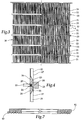
- Figure 7 shows a cross-section of a screen section 31 before it is rolled into cylindrical shape.
- Ends 40 and 41 of the section 31 contain a machined joint that, when fitted together in a rolled shape, form a lap joint 42, as shown in Figure 8, according to the present invention.
- the lap joint 42 is of a floating design, meaning that when the screen section 31 is rolled into cylindrical form, it will align itself circumferentially with the rings.
- the rings are formed into cylinder shape. Screen sections 31 will conform to the cylindrical shape of the rings when fitted into the grooves of the rings because of the floating design of the lap joint 42.
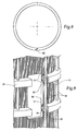
- Figure 9 shows a partially broken away section of screen section 31 and further depicts how the screen sections fit with the grooves of the rings.
- the screen section 31 has top and bottom portions 43 and 44.
- the top and bottom parts have ring groove ears 45.
- the groove ears 45 fit into the grooves 36 and 37 of the rings 35, or rings 33 or 34, when assembled together.
- the groove ears and grooves are shown with particular shapes, e.g., tongue and groove connection, the groove ears and grooves can be of many different shapes and sizes.
- the prior art screen shown in Figure 1 is assembled in the following manner. First, the screen sections are machine drilled or slotted while in a flat configuration or formed through mechanical bending and shaping. Once the sections are drilled, slotted or formed, the individual screen sections are rolled into cylindrical shape. After the sections are rolled, if necessary, the ends of the sections are machined so they will fit into the grooves of the rings. After the screen sections are formed, the screen cylinder is assembled by placing the sections into the grooves of the rings stacking one section on top of another. Because the grooves are of a tapered design, in order to snuggly fit the ends of the sections into the grooves and bottom out the ends of the sections in the grooves, a 100-ton press is used to force the screen media into the grooves. Tie rods are used to firmly hold the screen cylinder assembly together.
- the prior art screen shown in Figure 3 is assembled in the following manner. First, the holes or slots are drilled or machined into the section while the section is in a flat configuration. The section is then rolled into cylindrical form. Once rolled, a welding fixture is utilized in order to hold the section together while the ends of the section are seam welded together. The screen sections are assembled one on top of the other by connecting each section to each other via the use of a stiffening ring and a weld. Once all the welding operations are finished, the inside surface of the screen cylinder must be ground and finish machined.
- the modular screen cylinder of the present invention utilizes thick, smooth or contoured screen sections and eliminates welding the ends of screen sections together. Eliminating the weld seam eliminates the need for welding fixtures, inside diameter grinding operations and finish machining procedures of prior art screens. Because welding the seams is eliminated, the drilled or slotted holes are not affected, which provides for an improved screening surface. All of which greatly reduces the overall cost associated with manufacturing screen cylinders. Even more importantly, eliminating the weld seam improves the operational strength of the screen cylinder and eliminates the possibility of screen cylinder failures at or near a weld seam.
- the modular screen assembly according to the present invention eliminates the need for special weld fixtures which are required to hold individual screen media and rings together during the welding process for the present prior art conventional screen cylinders.
- the screen media has groove ears 45 machined onto the screen sections 31, and the rings are machined with mating grooves 36 and 37, as shown in Figure 9.
- the screen media groove ears are then placed into the mating ring grooves as shown in Figures 6, 7 and 9. This is repeated until the entire screen assembly has been stacked to its finished size, see Figs. 5 and 6.
- the ring grooves 36 and 37 work as integral devices which lock and hold the screen media in place to the exact inside screen cylinder diameter specifications.
- the modular screen has no inside diameter welding at the groove ears and groove interface, and all parts are machined to their finished dimensions prior to assembly. Therefore, all finish grinding and finish machining on the inside diameter of the screen cylinder are eliminated.
- Lap joint ends 40 and 41 are machined in the flat as shown in Figure 7 on opposing sides of a screen section.
- the lap joint creates an overlapped mechanical joint when the screen section is rolled into a cylinder shape as shown in Figure 8.
- This overlapping mechanical lap joint allows for ease of assembly because of the tolerances associated with generating the lap. All welding is eliminated at the inside diameter of the screen media seam. Thus, this eliminates any need to grind the inside diameter to ensure proper finished dimensions and surface finish. Because the lap joint is a floating design joint, this allows for less costly machine tolerances.
- the lap joint is designed with enough tolerance for slippage or movement so that rolled screen media will expand or contract as needed to properly locate itself, cylindrically, with the grooves of the respective rings.
- the inside diameter of the ring groove is the controlling factor for the finished screen cylinder's inside dimensions.
- the lap joint will remain fixed once the screen media sections are placed into the captive ring grooves. After the cylinder is completely assembled, the tie rods hold the assembly together. Because of the shape of the grooves and groove ears, assembly can be accomplished without the use of a large press machine, as is needed with Beloit's BelWaveTM design. In those applications where tie rods are not necessary, the outside surface of the screen sections can be lightly welded to the support rings. These light welds are unlike the large weld seam of the prior art screens.
- the system of interchangeable cylindrical screen members is essential to modular screen technology.
- the screening media section is a replaceable hoop that fits securely into a groove in a support ring.
- High strength stainless steel tie rods hold the cylinder together in one embodiment of the invention. Damaged hoops can be replaced one at a time for a fraction of the cost of replacing the entire cylinder.
- the screen cylinder frame of rings and tie rods can be reused again and again.
- the modular screen section allows the use of varying screen media within a single cylinder. For example, because the concentration of large debris increases as flow moves further down the cylinder, greater spacing between the screening holes toward the cylinder's outlet end allows for avoiding plugging and keeping the screen apparatus operating smoothly. Additionally, because of the nonwelded construction, the slotted cylinders have approximately 5 percent more open area than conventional cylinders, resulting in increased screening capacity. The precise tongue and groove connection between the screening media hoop and the support rings ensures a solid seal between components.
Landscapes
- Engineering & Computer Science (AREA)
- Mechanical Engineering (AREA)
- Paper (AREA)
Applications Claiming Priority (2)
| Application Number | Priority Date | Filing Date | Title |
|---|---|---|---|
| US08/897,541 US5954956A (en) | 1997-07-22 | 1997-07-22 | Modular screen cylinder and a method for its manufacture |
| US897541 | 1997-07-22 |
Publications (2)
| Publication Number | Publication Date |
|---|---|
| EP0893536A2 true EP0893536A2 (fr) | 1999-01-27 |
| EP0893536A3 EP0893536A3 (fr) | 1999-05-19 |
Family
ID=25408034
Family Applications (1)
| Application Number | Title | Priority Date | Filing Date |
|---|---|---|---|
| EP98401832A Withdrawn EP0893536A3 (fr) | 1997-07-22 | 1998-07-20 | Cylindre de tamissage et son procédé de fabrication |
Country Status (3)
| Country | Link |
|---|---|
| US (1) | US5954956A (fr) |
| EP (1) | EP0893536A3 (fr) |
| CA (1) | CA2240101C (fr) |
Cited By (4)
| Publication number | Priority date | Publication date | Assignee | Title |
|---|---|---|---|---|
| EP1057927A1 (fr) * | 1999-06-04 | 2000-12-06 | E & M LAMORT | Tamis cylindrique, notamment pour la pate à papier |
| JP2009195902A (ja) * | 2008-02-21 | 2009-09-03 | Weatherford Lamb Inc | 円筒状スクリーンを形成するために複数パネルを相互にスプライス接続するための構造 |
| US9023456B2 (en) | 2011-03-18 | 2015-05-05 | Bilfinger Water Technologies, Inc. | Profiled wire screen for process flow and other applications |
| WO2026085586A1 (fr) * | 2024-10-25 | 2026-04-30 | GoldQuip Pty Ltd | Système de tamis modulaire |
Families Citing this family (20)
| Publication number | Priority date | Publication date | Assignee | Title |
|---|---|---|---|---|
| US5718826A (en) * | 1995-05-26 | 1998-02-17 | Cae Screen Plates, Inc. | Screen and method of manufacture |
| US6138838A (en) | 1998-05-29 | 2000-10-31 | J&L Fiber Services, Inc. | Screen media and a screening passage therefore |
| FR2809029B1 (fr) * | 2000-05-16 | 2002-06-21 | Johnson Filtration Systems | Procede de fabrication d'un panier mecanique de filtration |
| DE10052715A1 (de) * | 2000-10-24 | 2002-05-02 | Fiedler Heinrich Gmbh | Spaltsiebanordnung |
| US6460757B1 (en) | 2000-11-14 | 2002-10-08 | Newscreen As | Apparatus and method for forming slotted wire screens |
| CA2444486C (fr) * | 2001-04-16 | 2013-04-02 | J & L Fiber Services, Inc. | Epurateur a pate a papier et son procede |
| SE519079C2 (sv) * | 2001-05-30 | 2003-01-07 | Metso Paper Inc | Sil för silning av massasuspensioner innefattande en stödring med konisk yta |
| DE10148192A1 (de) * | 2001-09-28 | 2003-04-17 | Fiedler Heinrich Gmbh | Spaltsiebanordnung |
| AT413110B (de) * | 2003-10-15 | 2005-11-15 | Andritz Ag Maschf | Sortierer |
| ITVI20040139A1 (it) * | 2004-06-10 | 2004-09-10 | Comer Spa | Metodo per la fabbricazione di cestelli filtranti di fibre in sospensione acquosa e cestello filtrante fabbricato mediante detto metodo |
| US7306176B1 (en) | 2004-06-21 | 2007-12-11 | Prince Industries, Inc. | Compression assembly |
| CA2609881C (fr) * | 2005-05-09 | 2012-05-29 | Marc-Andre Hetu | Panier de tamis a barres profilees remplacables |
| ITVI20070209A1 (it) * | 2007-07-31 | 2009-02-01 | Comer Spa | Cestello filtrante perfezionato per fibre in sospensione acquosa |
| CA2705475C (fr) * | 2007-11-14 | 2015-05-05 | Filtration Fibrewall Inc. | Panier epurateur |
| US8028691B2 (en) * | 2008-10-27 | 2011-10-04 | Johnson Screens, Inc. | Passive solar wire screens for buildings |
| KR101107783B1 (ko) | 2011-12-09 | 2012-02-14 | 주식회사 더존이텍 | 와이어 스크린 |
| US11118584B2 (en) | 2016-06-29 | 2021-09-14 | Itt Manufacturing Enterprises Llc | Ring section pump having intermediate tie rod combination |
| WO2018134835A1 (fr) * | 2017-01-21 | 2018-07-26 | Pawar Balraj | Tambour modulaire et son procédé de fabrication |
| DE102018007294A1 (de) * | 2018-09-14 | 2020-03-19 | Guntram Krettek | Verfahren zum Fixieren eines Bleches und damit hergestellte Filtereinrichtung |
| US20220355225A1 (en) * | 2021-05-10 | 2022-11-10 | Lyco Manufacturing Inc. | Externally Fed Screen for Filtration |
Family Cites Families (77)
| Publication number | Priority date | Publication date | Assignee | Title |
|---|---|---|---|---|
| US3217386A (en) * | 1965-11-16 | Yarn transfer drum | ||
| US438822A (en) * | 1890-10-21 | Geoege philion | ||
| US1151131A (en) * | 1914-07-25 | 1915-08-24 | Christopher F Starliper | Shaft-collar. |
| US2116584A (en) * | 1936-10-05 | 1938-05-10 | Shelby Leon | T-lock joint |
| US2353444A (en) * | 1939-08-10 | 1944-07-11 | Conradty Ottmar | Connection of carbon bodies |
| US2391302A (en) * | 1942-01-10 | 1945-12-18 | Evans William James | Means for fixing pulleys and the like to shafts |
| US3091844A (en) * | 1960-05-16 | 1963-06-04 | Allegheny Ludlum Steel | Method of making flexible joints |
| GB995532A (en) * | 1963-04-26 | 1965-06-16 | Herbert Alfred Merges | Screen drum |
| US3399516A (en) * | 1965-06-02 | 1968-09-03 | Wix Corp | Impregnated fiber air filter and method of making same |
| US3387708A (en) * | 1966-01-24 | 1968-06-11 | Beloit Corp | Paper machine screen |
| DE1807714C2 (de) * | 1968-11-08 | 1971-01-04 | Degussa | Verfahren und Vorrichtung zum kontinuierlichen Vorverdichten sowie gleichzeitigen Formen von feinteiligen Stoffen |
| US4074985A (en) * | 1976-05-04 | 1978-02-21 | Raymond Zeno Willas | Air filter |
| FI57986C (fi) * | 1979-02-28 | 1980-11-10 | Ahlstroem Oy | Siltrumma och saett att tillverka denna |
| US4213823A (en) * | 1979-04-26 | 1980-07-22 | Beloit Corporation | Paper making machine screen with staggered foils |
| WO1981000375A1 (fr) * | 1979-08-09 | 1981-02-19 | Tarmac Ind Holdings Ltd | Procede et appareil de production de materiau en feuille composite |
| SE441108B (sv) * | 1980-01-24 | 1985-09-09 | Celleco Ab | Siltrumma for silning av cellulosamassa och liknande |
| US4316768A (en) * | 1980-07-18 | 1982-02-23 | Beloit Corporation | Pulse free stock screen and combination pump |
| JPS5832275B2 (ja) * | 1980-12-11 | 1983-07-12 | 永岡金網株式会社 | スクリ−ン |
| US4348284A (en) * | 1981-01-09 | 1982-09-07 | Multi-Metal Wire Cloth Inc. | Filter leaf construction |
| US4396502A (en) * | 1982-03-18 | 1983-08-02 | Beloit Corporation | Screening apparatus for a papermaking machine |
| US4462900A (en) * | 1982-07-16 | 1984-07-31 | Beloit Corporation | Centrifugal pulp screening device and method |
| SE436287B (sv) * | 1983-04-12 | 1984-11-26 | Sunds Defibrator | Sett och anordning for framstellning av fibermassa fran lignocellulosahaltigt material |
| US4538734A (en) * | 1983-07-14 | 1985-09-03 | Beloit Corporation | Disk screen apparatus, disk assemblies and method |
| FR2572950B1 (fr) * | 1984-11-12 | 1987-01-23 | Lamort E & M | Perfectionnements aux tamis pour epurateurs et a leur mode de fabrication |
| US4663030A (en) * | 1985-02-08 | 1987-05-05 | The Black Clawson Company | Disk rotor for selectifier screen |
| SE453674B (sv) * | 1985-06-18 | 1988-02-22 | Kamyr Ab | Anordning for silning av foretredesvis medelkonsistensmassa |
| US4981583A (en) * | 1985-06-20 | 1991-01-01 | Beloit Corporation | High consistency pressure screen and method of separating accepts and rejects |
| US5110456A (en) * | 1985-06-20 | 1992-05-05 | Beloit Corporation | High consistency pressure screen and method of separating accepts and rejects |
| JPS62156493A (ja) * | 1985-12-27 | 1987-07-11 | 永岡金網株式会社 | 二重筒スクリ−ン |
| MX169011B (es) * | 1986-04-24 | 1993-06-17 | Beloit Corp | Mejoras en filtro de disco para la eficacia del filtrado de virutas |
| DE3816152A1 (de) * | 1987-11-14 | 1989-11-23 | Voith Gmbh J M | Siebkorb und verfahren zu dessen herstellung |
| US4857180A (en) * | 1988-02-26 | 1989-08-15 | Beloit Corporation | Rotating disc screen |
| US4954249A (en) * | 1988-06-10 | 1990-09-04 | Beloit Corporation | Wave screen plate |
| US5041214A (en) * | 1988-06-10 | 1991-08-20 | Beloit Corporation | Wave screen plate |
| US5023986A (en) * | 1988-06-10 | 1991-06-18 | Beloit Corporation | Method of manufacturing a wave screen plate |
| US5285560A (en) * | 1988-06-10 | 1994-02-15 | Beloit Technologies, Inc. | Method for repairing a screen plate assembly |
| US4986900A (en) * | 1989-04-04 | 1991-01-22 | A. Ahlstrom Corporation | Sectional screen cylinder |
| DE3927748C2 (de) * | 1989-08-23 | 1994-03-10 | Voith Gmbh J M | Verfahren zum Herstellen eines Siebkorbes sowie nach diesem Verfahren hergestellter Siebkorb |
| US5009774A (en) * | 1989-10-30 | 1991-04-23 | Beloit Corporation | Pulseless screen |
| US4972960A (en) * | 1989-11-29 | 1990-11-27 | Beloit Corporation | Disk screen with compressible spacers and flanged surrounds |
| US4969999A (en) * | 1989-12-04 | 1990-11-13 | Nelson Industries Inc. | Cylindrical screen construction for a filter and method of producing the same |
| US5139154A (en) * | 1989-12-27 | 1992-08-18 | Beloit Corporation | Wear screen plate and method of manufacture thereof |
| US5041212A (en) * | 1990-01-02 | 1991-08-20 | Beloit Corporation | Efficiency screen plate for screening pulp |
| US5069279A (en) * | 1990-07-05 | 1991-12-03 | Nagaoka Kanaami Kabushiki Kaisha | Well structure having a screen element with wire supporting rods |
| JP2515808Y2 (ja) * | 1990-10-01 | 1996-10-30 | 相川鉄工株式会社 | 製紙用ストレーナ |
| JP2891568B2 (ja) * | 1991-08-09 | 1999-05-17 | 株式会社ナガオカ | 水平井戸または斜傾井戸用保護枠付きスクリーン |
| EP0529548B1 (fr) * | 1991-08-30 | 1996-07-17 | Aikawa Iron Works Co., Ltd. | Appareil de tamisage pour la fabrication du papier |
| EP0646199B1 (fr) * | 1992-06-20 | 1996-12-11 | Hermann Finckh Maschinenfabrik GmbH & Co. | Trieuse sous pression pour suspensions fibreuses |
| SE500893C2 (sv) * | 1993-02-10 | 1994-09-26 | Sunds Defibrator Ind Ab | Trycksilanordning |
| JPH06299490A (ja) * | 1993-04-14 | 1994-10-25 | Aikawa Tekko Kk | 製紙用スクリーンのバスケット及び製紙用スクリーンのバスケットの製造方法 |
| FI92289C (fi) * | 1993-05-06 | 1994-10-25 | Ahlstroem Oy | Kiekkosuodattimen sektori |
| DE4324662A1 (de) * | 1993-07-22 | 1995-01-26 | Voith Gmbh J M | Sieb |
| FI93979C (fi) * | 1993-08-20 | 1995-06-26 | Tampella Oy Valmet | Menetelmä ja painelajitin kuitumassan lajittelemiseksi |
| US5433849A (en) * | 1993-09-15 | 1995-07-18 | Lyco Manufacturing, Inc. | Double drum waste water screen |
| JP3065202B2 (ja) * | 1993-10-20 | 2000-07-17 | 石川島播磨重工業株式会社 | 古紙パルプの選別方法および装置 |
| FI97695C (fi) * | 1993-11-02 | 2000-05-03 | Ahlstrom Machinery Oy | Suodatusmenetelmä ja -laite |
| CA2111147A1 (fr) * | 1993-12-13 | 1995-06-14 | Jacques Riendeau | Methode servant a fabriquer un epurateur cylindrique, et epurateur ainsi obtenu |
| JP3359409B2 (ja) * | 1994-01-12 | 2002-12-24 | 株式会社ナガオカ | 汚泥処理用加圧式脱水装置および汚泥処理方法 |
| EP0663469A1 (fr) * | 1994-01-18 | 1995-07-19 | Voith Sulzer Stoffaufbereitung GmbH | Rotor, en particulier pour un tamis de classification |
| US5601690A (en) * | 1994-07-11 | 1997-02-11 | Gauld Equipment Company | Method for screening pulp |
| US5624558A (en) * | 1994-08-04 | 1997-04-29 | Cae Screenplates Inc. | Method and apparatus for screening a fiber suspension |
| US5624560A (en) * | 1995-04-07 | 1997-04-29 | Baker Hughes Incorporated | Wire mesh filter including a protective jacket |
| DE4437665A1 (de) * | 1994-10-21 | 1996-04-25 | Bosch Gmbh Robert | Filterelement |
| AT402209B (de) * | 1994-12-13 | 1997-03-25 | Andritz Patentverwaltung | Drehfilter mit einer vorrichtung zum trennen eines flüssigkeits-feststoffgemisches, insbesondere einer faserstoffsuspension |
| DE4445254C3 (de) * | 1994-12-19 | 2002-05-02 | Maag Pump Systems Textron Gmbh | Stützplatte für ein Filter |
| JP2968696B2 (ja) * | 1994-12-28 | 1999-10-25 | 相川鉄工株式会社 | 製紙用のスクリーンプレートの製造方法及び製紙用のスクリーンプレート |
| JPH08209574A (ja) * | 1995-01-27 | 1996-08-13 | Aikawa Iron Works Co Ltd | 製紙用のスクリーンプレート |
| US5618424A (en) * | 1995-04-21 | 1997-04-08 | Nagaoka International Corp. | Rotary drum type device for separating solid particles from a liquid |
| US5718826A (en) * | 1995-05-26 | 1998-02-17 | Cae Screen Plates, Inc. | Screen and method of manufacture |
| US5607589A (en) * | 1995-06-06 | 1997-03-04 | Cae Screenplates Inc. | Multiple contour screening |
| US5607587A (en) * | 1995-08-11 | 1997-03-04 | Langner; Herbert G. J. | Screening apparatus for wood pulp |
| JP3190234B2 (ja) * | 1995-09-21 | 2001-07-23 | 相川鉄工株式会社 | 製紙用スクリーン |
| CA2178683A1 (fr) * | 1995-10-25 | 1997-04-26 | Rejean Bouchard | Tamis d'epuration cylindrique et procede de fabrication |
| US5738787A (en) * | 1995-10-30 | 1998-04-14 | Imc-Agrico Company | Filter pan |
| US5611399A (en) * | 1995-11-13 | 1997-03-18 | Baker Hughes Incorporated | Screen and method of manufacturing |
| US5711879A (en) * | 1996-03-04 | 1998-01-27 | American Metal Fibers | Radial-flow filter and method of manufacture |
| CN1080350C (zh) * | 1996-10-03 | 2002-03-06 | Cae筛板公司 | 筛浆装置、例如筛筒以及筛浆装置的制造方法 |
-
1997
- 1997-07-22 US US08/897,541 patent/US5954956A/en not_active Expired - Fee Related
-
1998
- 1998-07-03 CA CA002240101A patent/CA2240101C/fr not_active Expired - Fee Related
- 1998-07-20 EP EP98401832A patent/EP0893536A3/fr not_active Withdrawn
Cited By (9)
| Publication number | Priority date | Publication date | Assignee | Title |
|---|---|---|---|---|
| EP1057927A1 (fr) * | 1999-06-04 | 2000-12-06 | E & M LAMORT | Tamis cylindrique, notamment pour la pate à papier |
| FR2794478A1 (fr) * | 1999-06-04 | 2000-12-08 | Lamort E & M | Tamis cylindrique, notamment pour la pate a papier |
| US6338412B1 (en) | 1999-06-04 | 2002-01-15 | E & M Lamort | Cylindrical screen, particularly for paper pulp |
| USRE38738E1 (en) | 1999-06-04 | 2005-05-31 | Kadant Lamort | Cylindrical screen, particularly for paper pulp |
| JP2009195902A (ja) * | 2008-02-21 | 2009-09-03 | Weatherford Lamb Inc | 円筒状スクリーンを形成するために複数パネルを相互にスプライス接続するための構造 |
| EP2098272A1 (fr) * | 2008-02-21 | 2009-09-09 | Weatherford/Lamb, Inc. | Agencement pour connecter de panneaux de tamis plats pour en former un tamis cylindrique |
| AU2009200229B2 (en) * | 2008-02-21 | 2010-04-15 | Johnson Screens, Inc. | Arrangement for splicing panels together to form a cylindrical screen |
| US9023456B2 (en) | 2011-03-18 | 2015-05-05 | Bilfinger Water Technologies, Inc. | Profiled wire screen for process flow and other applications |
| WO2026085586A1 (fr) * | 2024-10-25 | 2026-04-30 | GoldQuip Pty Ltd | Système de tamis modulaire |
Also Published As
| Publication number | Publication date |
|---|---|
| CA2240101C (fr) | 2003-09-16 |
| CA2240101A1 (fr) | 1999-01-22 |
| EP0893536A3 (fr) | 1999-05-19 |
| US5954956A (en) | 1999-09-21 |
Similar Documents
| Publication | Publication Date | Title |
|---|---|---|
| US5954956A (en) | Modular screen cylinder and a method for its manufacture | |
| US4954249A (en) | Wave screen plate | |
| US5791495A (en) | Paper pulp screen cylinder | |
| EP0471195A1 (fr) | Toiles et techniques de fabrications | |
| US20090020461A1 (en) | Screen Basket with Replaceable Profiled Bars | |
| US5023986A (en) | Method of manufacturing a wave screen plate | |
| US5041214A (en) | Wave screen plate | |
| US6254729B1 (en) | Pulper with extraction plate assembly having removable inserts and method of manufacturing same | |
| EP2089572B1 (fr) | Rouleau de presse pour lavage et/ou égouttage de pulpe, et procédé de fabrication ou réparation de ce rouleau de presse | |
| US5041212A (en) | Efficiency screen plate for screening pulp | |
| US5285560A (en) | Method for repairing a screen plate assembly | |
| EP1012382B1 (fr) | Anneau de bordure d'un rouleau de presse | |
| CA2740555A1 (fr) | Procede de fabrication d'un rotor pour un appareil de criblage et rotor ainsi obtenu | |
| US6257413B1 (en) | Screen panel | |
| CA2326325A1 (fr) | Classeur sous pression en fils metalliques profiles et son procede de fabrication | |
| WO2000073579A1 (fr) | Cylindre de criblage pour presse a vis | |
| JP3825245B2 (ja) | 紙料精選スクリーン用スクリンシリンダ | |
| NZ247209A (en) | Undulating screen plate with screen openings: turbulence bar disposed at every fifth undulation |
Legal Events
| Date | Code | Title | Description |
|---|---|---|---|
| PUAI | Public reference made under article 153(3) epc to a published international application that has entered the european phase |
Free format text: ORIGINAL CODE: 0009012 |
|
| AK | Designated contracting states |
Kind code of ref document: A2 Designated state(s): DE FR GB IT SE |
|
| AX | Request for extension of the european patent |
Free format text: AL;LT;LV;MK;RO;SI |
|
| PUAL | Search report despatched |
Free format text: ORIGINAL CODE: 0009013 |
|
| AK | Designated contracting states |
Kind code of ref document: A3 Designated state(s): AT BE CH CY DE DK ES FI FR GB GR IE IT LI LU MC NL PT SE |
|
| AX | Request for extension of the european patent |
Free format text: AL;LT;LV;MK;RO;SI |
|
| 17P | Request for examination filed |
Effective date: 19991014 |
|
| AKX | Designation fees paid |
Free format text: DE FR GB IT SE |
|
| 18D | Application deemed to be withdrawn |
Effective date: 20010201 |
|
| 18RA | Request filed for re-establishment of rights before grant |
Effective date: 20010726 |
|
| 18RR | Decision to grant the request for re-establishment of rights before grant |
Free format text: 20010906 ANGENOMMEN |
|
| D18D | Application deemed to be withdrawn (deleted) | ||
| 17Q | First examination report despatched |
Effective date: 20030509 |
|
| R18D | Application deemed to be withdrawn (corrected) |
Effective date: 20050201 |