EP0893565B2 - Charnière à arrêt de porte pour portes de véhicules - Google Patents
Charnière à arrêt de porte pour portes de véhicules Download PDFInfo
- Publication number
- EP0893565B2 EP0893565B2 EP98113349A EP98113349A EP0893565B2 EP 0893565 B2 EP0893565 B2 EP 0893565B2 EP 98113349 A EP98113349 A EP 98113349A EP 98113349 A EP98113349 A EP 98113349A EP 0893565 B2 EP0893565 B2 EP 0893565B2
- Authority
- EP
- European Patent Office
- Prior art keywords
- hinge
- holder according
- hinged door
- door holder
- latching
- Prior art date
- Legal status (The legal status is an assumption and is not a legal conclusion. Google has not performed a legal analysis and makes no representation as to the accuracy of the status listed.)
- Expired - Lifetime
Links
- 239000000463 material Substances 0.000 claims description 11
- 229910052751 metal Inorganic materials 0.000 claims description 11
- 239000002184 metal Substances 0.000 claims description 11
- 238000000465 moulding Methods 0.000 claims description 5
- 239000004033 plastic Substances 0.000 claims description 4
- 229920003023 plastic Polymers 0.000 claims description 4
- 230000005489 elastic deformation Effects 0.000 claims description 2
- 230000009467 reduction Effects 0.000 claims description 2
- 238000004512 die casting Methods 0.000 description 4
- 230000008901 benefit Effects 0.000 description 3
- 238000005266 casting Methods 0.000 description 3
- 241001295925 Gegenes Species 0.000 description 2
- 229910000831 Steel Inorganic materials 0.000 description 2
- 229910052782 aluminium Inorganic materials 0.000 description 2
- XAGFODPZIPBFFR-UHFFFAOYSA-N aluminium Chemical compound [Al] XAGFODPZIPBFFR-UHFFFAOYSA-N 0.000 description 2
- 230000006872 improvement Effects 0.000 description 2
- 238000004519 manufacturing process Methods 0.000 description 2
- 238000000034 method Methods 0.000 description 2
- 230000002093 peripheral effect Effects 0.000 description 2
- 239000010959 steel Substances 0.000 description 2
- 238000011144 upstream manufacturing Methods 0.000 description 2
- 229920002430 Fibre-reinforced plastic Polymers 0.000 description 1
- 230000009471 action Effects 0.000 description 1
- 230000006978 adaptation Effects 0.000 description 1
- 230000006835 compression Effects 0.000 description 1
- 238000007906 compression Methods 0.000 description 1
- 238000003618 dip coating Methods 0.000 description 1
- 238000006073 displacement reaction Methods 0.000 description 1
- 239000011151 fibre-reinforced plastic Substances 0.000 description 1
- 238000005242 forging Methods 0.000 description 1
- 238000010438 heat treatment Methods 0.000 description 1
- 238000003780 insertion Methods 0.000 description 1
- 230000037431 insertion Effects 0.000 description 1
- 238000012423 maintenance Methods 0.000 description 1
- 239000012858 resilient material Substances 0.000 description 1
- 238000005096 rolling process Methods 0.000 description 1
- 238000000926 separation method Methods 0.000 description 1
- 230000007704 transition Effects 0.000 description 1
Images

Classifications
-
- E—FIXED CONSTRUCTIONS
- E05—LOCKS; KEYS; WINDOW OR DOOR FITTINGS; SAFES
- E05D—HINGES OR SUSPENSION DEVICES FOR DOORS, WINDOWS OR WINGS
- E05D11/00—Additional features or accessories of hinges
- E05D11/10—Devices for preventing movement between relatively-movable hinge parts
- E05D11/1028—Devices for preventing movement between relatively-movable hinge parts for maintaining the hinge in two or more positions, e.g. intermediate or fully open
- E05D11/105—Devices for preventing movement between relatively-movable hinge parts for maintaining the hinge in two or more positions, e.g. intermediate or fully open the maintaining means acting perpendicularly to the pivot axis
- E05D11/1064—Devices for preventing movement between relatively-movable hinge parts for maintaining the hinge in two or more positions, e.g. intermediate or fully open the maintaining means acting perpendicularly to the pivot axis with a coil spring perpendicular to the pivot axis
- E05D11/1071—Devices for preventing movement between relatively-movable hinge parts for maintaining the hinge in two or more positions, e.g. intermediate or fully open the maintaining means acting perpendicularly to the pivot axis with a coil spring perpendicular to the pivot axis specially adapted for vehicles
-
- E—FIXED CONSTRUCTIONS
- E05—LOCKS; KEYS; WINDOW OR DOOR FITTINGS; SAFES
- E05D—HINGES OR SUSPENSION DEVICES FOR DOORS, WINDOWS OR WINGS
- E05D5/00—Construction of single parts, e.g. the parts for attachment
- E05D5/10—Pins, sockets or sleeves; Removable pins
- E05D2005/102—Pins
- E05D2005/106—Pins with non-cylindrical portions
-
- E—FIXED CONSTRUCTIONS
- E05—LOCKS; KEYS; WINDOW OR DOOR FITTINGS; SAFES
- E05D—HINGES OR SUSPENSION DEVICES FOR DOORS, WINDOWS OR WINGS
- E05D5/00—Construction of single parts, e.g. the parts for attachment
- E05D5/10—Pins, sockets or sleeves; Removable pins
- E05D5/12—Securing pins in sockets, movably or not
- E05D5/121—Screw-threaded pins
-
- E—FIXED CONSTRUCTIONS
- E05—LOCKS; KEYS; WINDOW OR DOOR FITTINGS; SAFES
- E05Y—INDEXING SCHEME ASSOCIATED WITH SUBCLASSES E05D AND E05F, RELATING TO CONSTRUCTION ELEMENTS, ELECTRIC CONTROL, POWER SUPPLY, POWER SIGNAL OR TRANSMISSION, USER INTERFACES, MOUNTING OR COUPLING, DETAILS, ACCESSORIES, AUXILIARY OPERATIONS NOT OTHERWISE PROVIDED FOR, APPLICATION THEREOF
- E05Y2900/00—Application of doors, windows, wings or fittings thereof
- E05Y2900/50—Application of doors, windows, wings or fittings thereof for vehicles
- E05Y2900/53—Type of wing
- E05Y2900/531—Doors
Definitions
- the present invention relates to a hinge door holder, in particular for a vehicle door, according to the preamble of patent claim 1.
- Such a door holder (“structurally associated with a hinged Matschamler door arrester”) is known from the document DE 296 14 386 U1.
- the raceway should be curved at least partially cylindrical, but in the specific embodiment is a total of completely cylindrical, coaxial with the axis of rotation track. This results in a pot-like design that makes it difficult to accommodate the door holder in the hinge region of a vehicle door. Due to the Aushssenkel also the pivot bearing is problematic because especially lateral play movements of the hinge pin can occur.
- a slightly different embodiment of a hinge door holder (“door hinge with integrated door holder”) has become known from DE 31 37 134 A1. Characteristic of this embodiment is, on the one hand, that the pivot axis of the latching element of the door holder corresponds to the axis of rotation of the hinge, and on the other hand is provided exclusively over a pitch circle (circular sector) extending career. This results in a compact design.
- This known hinge door holder is described in various embodiments, first with the radial effective direction of the locking element on the one hand from the outside inwards (FIGS. 1 to 3) and on the other hand from the inside to the outside (FIGS. 6 and 7). Furthermore, an embodiment with an axial latching direction is disclosed (FIG. 4).
- the present invention has for its object to provide a hinge door holder of the type mentioned, in which a simple and fast Ausund attaching the vehicle door without special Capabilities and / or aids is possible, while at the same time, however, an improvement of the pivot bearing is achieved.
- the hinge parts are separable (releasable) by releasing the connecting means while maintaining the connection between the hinge pin and the second hinge part and the latter associated latching device.
- the entire latching device can advantageously remain mounted on the side of the second hinge part, because also the hinge pin practically remains part of the second hinge part and the functional parts of the latching device. Due to the concrete only circular sector-shaped design of the track a compact, well accommodated in the hinge area design is maintained. Due to the further inventively provided counter bearing of the hinge pin this is also supported in its upper end against lateral play movements, whereby the desired improvement of the pivot bearing is achieved.
- the connecting means are designed such that the hinge pin can be connected to the first hinge part within the maximum relative pivotal movement range of the hinge parts in a torque-locking manner in only a certain relative position relative to the first hinge part. In this way is achieved in the first door assembly and also with each reassembly after previous hanging that automatically always a clearly defined relationship between the door pivot positions and the locking device defined by the latching positions over the pivoting range (about 70 ° to 80 °) away.
- the hinge pin sits with one end secured against rotation in a correspondingly adapted receptacle of the first hinge part, wherein preferably a screw engages through a hole opening of the first hinge member into an end-side axial threaded bore of the hinge pin.
- a hole opening quite thorough and superior and screwed with a nut threaded shaft is achieved by the preferred embodiment of the hinge door holder according to the invention a much smaller Axialhub for removing and suspending the hinge parts. This is a particular advantage in practice because, as a rule, the entire vehicle door connected to the corresponding hinge part must be moved, so that a smaller stroke substantially reduces the risk of collisions between the door and other vehicle parts.
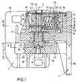
- a hinge door holder consists of a first hinge part 2 and a second hinge part 4.
- the two hinge parts 2, 4 are pivotably connected to one another about an axis of rotation 8 by means of a hinge pin 6.
- a locking device 10 is integrated, which defines various relative rotational positions.
- the latching device 10 consists on the one hand of at least one kinematically connected to the first hinge part 2 and spring-loaded in a direction of rotation 8 spring-loaded locking element 12 and on the other hand from a kinematically connected to the second hinge part 4, substantially circular sector-shaped and with respect to their radius of curvature to the axis of rotation 8 coaxial
- the first hinge part 2 consists of a substantially plate-shaped mounting portion 18, with which the first hinge part 2 can be fastened to a particular vertical mounting surface, as well as from a cantilever-like projecting support portion 20 which is connected via the hinge pin 6 with the second hinge part 4.
- the hinge pin 6 extends from the support portion 20 of the first hinge part 2 only in one direction, preferably vertically upwards.
- the second hinge part 4 is rotatably mounted on the hinge pin 6.
- the hinge pin 6 a particular cylindrical bearing portion 22 which extends through a pivot bearing opening 23 of the second hinge part 4.
- a sliding bushing 24 is disposed within the pivot bearing opening 23.
- end portion of the hinge pin 6 is torque-connected to the locking element 12. This will be explained in more detail below.
- the hinge pin 6 thus transmits forces or torques, so that it acts not only as an axis but as a shaft.
- the hinge pin 6 is releasably connected to the first hinge part 2 or with its support portion 20 via connecting means 26, so that the hinge parts 2 and 4 by releasing these connecting means 26 while maintaining the connection between the hinge pin 6 and the second hinge part 4 and the latching means associated with the second hinge part 4 separable, ie are aushlindbar.
- the connecting means 26 are formed such that the hinge pin 6 within the maximum possible pivoting range (about 70 ° to 80 °) of the hinge parts 2, 4 in only a specific relative position to the first hinge part 2 with this torque can be connected ("Fehlwinkel" ⁇ Türschwenkwinkel).
- the hinge pin 6 sits with a preferably tapered end 28 and play self-centering and secured against rotation in a correspondingly adapted receptacle 30 of the support portion 20 of the first hinge part 2.
- the end 28 of the hinge pin 6 has a deviating from the circular cross-section to ensure the rotationally fixed connection.
- it is a substantially conical configuration of the end 28 with a circular base cross-section and with a cross-sectional widening formed by a radial rib 32.
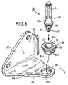
- the rib 32 engages without clearance in a correspondingly shaped recess 33 (see FIG. 8) within the receptacle 30.
- the end 28 of the hinge pin 6 may also have, for example, a polygonal cross-section or a circular base cross-section with at least one, e.g. formed by a secant-like area cross-sectional reduction.
- the connecting means 26 have a screw 34 passing through a hole opening 36 of the support portion 20 of the first hinge part 2 into an axial threaded bore 38 of the end 28 in the receptacle 30 recessed seated hinge pin 6 engages.
- a very short axial stroke H sufficient to separate the parts after the screw 34 has been removed.
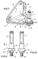
- Fig. 1 is additionally illustrated that in the case of an alternative embodiment (see Fig. 7 to 10), wherein the hinge pin 6, the hole opening 36 entirely engages with a threaded shaft 39 and is bolted to a nut, not shown, a larger stroke H. 'Is required to remove the hinge pin of the first hinge part 2 can.
- the latching device 10 is housed within a housing 40 integrally formed with the second hinge portion 4.
- the hinge pin 6 engages through a to the support portion 20 of the first hinge part 2 approximately parallel, the rotary guide opening 23 preferably with the sliding bush 24 having wall 42 into the housing 40 a.
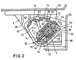
- the stationary track 16 for this purpose and, on the other hand, a guide adjusting element 46 leading to the latching element 12, which is connected in a torque-locking manner to a connecting section 44 of the hinge pin 6, are arranged.
- a guide adjusting element 46 leading to the latching element 12 which is connected in a torque-locking manner to a connecting section 44 of the hinge pin 6, are arranged.
- For the torque-locking connection of the connecting portion 44 has a deviating from the circular cross-section, in the example shown a polygonal, square cross section (see Fig.
- the housing 40 On its side facing away from the wall 42, the upper side, the housing 40 has an opening which serves for mounting the functional parts of the latching device 10 and preferably by means of a cover element 48 can be closed.
- the locking element 12 is arranged in a direction perpendicular to the axis of rotation 8 or radial direction slidably in a guide receptacle 50 of the guide member 46 and is acted upon by a spring element 52, in particular a helical compression spring, radially from the inside in the direction of the outer race 16 with spring force F.
- the locking element 12 is formed as a roller, roller or the like rotating rolling elements and rotatably mounted about an axis 54 in a receiving part 56 about an axis of rotation 8 parallel to the axis of rotation 8 axis.
- the receiving member 56 is in turn arranged according to the direction of action piston-like displaced in the guide member 46. For this purpose, reference is made in particular to FIG. 2.
- the track 16 is formed by a releasably and thus replaceable held in the housing 40 insert part 60.
- the locking points 14 are formed in particular as locking recesses 62 with adapted to the peripheral contour of the locking element 12 recess contour.
- the locking element 12 engages during the relative movement of the hinge parts 2, 4 in each case a detent recess 62 a.
- the position of the locking recesses 62 is in this case chosen in particular such that a fully open opening position of the vehicle door and preferably in addition an approximately half-open intermediate position (so-called garage position) are defined.
- the latching device 10 defined in a door-Schlleß ein kinematic upstream end portion of the relative movement of a pulling path for automatically closing the vehicle door.
- the track 16 - see again especially Fig. 2 - in their door-closed position upstream end portion of a Ziehwegabites 64 which extends from a certain inner radius of the track 16 obliquely outward to a larger radius. Due to this oblique course of the track 16 over the Ziehwegabites 64 away is due to the spring force F via the locking element 12 causes an automatic rotation of the associated with the door hinge part to the door closed position.
- the previous explanations apply to a "minimum version" of the hinge door holder according to the invention, wherein in principle a locking element 12 is sufficient. Depending on the application, however, it may be advantageous to provide a plurality of axially adjacent or superposed and parallel guided locking elements 12 to increase the locking and holding forces. In the illustrated embodiments specifically two parallel locking elements 12 are provided.
- the measures for guiding and Federkraftbeaufschlagung apply to each of the plurality of locking elements 12.
- the locking elements 12 associated raceways 16 can - as shown - be formed by a single, common insert 60. However, it can also be provided separate insert parts.
- each insert 60 is suitably supported by a positive connection in the housing 40, wherein the positive connection is formed so that a rigid, stationary support, in particular in the direction of movement of the locking elements is achieved.
- the positive connection can be axial groove guides 64 for axial insertion and removal of the insert 60, as shown (see in particular Fig. 2 and Fig. 3), for example, a dovetail guide, alternatively, for example, to T-slot guides.
- the interchangeability of the track 16 and the insert 60 allows easy and quick adaptation to various requirements.
- the hinge door holder can be designed for different locking positions and / or locking forces.
- a simple and quick maintenance is given.
- the raceway 16 and the locking element 12 are also advantageous to produce the raceway 16 and the locking element 12 in the region of its peripheral surface made of different materials, on the one hand of metal with a defined roughened surface structure and on the other hand of such an elastically yielding material that between the locking element 12 and the raceway 16 by means of elastic deformation of the resilient material, a surface contact with frictional engagement is achieved.
- a surface contact with frictional engagement is achieved.
- the latching element 12 is made of metal and has the defined roughened, in particular knurled surface structure, while the track 16, preferably the entire insert part 60, of the elastically yielding material, in particular a plastic having a hardness in the range of 72 to 80 Shore D, exists.
- the German Utility Model 296 11 819 in full scale.
- the spring force F acting on the latching element 12 is influenced over the movement range by means of a control device 70 such that the spring force F increases in the area of the latching points 14 or latching depressions 62 and / or the spring force F is reduced between the latching points or latching depressions 62 ,
- a reinforced detent can be achieved, and between the locking points can be ensured by reducing the spring force a slight movement with little wear.
- the control device 70 has at least one support element 72 for the respective spring element 52.
- This support member 72 consists of a plate-like part on which the spring element 52 is supported, as well as from a radially in the spring element 52 opposite direction through the guide member 46 and by the hinge pin 6 extending control pin 74.
- the control pin 74 acts with its free, the spring element 52 opposite end with control cam 76 to increase or reduce the spring force F together. Since the support element 72 is movably guided in spring-effective direction, a displacement of the spring support is achieved in cooperation with the control cam 76 during the relative movement.
- the control cams 76 are preferably located diametrically opposite the latching points.
- control pin 74 of the support element 72 should consist of a relatively hard, wear-resistant material or form a "good friction partner" for the control pin 74 of the support element 72 with respect to their material.
- the housing 40 is made of aluminum or the like of relatively “soft” material, so should the control cam 76 of harder inserts z. B. be formed of steel.
- the control cam 76 could also be integrally molded into the housing 40, if the material pairing with the control pin 74 permits this with respect to the friction behavior.
- both hinge parts 2 and 4 are in each case designed as a one-piece molded part, in particular made of light metal die casting (aluminum die casting) or as a pressed part or forged part. Should a light metal die casting not meet the required strength values, special methods such as vacuum die casting or vacuum casting or tixotropic casting are preferred. By this casting method, a more homogeneous structure is achieved, which can be compensated by heat treatment. This achieves a maximum yield strength with a high elongation at break.
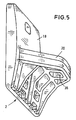
- FIGS. 3 to 5 it is clear that can be realized by the design as one-piece moldings relatively complicated space shapes with relatively little effort. Such complicated shapes would not be produced by forging, for example.
- the parts may also be made of plastic, for which purpose technically highly stressable, in particular fiber-reinforced plastics are suitable.
- hinge parts 2, 4 in each case in multiple parts, in particular detachably connected individual parts.
- the housing 40 - possibly together with the cover member 48 - a vice versa form cup-shaped housing part, which is then connected to the wall 42 and the mounting portion 18.
- the first hinge part 2 is provided for attachment to a fixed vehicle frame part (e.g., pillar) while the second hinge part 4 is to be fixed to the pivoting vehicle door.
- a fixed vehicle frame part e.g., pillar
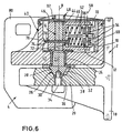
- a "kinematic inverted" embodiment is illustrated in which the first hinge part 2 of the vehicle door and the second hinge part 4 are associated with the fixed vehicle part.
- FIGS. 7 to 10 as an alternative to FIG. 5, a variant of embodiment of the first hinge part 2 is illustrated, which consists of sheet steel as a stamped sheet molding.
- a sleeve member 84 is expediently provided, which is inserted with a substantially cylindrical insert portion 84a in a hole opening 86 of the support portion 20 until it with a flange Edge 84b rests on the surface of the support portion 20.
- the insert section 84a has a secant-flattened region 84c (FIG. 8) and the hole opening 86 has a corresponding circular opening cross-section with a secant-like edge region 86a.
- the bushing element 84 is additionally connected in a materially bonded manner to the support section 20 of the first hinge part 2, in particular welded.
- the bushing element 84 in this case has the receptacle 30 with the radial recess 33 for the end 28 of the hinge pin 6.
- the end 28 sits in the manner of a self-locking cone or wedge connection in the receptacle 30 (wedge angle in the range of about 7 ° to a maximum of 14 °). This preferably also applies to the embodiments according to FIGS. 1 to 6.
- the sheet metal hinge part 2 may be fixed by certain means known per se, e.g. bead-like bends 88 and / or bent stiffening webs 90, be stiffened.
- the hinge pin 6 is also supported in its fixed connection with the first hinge part 2 axially opposite, upper end portion via an abutment 92 against lateral play movements relative to the second hinge part 4.
- This counter-bearing 92 is indicated only schematically in FIGS. 1 and 6; it is a rotatable guide in the housing 40, optionally in the region of the cover element 48.
Landscapes
- Engineering & Computer Science (AREA)
- Mechanical Engineering (AREA)
- Hinges (AREA)
- Hinge Accessories (AREA)
- Body Structure For Vehicles (AREA)
Claims (24)
- Support de porte à charnière, en particulier pour une porte de véhicule, comprenant deux parties de charnière (2, 4) reliées de façon mobile au moyen d'un gond à charnière (6) de façon à pouvoir pivoter autour d'un axe de rotation (8), entre lesquelles est intégré un dispositif d'encliquetage (10) définissant une position de rotation relative différente, le dispositif d'encliquetage (10) comprenant d'une part au moins un élément d'encliquetage (12) relié de façon cinématique à la première partie de charnière (2) et sollicité par ressort dans un sens d'action perpendiculaire à l'axe de rotation (8) et d'autre part une glissière (16) reliée de façon cinématique à la seconde partie de charnière (4), en supplément en forme de secteur circulaire et disposée sur le même axe en ce qui concerne son rayon de courbure par rapport à l'axe de rotation (8), présentant au moins un point d'encliquetage (14) coopérant avec l'élément d'encliquetage (12), le gond à charnière (6) étant relié de façon amovible à la première partie de charnière (2) par des moyens d'assemblage (26), de sorte que les parties de charnière (2, 4) peuvent être séparées par le détachement des moyens d'assemblage (26) en conservant l'assemblage entre le gond à charnière (6) et la seconde partie de charnière (4) et le dispositif d'encliquetage (10) attribué à cette dernière,
caractérisé en ce que le dispositif d'encliquetage (10) est logé à l'intérieur d'un boîtier (40) relié d'une seule pièce à la seconde partie de charnière (4), et en ce que le gond à charnière (6) est guidé de façon mobile en rotation dans le boîtier (40) au moyen d'un palier-support (92) dans sa zone d'extrémité supérieure, faisant face axialement à l'assemblage fixe avec la première partie de charnière (2) et faisant suite à la zone de l'élément d'encliquetage (12) et est soutenue ainsi radialement contre des mouvements de jeu latéraux par rapport à la seconde partie de charnière (4). - Support de porte à charnière selon la revendication 1,
caractérisé en ce que les moyens d'assemblage (26) sont reliés de telle sorte que le gond à charnière (6) peut être relié à l'intérieur de la zone de déplacement de pivotement maximal des parties de charnière (2, 4) dans une seule position relative définie par rapport à la première partie de charnière (2) par couple avec celle-ci. - Support de porte à charnière selon la revendication 1 ou 2,
caractérisé en ce que les moyens d'assemblage (26) présentent une vis (34), qui s'engage à travers une ouverture de trou (36) de la première partie de charnière (2) dans un alésage fileté (38) axial du gond à charnière (6). - Support de porte à charnière selon la revendication 1 ou 2,
caractérisé en ce que les moyens d'assemblage (26) se composent d'une tige filetée (39), côté extrémité, guidée à travers une ouverture de trou (36) de la première partie de charnière (2) et vissée avec un écrou de vissage, du gond à charnière (6). - Support de porte à charnière selon l'une quelconque des revendications 1 à 4,
caractérisé en ce que le gond à charnière (6) repose par une extrémité (28) se rétrécissant de préférence, à autocentrage et bloqué vis-à-vis d'une rotation dans un logement (30) adapté en conséquence de la première partie de charnière (2). - Support de porte à charnière selon la revendication 5,
caractérisé en ce que l'extrémité (28) du gond à charnière (6) présente une section divergente de la forme circulaire, en particulier une section polygonale ou une section de base circulaire avec au moins une extension de section formée par exemple par une nervure (32) radiale ou avec au moins une réduction de section formée par exemple par une zone par exemple de type sécante. - Support de porte à charnière selon la revendication 5 ou 6,
caractérisé en ce que le gond à charnière (6) repose par son extrémité (28) au moyen d'une liaison conique autobloquante dans le logement (30). - Support de porte à charnière selon l'une quelconque des revendications 1 à 7,
caractérisé en ce que la glissière (16) fixe par rapport au boîtier et une partie de guidage (46) guidant l'élément d'encliquetage (12) et reliée par couple au gond à charnière (6) sont disposées à l'intérieur du boîtier (40). - Support de porte à charnière selon l'une quelconque des revendications 1 à 8,
caractérisé en ce que le gond à charnière (6) est guidé de façon rotative avec une partie de palier (22) dans la seconde partie de charnière (4). - Support de porte à charnière selon la revendication 8 ou 9,
caractérisé en ce que l'élément d'encliquetage (12) est disposé dans un logement de guidage (50) de la partie de guidage (46) de façon coulissante dans une direction radiale par rapport à l'axe de rotation (8) et est sollicité par un élément de ressort (52) en direction de la glissière (16) avec une force de ressort (F). - Support de porte à charnière selon l'une quelconque des revendications 8 à 10,
caractérisé en ce que l'élément d'encliquetage (12) est conçu comme un galet et est logé au moyen d'un axe (54) dans une partie de logement (56) disposée à la façon d'un piston dans la partie de guidage (46) de façon à pouvoir tourner autour d'un axe de rotation (58) parallèle à l'axe de rotation de charnière (8). - Support de porte à charnière selon l'une quelconque des revendications 8 à 11,
caractérisé en ce que la glissière (16) est formée une partie d'insertion (60) maintenue de façon amovible dans le boîtier (40), les points d'encliquetage (14) étant conçus en particulier comme des cavités d'encliquetage (62) avec le contour adapté à l'élément d'encliquetage (12). - Support de porte à charnière selon l'une quelconque des revendications 1 à 12,
caractérisé en ce que la glissière (16) et l'élément d'encliquetage (12) sont à base de différents matériaux dans la zone de sa surface périphérique, et ce d'une part en métal avec une structure de surface rendue rugueuse de façon définie et d'autre part dans un matériau élastiquement souple de telle sorte qu'un contact d'appui plat avec adhérence soit obtenu entre l'élément d'encliquetage (12) et la glissière (16) par déformation élastique du matériau souple. - Support de porte à charnière selon la revendication 13,
caractérisé en ce que l'élément d'encliquetage (12) est à base de métal et présente la structure de surface rendue rugueuse de façon définie, en particulier une structure de surface moletée, alors que la glissière (16) est à base du matériau élastiquement souple, en particulier un matériau synthétique avec une dureté à peu près de l'ordre de 72 à 80 Shore-D. - Support de porte à charnière selon l'une quelconque des revendications 1 à 14,
caractérisé en ce que le dispositif d'encliquetage (10) présente au moins deux éléments d'encliquetage (12) voisins axialement et guidés en parallèle. - Support de porte à charnière selon l'une quelconque des revendications 1 à 15,
caractérisé en ce que la force de ressort (F) sollicitant l'élément d'encliquetage (12) est influencée au moyen d'un dispositif de commande (70) au-delà de la zone de déplacement, et ce en particulier de telle sorte qu'un encliquetage forcé est obtenu dans la zone des points d'encliquetage (14). - Support de porte à charnière selon l'une quelconque des revendications 1 à 16,
caractérisé en ce que l'élément de ressort (52) sollicitant l'élément d'encliquetage (12) est soutenu sur un autre côté au moyen d'un élément de soutien (72) disposé dans la partie de guidage (46) mobile dans le sens d'effet du ressort, l'élément de soutien (72) coopérant sur son côté opposé à l'élément de ressort (52) avec des cames de commande (76) pour augmenter ou réduire la force de ressort (F). - Support de porte à charnière selon l'une quelconque des revendications 1 à 17,
caractérisé en ce que le dispositif d'encliquetage (10) est réalisé dans une zone d'extrémité de son déplacement relatif, qui est placé en amont d'une position extrême correspondant à une position fermée d'une porte correspondante, de telle sorte que, à partir d'une position définie et sur une course de traction, la position extrême pour fermer la porte est atteinte automatiquement. - Support de porte à charnière selon la revendication 18,
caractérisé en ce que la glissière (16) du dispositif d'encliquetage (10) présente dans sa zone placée en avant de la position extrême une partie de course de traction (64) qui est agencée à partir d'un rayon intérieur en biais vers l'extérieur jusqu'à un rayon assez grand. - Support de porte à charnière selon l'une quelconque des revendications 1 à 19,
caractérisé en ce que la première et/ou la seconde partie de charnière (2, 4) est/sont conçue(s) comme des parties moulées d'une seule pièce en plastique ou en métal, en particulier à partir d'un moulage sous pression de métal léger. - Support de porte à charnière selon l'une quelconque des revendications 1 à 20,
caractérisé en ce qu'au moins la première partie de charnière (2) est formée comme une partie moulée pliée à base de tôle de métal, un élément de douille (84) étant fixé par couple de préférence pour la liaison avec le gond à charnière (6) et étant fixé en particulier par adhésion de matière dans la partie de charnière (2). - Support de porte à charnière selon l'une quelconque des revendications 1 à 21,
caractérisé en ce que la première partie de charnière (2) peut être attribuée à une partie de cadre de véhicule fixe et la seconde partie de charnière (4) à une porte de véhicule mobile en pivotement. - Support de porte à charnière selon l'une quelconque des revendications 1 à 21,
caractérisé en ce que la première partie de charnière (2) peut être attribuée à une porte de véhicule mobile en pivotement et la seconde partie de charnière (4) à une partie de cadre de véhicule fixe. - Support de porte à charnière selon l'une quelconque des revendications 1 à 23,
caractérisé en ce qu'une butée finale délimitant l'ouverture de la porte est formée entre les deux parties de charnière (2, 4).
Applications Claiming Priority (2)
| Application Number | Priority Date | Filing Date | Title |
|---|---|---|---|
| DE29713031U DE29713031U1 (de) | 1997-07-23 | 1997-07-23 | Scharniertürhalter für Fahrzeugtüren |
| DE29713031U | 1997-07-23 |
Publications (4)
| Publication Number | Publication Date |
|---|---|
| EP0893565A2 EP0893565A2 (fr) | 1999-01-27 |
| EP0893565A3 EP0893565A3 (fr) | 1999-03-10 |
| EP0893565B1 EP0893565B1 (fr) | 2002-10-30 |
| EP0893565B2 true EP0893565B2 (fr) | 2006-02-15 |
Family
ID=8043523
Family Applications (1)
| Application Number | Title | Priority Date | Filing Date |
|---|---|---|---|
| EP98113349A Expired - Lifetime EP0893565B2 (fr) | 1997-07-23 | 1998-07-17 | Charnière à arrêt de porte pour portes de véhicules |
Country Status (5)
| Country | Link |
|---|---|
| US (1) | US6073308A (fr) |
| EP (1) | EP0893565B2 (fr) |
| DE (2) | DE29713031U1 (fr) |
| ES (1) | ES2184179T5 (fr) |
| PT (1) | PT893565E (fr) |
Families Citing this family (31)
| Publication number | Priority date | Publication date | Assignee | Title |
|---|---|---|---|---|
| DE19817739A1 (de) * | 1998-04-21 | 1999-11-04 | Scharwaechter Ed Gmbh | In ein Scharnier integrierte Kraftwagentürbremse mit Öffnungsendanschlag |
| DE19817699A1 (de) * | 1998-04-22 | 1999-11-04 | Scharwaechter Ed Gmbh | Kraftwagentürscharnier mit integrierter Brems- und Haltefunktion |
| DE19915718C2 (de) * | 1999-04-08 | 2002-07-11 | Ise Ind Gmbh | Türscharnier für Kraftfahrzeuge |
| DE19922985A1 (de) * | 1999-05-19 | 2000-01-13 | Giok Djien Go | Rettungssystem eines Zuges oder Fahrzeuges |
| DE19953077B4 (de) * | 1999-11-04 | 2004-02-12 | Edscha Ag | Türscharnier mit integriertem Türfeststeller |
| FR2811007B1 (fr) | 2000-06-29 | 2003-05-16 | Aries Ind Mecanismes Et Decoup | Charniere avec arret de porte integre |
| WO2002023000A1 (fr) * | 2000-09-13 | 2002-03-21 | Friedr. Fingscheidt Gmbh | Dispositif d'arret de porte a charniere, destine en particulier a des portes de vehicule |
| KR20020040354A (ko) * | 2000-11-24 | 2002-05-30 | 이계안 | 자동차의 도어체커 겸용 도어힌지 |
| DE10116242B4 (de) * | 2001-03-31 | 2013-08-01 | Volkswagen Ag | Anordnung zur Befestigung eines schwenkbaren Anbauteils |
| DE10296314D2 (de) * | 2002-01-16 | 2005-03-03 | Fingscheidt Gmbh Friedr | Scharniertürhalter für Kraftfahrzeuge |
| KR20030092228A (ko) * | 2002-05-29 | 2003-12-06 | 현대자동차주식회사 | 도어체커 일체형 도어힌지장치 |
| KR100528591B1 (ko) * | 2003-09-16 | 2005-11-15 | 현대자동차주식회사 | 도어힌지 체결용 너트 및 브라켓의 결합구조 |
| DE102004012006B3 (de) * | 2004-03-10 | 2005-06-30 | Ise Innomotive Systems Europe Gmbh | Türscharnier für Kraftfahrzeuge |
| DE102004049552B8 (de) * | 2004-10-12 | 2010-08-05 | Edscha Ag | Scharnier für eine Fahrzeugtür |
| DE102004057614B3 (de) * | 2004-11-29 | 2006-06-14 | Ise Innomotive Systems Europe Gmbh | Rastscharnier mit federbelastetem Rastkörper |
| US7373693B2 (en) * | 2004-12-01 | 2008-05-20 | Illinois Tool Works Inc. | Hinge assembly |
| DE102005017929A1 (de) * | 2005-04-18 | 2006-10-19 | Friedr. Fingscheidt Gmbh | Verwendung eines Leichtbaustahls |
| DE102006002346A1 (de) * | 2006-01-18 | 2007-07-19 | Bayerische Motoren Werke Ag | Teilbare Türbremse |
| DE102006011455A1 (de) * | 2006-03-13 | 2007-09-20 | Stabilus Gmbh | Gelenkanordnung, insbesondere Mehrgelenkscharnier |
| US8117716B2 (en) * | 2006-06-05 | 2012-02-21 | Shiroki Kogyo Co., Ltd. | One-way valve and door check apparatus |
| CN101737420B (zh) * | 2008-11-21 | 2012-03-07 | 鸿富锦精密工业(深圳)有限公司 | 铰链结构及采用该铰链结构的电子装置 |
| JP5606724B2 (ja) * | 2009-11-24 | 2014-10-15 | 理研化機工業株式会社 | 車両用チェッカ付きドアヒンジ装置 |
| DE102013010325A1 (de) | 2013-06-19 | 2014-12-24 | Daimler Ag | Verstärkungselement für eine Kraftfahrzeugtür, Kraftfahrzeugtür und Verfahren zur Herstellung eines Verstärkungselements |
| US9458653B2 (en) * | 2014-11-21 | 2016-10-04 | Nissan North America, Inc. | Check link structure |
| EP3330463A1 (fr) * | 2016-12-05 | 2018-06-06 | Innomotive Systems Hainichen GmbH | Charnière de porte |
| GB2577068B (en) | 2018-09-12 | 2020-09-09 | Ford Global Tech Llc | A motor vehicle having a door check mechanism |
| BR112022025764B1 (pt) * | 2020-06-17 | 2023-12-05 | Multimatic Inc | Articulação de dobradiça de remoção automotiva |
| JP7055288B1 (ja) * | 2021-08-27 | 2022-04-18 | 株式会社ニイテック | 車両用チェッカ付きドアヒンジ、および該ドアヒンジを備えた車両 |
| DE102021125785B3 (de) | 2021-10-05 | 2022-05-25 | Bayerische Motoren Werke Aktiengesellschaft | Gewindebolzen und Scharnieranordnung mit derartigem Gewindebolzen |
| CN114922519B (zh) * | 2022-06-28 | 2024-03-29 | 浙江吉利控股集团有限公司 | 铰链组件及车辆 |
| DE112024004613T5 (de) * | 2023-11-02 | 2026-08-20 | Multimatic Inc. | Schaniersystem zur ausrichtung von fahrzeugtüren |
Family Cites Families (22)
| Publication number | Priority date | Publication date | Assignee | Title |
|---|---|---|---|---|
| DE14076C (de) | J. BERNOULLI & CO. in Basel | Mechanische Beschläge für Thüren, Läden und Fenster | ||
| US2992451A (en) * | 1958-06-23 | 1961-07-18 | Lisle W Menzimer | Door holding devices |
| IT1016871B (it) * | 1974-08-23 | 1977-06-20 | Saseb Ag | Cerniera per porte di autoveicoli atta a trattenere la porta sia in posizione parzialmente aperta sia in posizione totalmente aperta |
| DE7722449U1 (de) | 1977-07-18 | 1979-01-11 | Nowoczin, Wolfgang, 2000 Wedel | Eckverbinder fuer tueren |
| DE3137134A1 (de) * | 1980-12-01 | 1982-07-01 | Friedr. Fingscheidt Gmbh, 5620 Velbert | "tuerscharnier mit integriertem tuerhalter" |
| DE3137112A1 (de) | 1981-09-18 | 1983-04-07 | Ed. Scharwächter GmbH + Co KG, 5630 Remscheid | Aushaengbares tuerscharnier |
| DE3405083A1 (de) * | 1983-10-10 | 1985-08-14 | Ed. Scharwächter GmbH & Co KG, 5630 Remscheid | Aushaengbares fluegelscharnier |
| DE3406984C2 (de) | 1984-02-13 | 1993-11-18 | Scharwaechter Gmbh Co Kg | Aushängbares Flügelscharnier |
| FR2610662B1 (fr) * | 1986-12-27 | 1990-07-06 | Scharwaechter Gmbh Co Kg | Charniere de porte decrochable |
| US4765025A (en) * | 1986-12-29 | 1988-08-23 | Ford Motor Company | Vehicle door mounting assembly for effecting vertical removability |
| IT215091Z2 (it) * | 1988-12-16 | 1990-07-30 | Memo Spa | Cerniera con asse di articolazione orientabile |
| WO1991019876A1 (fr) * | 1989-04-12 | 1991-12-26 | Mgi Coutier (S.A.) | Charniere a crans de retenue pour une porte, notamment d'un vehicule automobile |
| US5067201A (en) * | 1989-11-06 | 1991-11-26 | Atwood Industries, Inc. | Door on-door off vehicle hinge with anti-slap hold-open mechanism |
| FR2670530A1 (fr) * | 1990-12-12 | 1992-06-19 | Coutier Moulage Gen Ind | Charniere a mecanisme de retenue integre, et sous-ensemble de cette charniere. |
| FR2703394B1 (fr) | 1993-03-29 | 1995-06-30 | Coutier Moulage Gen Ind | Mecanisme d'arret pour une charniere de porte, notamment dans un vehicule automobile. |
| DE9314325U1 (de) | 1993-09-22 | 1995-01-26 | Julius & August Erbslöh GmbH & Co, 42553 Velbert | Flügelscharnier |
| FR2722233B1 (fr) * | 1994-07-07 | 1996-09-27 | Coutier Moulage Gen Ind | 1charniere de porte a cran de retenu2vehicule automobile |
| CZ331796A3 (en) * | 1996-01-03 | 1997-07-16 | Scharwaechter Gmbh Co Kg | Door hinge of motor vehicle with braking and holding-down functions |
| DE19619473A1 (de) | 1996-05-14 | 1997-11-20 | Scharwaechter Gmbh Co Kg | Mit einem aushängbaren Türscharnier baulich vereinigter Türfeststeller |
| DE29611580U1 (de) * | 1996-07-03 | 1996-12-19 | Ed. Scharwächter GmbH + Co KG, 42855 Remscheid | Kraftwagentürfeststeller |
| DE29614386U1 (de) * | 1996-08-20 | 1996-10-24 | Ed. Scharwächter GmbH + Co KG, 42855 Remscheid | Mit einem aushängbaren Türscharnier baulich vereinigter Türfeststeller |
| DE29621575U1 (de) | 1996-12-12 | 1997-03-06 | Ed. Scharwächter GmbH + Co KG, 42855 Remscheid | Brems- bzw. Halteelemente für Kraftwagentürfeststeller |
-
1997
- 1997-07-23 DE DE29713031U patent/DE29713031U1/de not_active Expired - Lifetime
-
1998
- 1998-07-17 PT PT98113349T patent/PT893565E/pt unknown
- 1998-07-17 DE DE59806096T patent/DE59806096D1/de not_active Expired - Lifetime
- 1998-07-17 EP EP98113349A patent/EP0893565B2/fr not_active Expired - Lifetime
- 1998-07-17 ES ES98113349T patent/ES2184179T5/es not_active Expired - Lifetime
- 1998-07-23 US US09/121,251 patent/US6073308A/en not_active Expired - Fee Related
Also Published As
| Publication number | Publication date |
|---|---|
| DE29713031U1 (de) | 1998-12-03 |
| EP0893565B1 (fr) | 2002-10-30 |
| US6073308A (en) | 2000-06-13 |
| DE59806096D1 (de) | 2002-12-05 |
| ES2184179T5 (es) | 2006-08-01 |
| ES2184179T3 (es) | 2003-04-01 |
| EP0893565A3 (fr) | 1999-03-10 |
| PT893565E (pt) | 2003-03-31 |
| EP0893565A2 (fr) | 1999-01-27 |
Similar Documents
| Publication | Publication Date | Title |
|---|---|---|
| EP0893565B1 (fr) | Charnière à arrêt de porte pour portes de véhicules | |
| EP3020902B1 (fr) | Chariot à bobines pour la réception d'une porte coulissante dotée d'un dispositif anti-levage | |
| EP3880920B1 (fr) | Ensemble destiné à guider une porte coulissante | |
| EP1317598A1 (fr) | Dispositif d'arret de porte a charniere, destine en particulier a des portes de vehicule | |
| EP3029238B1 (fr) | Ferrure d'angle dotée d'une plage de serrage réglable | |
| DE10118301B4 (de) | Kraftwagentürscharnier | |
| DE4119610A1 (de) | Spindelantrieb fuer eine verstelleinrichtung fuer fahrzeugsitze | |
| EP3621484B1 (fr) | Dispositif de retenue pour façade de tiroir | |
| DE2340762A1 (de) | Scharnier | |
| EP3293331B1 (fr) | Charnière pour véhicule automobile | |
| EP1070188B1 (fr) | Element d'arret pour portieres de vehicule automobile | |
| DE3418138C2 (de) | Bandzapfenbüchse | |
| DE102013100922B4 (de) | Laufteil zum Führen eines Möbelteils in einer Führungsrichtung über eine Führungsschiene und Möbelbeschlag | |
| EP0777025A1 (fr) | Charnière pour porte de véhicule avec fonction de retenue et de freinage | |
| EP4067611A2 (fr) | Charnière de porte et porte | |
| DE102009037357B4 (de) | Verschlussanordnung für ein bewegliches Fahrzeugteil | |
| EP0728892B1 (fr) | Palier pour un battant | |
| EP0837206A2 (fr) | Charnière de porte pour le support pivotant d'un vantail de porte sur un cadre de porte | |
| WO2007147473A1 (fr) | Bande pour portes, fenêtres ou équivalent | |
| DE9017985U1 (de) | Bandzapfenbüchse | |
| EP2021566A1 (fr) | Charnière à fixation améliorée de l'axe d'articulation | |
| EP1776511A1 (fr) | Dispositif d'arret de portieres de vehicules | |
| DE29802682U1 (de) | Scharniertürhalter für Fahrzeugtüren | |
| DE3109553A1 (de) | Haltevorrichtung fuer eine schwenktuer | |
| DE20015850U1 (de) | Scharniertürhalter für Fahrzeuge |
Legal Events
| Date | Code | Title | Description |
|---|---|---|---|
| PUAI | Public reference made under article 153(3) epc to a published international application that has entered the european phase |
Free format text: ORIGINAL CODE: 0009012 |
|
| PUAL | Search report despatched |
Free format text: ORIGINAL CODE: 0009013 |
|
| AK | Designated contracting states |
Kind code of ref document: A2 Designated state(s): DE ES FR GB IT PT SE |
|
| AX | Request for extension of the european patent |
Free format text: AL;LT;LV;MK;RO;SI |
|
| AK | Designated contracting states |
Kind code of ref document: A3 Designated state(s): AT BE CH CY DE DK ES FI FR GB GR IE IT LI LU MC NL PT SE |
|
| AX | Request for extension of the european patent |
Free format text: AL;LT;LV;MK;RO;SI |
|
| 17P | Request for examination filed |
Effective date: 19990908 |
|
| AKX | Designation fees paid |
Free format text: DE ES FR GB IT SE |
|
| RBV | Designated contracting states (corrected) |
Designated state(s): DE ES FR GB IT PT SE |
|
| 17Q | First examination report despatched |
Effective date: 20010123 |
|
| GRAG | Despatch of communication of intention to grant |
Free format text: ORIGINAL CODE: EPIDOS AGRA |
|
| GRAG | Despatch of communication of intention to grant |
Free format text: ORIGINAL CODE: EPIDOS AGRA |
|
| GRAH | Despatch of communication of intention to grant a patent |
Free format text: ORIGINAL CODE: EPIDOS IGRA |
|
| GRAH | Despatch of communication of intention to grant a patent |
Free format text: ORIGINAL CODE: EPIDOS IGRA |
|
| GRAA | (expected) grant |
Free format text: ORIGINAL CODE: 0009210 |
|
| AK | Designated contracting states |
Kind code of ref document: B1 Designated state(s): DE ES FR GB IT PT SE |
|
| REG | Reference to a national code |
Ref country code: GB Ref legal event code: FG4D Free format text: NOT ENGLISH |
|
| REF | Corresponds to: |
Ref document number: 59806096 Country of ref document: DE Date of ref document: 20021205 |
|
| GBT | Gb: translation of ep patent filed (gb section 77(6)(a)/1977) |
Effective date: 20021205 |
|
| ET | Fr: translation filed | ||
| REG | Reference to a national code |
Ref country code: PT Ref legal event code: SC4A Free format text: AVAILABILITY OF NATIONAL TRANSLATION Effective date: 20030121 |
|
| REG | Reference to a national code |
Ref country code: ES Ref legal event code: FG2A Ref document number: 2184179 Country of ref document: ES Kind code of ref document: T3 |
|
| PLBQ | Unpublished change to opponent data |
Free format text: ORIGINAL CODE: EPIDOS OPPO |
|
| PLBI | Opposition filed |
Free format text: ORIGINAL CODE: 0009260 |
|
| PLAX | Notice of opposition and request to file observation + time limit sent |
Free format text: ORIGINAL CODE: EPIDOSNOBS2 |
|
| 26 | Opposition filed |
Opponent name: EDSCHA AG Effective date: 20030730 |
|
| PLAX | Notice of opposition and request to file observation + time limit sent |
Free format text: ORIGINAL CODE: EPIDOSNOBS2 |
|
| PLBB | Reply of patent proprietor to notice(s) of opposition received |
Free format text: ORIGINAL CODE: EPIDOSNOBS3 |
|
| PUAH | Patent maintained in amended form |
Free format text: ORIGINAL CODE: 0009272 |
|
| STAA | Information on the status of an ep patent application or granted ep patent |
Free format text: STATUS: PATENT MAINTAINED AS AMENDED |
|
| 27A | Patent maintained in amended form |
Effective date: 20060215 |
|
| AK | Designated contracting states |
Kind code of ref document: B2 Designated state(s): DE ES FR GB IT PT SE |
|
| REG | Reference to a national code |
Ref country code: SE Ref legal event code: RPEO |
|
| GBTA | Gb: translation of amended ep patent filed (gb section 77(6)(b)/1977) | ||
| PGFP | Annual fee paid to national office [announced via postgrant information from national office to epo] |
Ref country code: PT Payment date: 20060714 Year of fee payment: 9 |
|
| PGFP | Annual fee paid to national office [announced via postgrant information from national office to epo] |
Ref country code: GB Payment date: 20060719 Year of fee payment: 9 |
|
| PGFP | Annual fee paid to national office [announced via postgrant information from national office to epo] |
Ref country code: ES Payment date: 20060724 Year of fee payment: 9 |
|
| PGFP | Annual fee paid to national office [announced via postgrant information from national office to epo] |
Ref country code: IT Payment date: 20060731 Year of fee payment: 9 |
|
| REG | Reference to a national code |
Ref country code: ES Ref legal event code: DC2A Date of ref document: 20060427 Kind code of ref document: T5 |
|
| REG | Reference to a national code |
Ref country code: FR Ref legal event code: RN |
|
| REG | Reference to a national code |
Ref country code: FR Ref legal event code: FC |
|
| EN | Fr: translation not filed | ||
| ET3 | Fr: translation filed ** decision concerning opposition | ||
| EN | Fr: translation not filed | ||
| PGFP | Annual fee paid to national office [announced via postgrant information from national office to epo] |
Ref country code: SE Payment date: 20060726 Year of fee payment: 9 |
|
| REG | Reference to a national code |
Ref country code: PT Ref legal event code: MM4A Free format text: LAPSE DUE TO NON-PAYMENT OF FEES Effective date: 20080117 |
|
| EUG | Se: european patent has lapsed | ||
| GBPC | Gb: european patent ceased through non-payment of renewal fee |
Effective date: 20070717 |
|
| PG25 | Lapsed in a contracting state [announced via postgrant information from national office to epo] |
Ref country code: SE Free format text: LAPSE BECAUSE OF NON-PAYMENT OF DUE FEES Effective date: 20070718 |
|
| PG25 | Lapsed in a contracting state [announced via postgrant information from national office to epo] |
Ref country code: PT Free format text: LAPSE BECAUSE OF NON-PAYMENT OF DUE FEES Effective date: 20080117 Ref country code: GB Free format text: LAPSE BECAUSE OF NON-PAYMENT OF DUE FEES Effective date: 20070717 |
|
| REG | Reference to a national code |
Ref country code: ES Ref legal event code: FD2A Effective date: 20070718 |
|
| PG25 | Lapsed in a contracting state [announced via postgrant information from national office to epo] |
Ref country code: ES Free format text: LAPSE BECAUSE OF NON-PAYMENT OF DUE FEES Effective date: 20070718 |
|
| PGFP | Annual fee paid to national office [announced via postgrant information from national office to epo] |
Ref country code: FR Payment date: 20070731 Year of fee payment: 10 |
|
| PG25 | Lapsed in a contracting state [announced via postgrant information from national office to epo] |
Ref country code: IT Free format text: LAPSE BECAUSE OF NON-PAYMENT OF DUE FEES Effective date: 20070717 |
|
| PG25 | Lapsed in a contracting state [announced via postgrant information from national office to epo] |
Ref country code: FR Free format text: LAPSE BECAUSE OF NON-PAYMENT OF DUE FEES Effective date: 20080730 |
|
| REG | Reference to a national code |
Ref country code: FR Ref legal event code: EERR Free format text: CORRECTION DE BOPI 07/14 - 3.2. Ref country code: FR Ref legal event code: EERR Free format text: CORRECTION DE BOPI 07/01 - 3.2. |
|
| REG | Reference to a national code |
Ref country code: FR Ref legal event code: ST Effective date: 20111223 |
|
| PGFP | Annual fee paid to national office [announced via postgrant information from national office to epo] |
Ref country code: DE Payment date: 20150928 Year of fee payment: 18 |
|
| REG | Reference to a national code |
Ref country code: DE Ref legal event code: R119 Ref document number: 59806096 Country of ref document: DE |
|
| PG25 | Lapsed in a contracting state [announced via postgrant information from national office to epo] |
Ref country code: DE Free format text: LAPSE BECAUSE OF NON-PAYMENT OF DUE FEES Effective date: 20170201 |