EP0894636B1 - Drucker mit drehbarer Infrarotschnittstelle mit Abschirmung gegen elektrostatische Aufladung. - Google Patents
Drucker mit drehbarer Infrarotschnittstelle mit Abschirmung gegen elektrostatische Aufladung. Download PDFInfo
- Publication number
- EP0894636B1 EP0894636B1 EP98114215A EP98114215A EP0894636B1 EP 0894636 B1 EP0894636 B1 EP 0894636B1 EP 98114215 A EP98114215 A EP 98114215A EP 98114215 A EP98114215 A EP 98114215A EP 0894636 B1 EP0894636 B1 EP 0894636B1
- Authority
- EP
- European Patent Office
- Prior art keywords
- infrared ray
- printer
- ray communication
- case member
- communication unit
- Prior art date
- Legal status (The legal status is an assumption and is not a legal conclusion. Google has not performed a legal analysis and makes no representation as to the accuracy of the status listed.)
- Expired - Lifetime
Links
Images



Classifications
-
- B—PERFORMING OPERATIONS; TRANSPORTING
- B41—PRINTING; LINING MACHINES; TYPEWRITERS; STAMPS
- B41J—TYPEWRITERS; SELECTIVE PRINTING MECHANISMS, i.e. MECHANISMS PRINTING OTHERWISE THAN FROM A FORME; CORRECTION OF TYPOGRAPHICAL ERRORS
- B41J3/00—Typewriters or selective printing or marking mechanisms characterised by the purpose for which they are constructed
- B41J3/36—Typewriters or selective printing or marking mechanisms characterised by the purpose for which they are constructed for portability, i.e. hand-held printers or laptop printers
- B41J3/37—Foldable typewriters
-
- G—PHYSICS
- G06—COMPUTING OR CALCULATING; COUNTING
- G06K—GRAPHICAL DATA READING; PRESENTATION OF DATA; RECORD CARRIERS; HANDLING RECORD CARRIERS
- G06K15/00—Arrangements for producing a permanent visual presentation of the output data, e.g. computer output printers
-
- G—PHYSICS
- G06—COMPUTING OR CALCULATING; COUNTING
- G06K—GRAPHICAL DATA READING; PRESENTATION OF DATA; RECORD CARRIERS; HANDLING RECORD CARRIERS
- G06K2215/00—Arrangements for producing a permanent visual presentation of the output data
- G06K2215/0002—Handling the output data
- G06K2215/0005—Accepting output data; Preparing data for the controlling system
Definitions
- This invention relates to a printer according to the preamble of claim 1, using infrared rays for a data communication medium to effect data communication with an external data processing apparatus such as a computer.
- Apparatuses which effect data communication between data processing apparatuses such as computers in a near distance space such as the interior of a room with not a cable but infrared rays as a communication medium are disclosed in JP-A- 59-000235, JP-A-1-312621 and JP-A-2-186847. If such optical communication is utilized, the bus lines between the data processing apparatuses can be curtailed or omitted and the degree of freedom of the spatial disposition of the data processing apparatuses will be improved and a reduction in the cost of facilities will be achieved.
- infrared ray communication the data communication utilizing infrared rays as described above (hereinafter referred to as the "infrared ray communication")
- the light emission and light reception of infrared rays have directionality and therefore, unless the angles of disposition of the transmission side data processing apparatus and the reception side data processing apparatus are within an appropriate range, there has been the problem that reliability of data exchange cannot be secured.
- a printer body contains an infrared ray communication apparatus therein is disclosed in JP-A-5-290195, etc. but generally, the sizes of a computer, an information apparatus, etc. which provide the data transmission side and the position of an infrared ray emitting portion are various. Therefore, when infrared ray communication is to be effected with these apparatuses, it is necessary to appropriately adjust the angles of disposition of the both apparatuses, and this has led to the problem that the installation and operation of the apparatuses become cumbersome.
- a generic printer for effecting recording on a recording medium by recording means is known from DE-A-19619732.
- This printer includes conveying means for conveying the recording medium, an infrared ray communication unit containing in a case member an infrared ray communication element for effecting data communication with an external data processing apparatus with an infrared ray as a communication medium; and supporting means for rotatably supporting the infrared ray communication unit on the printer so as to be protrudable from the surface of the outer case of the printer.
- the case member has a first case member formed with an opening portion in one end surface thereof and containing the infrared ray communication element therein, and a second case member formed of a material intercepting the light of a wavelength in a visible light range and transmitting therethrough the light of a wavelength used in infrared ray communication and covering the opening portion of the first case member.
- the infrared ray communication element faces the second case member and is contained in the first case member.
- JP-A-8-251106 discloses a further printer having a rotatable infrared ray communication unit protruding from the casing.
- a printer in which an area capable of effecting infrared ray communication is secured widely by a simple construction and which is saved in space and is provided with an infrared ray communicating function of high reliability.
- An infrared ray communication unit portion is made protrudable from that side of the outer surface of the printer which is along the direction of conveyance of a recording medium and data communication is not hampered by a recording medium set in the printer or a recording medium discharged and the infrared ray communication unit portion does not hamper the recording medium set in the printer or the recording medium discharged.
- Fig. 1 is a perspective view schematically showing the construction of an embodiment of the printer of the present invention (for the details, see Japanese Laid-Open Patent Application No. 8-058107).
- the printer 1 of the present embodiment is comprised of recording means 2 comprising a recording head 3 carried on a carriage 4, the recording means 2 being contained in an outer case 7 comprised of an upper case 5 and a lower case 6.
- a top cover 8 covering the upper case 5 is provided on the inner part of the upper case 5 so as to be openable and closable relative to the upper case 5, and further a feeding opening portion 5a for feeding a recording medium 9 into the printer 1 is provided in the upper surface of the inner part of the upper case 5.
- the top cover 8 provides a tray for setting the recording medium in the printer 1.
- the carriage 4 When the recording medium 9 is conveyed downwardly of the carriage 4 from the feeding opening portion 5a by conveying means (not shown) provided in the printer 1, the carriage 4 is scanned in a direction intersecting with the direction of conveyance of the recording medium 9 (e.g. a direction orthogonal to said direction of conveyance) on the basis of a signal from a control circuit (not shown). Ink is then discharged from a plurality of discharge ports (not shown) provided in the recording head held on the carriage 4, for example, an ink jet recording head cartridge 3 comprising an ink jet recording portion and an ink tank portion made integral with each other, to the recording paper 9 which is a recording medium, and image information is recorded on the recording medium 9.
- a heat generating resistance member as means for generating heat energy for discharging ink from the ink discharge ports is disposed in the aforementioned ink jet recording portion.
- the recording medium 9 on which the image information has been recorded is further conveyed by the conveying means, and is discharged out of the printer 1 through a discharge opening portion 7a formed in the front face of the outer case 7.
- the printer 1 of the present embodiment has an infrared ray communication unit 10 for effecting data communication with a data processing apparatus (not shown) by the use of an infrared ray contained in the right side relative to the direction of conveyance of the recording medium 9.
- a portion of the case member of the infrared ray communication unit 10 forms a portion of the surface of the outer case 7 of the printer 1.
- the infrared ray communication unit 10 is provided on that side of the printer 1 which is along the direction of conveyance of the recording medium 9 and therefore does not hamper a set recording medium 9 or a discharged recording medium 9.
- the infrared ray communication unit 10 will hereinafter be described.
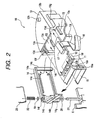
- Fig. 2 is an exploded perspective view of the infrared ray communication unit of the printer shown in Fig. 1.
- the infrared ray communication unit 10 has a printed base plate 12 on which an infrared ray communication element 11 is mounted, a first case member 13 and a second case member 14 constituting a case in which the printed base plate 12 is contained, and a noise shield 15 for preventing the entry of noise into the infrared ray communication unit 10.
- the printed base plate 12 will first be described.
- the infrared ray communication element 11 is mounted on the printed base plate 12 and in addition, a driving circuit for driving the infrared ray communication element 11, a power source circuit and a protection circuit (all being not shown) are formed on the printed base plate 12. Further, a connector 17 to which a flexible cable 16 is connected is mounted on the printed base plate 12.
- the infrared ray communication element 11 has an infrared ray emitting portion 11a for transmitting data from the printer 1 to the data processing apparatus, and an infrared ray receiving portion 11b for receiving the data transmitted from the data processing apparatus.
- the infrared ray communication element 11 has its side, bottom surface and back (a surface opposite to the surface on which the infrared ray emitting portion 11a, etc. are formed) covered by a shield plate 18 formed by a metallic plate being bent.
- the shield plate 18 is fixed to the printed base plate 12 while being electrically connected to the ground line of the printed base plate 12. Thereby, any noise generated from the power source line of the printed base plate 12 is intercepted by the shield plate 18 and therefore, malfunctioning of the infrared ray communication element 11 is prevented.
- the first case member 13 will now be described.
- the first case member 13 is formed into a substantially sectoral shape and has planar side portions 13a, 13b and a curved side portion 13c. However, the planar side portion 13a is formed with an opening portion.
- the inner wall of the first case member 13 is formed with a groove portion 13d for guiding the side edge of the printed base plate 12 when the printed base plate 12 is to be contained from the opening portion into the first case member 13 and effecting the positioning of the printed base plate 12.
- a flexible cable guide 13e having a smooth curved surface is formed on the right edge of the opening portion as viewed in Fig. 2 so that a flexible cable 16 can be drawn out of the case without being bent.
- a hook portion 13f engaged with the hook groove 14a of the second case member 14 which will be described later is formed on the left edge of the opening portion as viewed in Fig.
- a pawl portion engaging portion 13g engaged by the pawl portion 14b of the second case member 14 is formed on the planar side portion 13b. Further, a projection-like stopper 13h is provided on the upper surface portion of the first case member 13, and a first finger engaging portion 13i is provided on the lower surface portion of the first case member 13.
- the second case member 14 will now be described.
- the second case member 14 is a planar member covering the opening portion of the first case member 13, and as previously described, has the hook groove 14a engaged by the hook portion 13f of the first hook member 13, and the pawl portion 14b engaged by the pawl portion engaging portion 13g of the first case member 13. Further, a second finger engaging portion 14c is formed on the surface of a portion formed with the hook groove 14a. Also, the second case member 14 is provided with a shaft aperture portion 14d supported by a pivot shaft 21 fixed to the lower case 6. The shaft aperture portion 14d is provided so as to be located near the flexible cable guide 13b of the first case member 13 when the first case member 13 and the second case member 14 are united together. Further, the second case member 14 is provided with a rib 14e for holding the noise shield 15. Also, a first click projection 14i is provided on the lower surface of the second finger engaging portion 14c.
- the noise shield 15 is formed by a metallic plate being bent.
- the noise shield 15 is formed with a beam portion 15a by a portion of the side thereof being hollowed out, and a contact 15b provided by being bent into a mountain-shape is provided on the tip end of the beam portion 15a.
- the infrared ray communication unit 10 is constructed by combining the first case member 13 and the second case member 14 together in a state in which the printed base plate 12 is fixedly contained in the groove portion 13a of the first case member 13 and the noise shield 15 is sandwiched between the ribs 14e of the second case member 14.
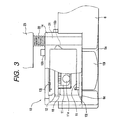
- Fig. 3 is a front view showing the infrared ray communication unit shown in Fig. 1 with the second case member in front thereof. However, a portion of the second case member 14 and the upper case 5 of the printer 1 are omitted in the showing.
- the second case member 14 is disposed in front of the light receiving portion 11a and light emitting portion 11b (see Fig. 2) of the infrared ray communication element 11.
- the material of the second case member 14 is a material substantially intercepting the light of a wavelength in the visible light range and exhibiting high transmittance for the light of a wavelength used in infrared ray communication.
- toned polycarbonate resin of which the transmittance for the light in the visible light range (wavelength of about 380 nm - 780 nm) is 1 % or less and the transmittance for the light in the infrared ray range (wavelength of about 850 nm - 900 nm) is 87 % or greater.
- the second case member 14 functions as an infrared ray transmitting window which is an infrared ray filter, and the entry of a noise component included in extraneous light such as a fluorescent lamp and becoming the factor for the malfunctioning of the infrared ray communication element 11 into the second case member 14 is prevented.
- the internal part such as the infrared ray communication element 11 becomes almost invisible from the outside of the infrared ray communication unit 10 and therefore does not spoil the appearances of the printer 1.
- the second case member 14 functions as a filter which intercepts any extraneous light noise and therefore, the curtailment of the number of parts and the curtailment of the number of assembling steps can be achieved and moreover, the accuracy and reliability of infrared ray communication can be heightened.
- the noise shield 15 is sandwiched between the ribs 14e (see Fig. 2) of the second case member 14 and does not contact with the printed base plate 12, the shield plate 18 and the infrared ray communication element 11. Also, the noise shield 15 bears against a plurality of ribs 13j formed on the inner surface of the first case member 13 and has its movement in the direction of opening (the direction of arrow) of the first case member 13 regulated. Thereby, the noise shield 15 is fixed so that the upper and lower flat portions thereof may be along the joint 10a (see Fig. 4) of the first case member 13 and the second case member 14.
- the lower case 6 is provided with a recess 6a for containing therein a first finger engaging portion 13i provided on the first case member 13 of the infrared ray communication unit 10.
- the second case member 14 is provided with the aforedescribed shaft aperture portion 14d.
- a washer receptor 14f in which a washer 19 is installed is formed on the upper portion of the shaft aperture portion 14d
- a rubber ring receptor 14g in which a rubber ring 20 is installed is formed on the lower portion of the shaft aperture portion 14d.
- the rubber ring 20 is formed of a rubber material having elasticity and therefore, by being compressed between the rubber ring receptor 14g and the pivot shaft 21, it is given moderate friction when the infrared ray communication unit 10 is rotated.
- the construction of the infrared ray communication unit 10 is simplified and therefore the assembling property is improved.
- the washer 19 is inserted into the pivot shaft 21 protruding from the upper portion of the shaft aperture portion 14d and the washer 19 is installed in the washer receptor 14f and further, a metallic spring 22 is inserted into the pivot shaft 21 while being forced thereinto, and the lower end portion of the spring 22 is rammed against the washer 19.
- the washer 19 is formed of a material such as resin of relatively high sliding property.
- the upper end portion of the spring 22 bears against a metallic chassis 23 provided in the printer 1 and grounded. Thereby, the noise shield installed in the infrared ray communication unit 10 is grounded through the pivot shaft 21 and the spring 22.
- the lower case 6 is provided with a second click projection 6c.
- the second click projection 6c and the aforementioned first click projection 14i come into engagement with each other, and a moderate click feeling is given to an operator.
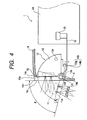
- Fig. 4 is a partly broken-away cross-sectional top plan view showing the interior of the printer shown in Fig. 1.
- a flexible cable 16 connected to the printed base plate 12 (see Fig. 2) is drawn out of the case along a flexible cable guide 13b formed on the first case member 13, and is connected to a connector 25 mounted on a main base plate 24 fixed in the printer 1. That is, the transmission of an electrical signal between the main base plate 24 and the infrared ray communication unit 10 is effected by the flexible cable 16.
- the infrared ray communication unit 10 is provided with the first finger engaging portion 13f formed on the first case member 13, and the second finger engaging portion 14c formed on the second case member 14, as previously described.
- a finger is inserted into a recess 6a (see Fig. 3) formed in the lower case 6 of the printer 1 and a finger is engaged with the finger engaging portion 13f, and the infrared ray communication unit 10 is drawn out while the engagement between the aforementioned first click projection 14i and the second click projection 6c (see Fig. 3) is released, whereby the infrared ray communication unit 10 is rotated about the pivot shaft 21.
- the infrared ray communication unit 10 can be easily brought from the state in which it is contained in the printer 1 into a state in which it is protruded outwardly of the printer with a moderate click feeling.
- the infrared ray communication unit 10 having the infrared ray communication element 11 and the case member 14 as an infrared ray transmitting window and rotatably supported on the printer 1 assumes a state in which the second case member 14 is protruded from the surface of the outer case 7 of the printer 1.
- a finger can be engaged with the second finger engaging portion 14c from a recess 6b formed in the back of the lower case 6, whereby as described above, the infrared ray communication unit 10 can be easily brought from the state in which it is contained in the printer 1 into a state in which it is protruded outwardly of the printer 1.
- a finger can be engaged with the second finger engaging portion 14c from the back of the printer 1 to thereby rotate the infrared ray communication unit 10 and draw the infrared ray communication unit 10 out of the printer 1. Also, by a finger being engaged with the first finger engaging portion 13f from the recess 6a formed in the lower case 6, and rotating the infrared ray communication unit 10, the infrared ray communication unit 10 can be drawn out of the printer 1.
- an exterior type battery 30 or the like is mounted on the back of the printer 1, whereby a finger becomes unengageable with the second finger engaging portion 14c, a finger can be engaged with the first finger engaging portion 13f from the recess 6a formed in the lower case 6 to thereby rotate the infrared ray communication unit 10 and drawn out the infrared ray communication unit 10 from the surface of the outer case 7 of the printer 1.
- the edge portion 14h of the second case member 14 which becomes the remotest end portion from the printer 1 when the infrared ray communication unit 10 is rotated is formed roundly. Further, the maximum angle of rotation ⁇ of the infrared ray communication unit 10 is set to less than 90°.
- the maximum angle of rotation ⁇ of the infrared ray communication unit 10 is set to less than 90°, whereby the reliability of the structural strength of the infrared ray communication unit 10 is improved as compared with a case where the infrared ray communication unit 10 opens to 90° or greater.
- the angle of rotation for which there is obtained the degree of freedom of the disposition relation between the data processing apparatus which is the object of infrared ray communication and the printer is about 30° or greater, and on the other hand, the angle of rotation for which it is difficult for the infrared ray communication unit 10 to be destroyed or otherwise seriously damaged as during the fall of the printer 1 is about 85° or less, and from this fact, it is desirable that the maximum angle of rotation ⁇ of the infrared ray communication unit 10 be 30° ⁇ ⁇ ⁇ 85°.
- dots-and-dash line indicates the infrared ray communication unit as it has been drawn out of the printer.
- the maximum angle of rotation ⁇ of the infrared ray communication unit 10 from the side of the printer 1 which is shown in Fig. 4 is regulated by the stopper 13h formed on the upper surface portion of the first case member 13 bearing against the inner wall of the upper case 5 (see Fig. 1) of the printer 1.
- the infrared ray communication element 11 has the specification of displaying desired light receiving performance or light emitting performance within the angle range of ⁇ from the front direction of the light receiving portion 11a and the light emitting portion 11b.
- the flexible cable guide 13e which is the draw-out port of the flexible cable 16 is also rotated therewith.
- the flexible cable guide 13e is formed at the right edge of the opening portion of the first case member 13 near the pivot shaft 21. Therefore, the amount of displacement of the flexible cable 16 resulting from the rotation is smaller than when the flexible cable guide is provided at other place. Accordingly, the movement of the flexible cable 16 resulting from the rotation of the infrared ray communication unit 10 is minimized and therefore, it is difficult for the bending, tension, etc. of the cable to occur, and the occurrence of an accident such as the breakage of the signal line of the cable or the contact thereof with other part can be prevented.
- a case member restraining structure comprised of the pawl portion 14b of the second case member 14 and the pawl portion engaging portion 13g of the first case member 13 is not exposed outside the printer 1 even when the infrared ray communication unit 10 is maximally rotated. Therefore, there is not the possibility that the second case member 14 suddenly touches a case member restraining portion 10b and thereby comes off the first case member 13, and the infrared ray communication element 11 contained in the infrared ray communication unit 10 can be protected more reliably.
- the second finger engaging portion 14c is provided on the surface of a portion formed with a hook groove 14a (see Fig. 2) engaged by the hook portion 13f of the first case member 13, whereby when a finger is engaged with the second finger engaging portion 14c to thereby rotate the infrared ray communication unit 10, it never happens that the second case member 14 comes off the first case member 13.
- the discharge of static electricity may happen, for example, from a finger tip or the like, depending on the environment or the like.
- the infrared ray communication element 11 is relatively weak to the electrical shock by static electricity and therefore, static electricity must be made to escape quickly to the chassis portion or the like of the printer 1 which is sufficiently earthed.
- the case parts constituting the infrared ray communication unit 10 are only two parts, i.e., the first and second case members 13 and 14, and therefore, the gap in the case which provides the entry path of static electricity into the infrared ray communication unit 10 is limited to the joint portion 10a between these two parts. Further, of this joint portion 10a, a joint portion 10a comprising the hook portion 13f of the first case member 13 and the hook groove 14a of the second case member 14 shown in Fig. 2 is of turned-back structure and therefore, it is difficult for static electricity to enter this joint portion.
- static electricity enters through joint portions 10a formed on the upper surface portion and lower surface portion of the infrared ray communication unit 10, but the static electricity which has entered flows from the noise shield 15 fixed near those joint portions 10a to a metallic chassis 23 through the pivot shaft 21 and the spring 22 and therefore, it does not happen that the static electricity falls onto the printed base plate 12 including the infrared ray communication element 11, and the malfunctioning and destruction of the printer 1 can be prevented. That is, static electricity eliminating means for eliminating the static electricity entering the interior of the infrared ray communication unit 10 through the joint portion 10a which is the gap between the first case member 13 and the second case member 14 to the outside of the infrared ray communication unit 10 is constituted by the noise shield 15, the pivot shaft 21 and the spring 22.
- Figs. 7 to 11 describe an example of the arrangement of the printer 1 provided with the infrared ray communication unit 10 and the data processing apparatus such as a computer.
- Fig. 7 is a top plan view showing the disposition relation between a data processing apparatus having an infrared ray communication portion fixed to the right side thereof and the printer.
- the printer 1 is disposed on the right side of the data processing apparatus 26, whereby the infrared ray communication portion 26a of the data processing apparatus 26 and the infrared ray communication unit 10 of the printer 1 are opposed to each other and infrared ray communication between the two is effected well. Further, near the front face of the printer 1, there is no apparatus or the like which is an obstacle and therefore, there is no hindrance to the operability of the data processing apparatus 26 and the discharging operation for the recording medium 9 (see Fig. 1) after the recording of image information.
- Fig. 8 is a top plan view showing the disposition relation between a data processing apparatus having the infrared ray communication portion fixed to the back thereof and the printer.
- the printer 1 is disposed on the back of the data processing apparatus 27, whereby the infrared ray communication portion 27a of the data processing apparatus 27 and the infrared ray communication unit 10 of the printer 1 are opposed to each other.
- infrared ray communication between the two is effected well and there is no hindrance to the operability of the data processing apparatus 27 and the discharging operation for the recording medium 9 (see Fig. 1).
- Fig. 9 is a top plan view showing the disposition relation between a data processing apparatus having an infrared ray communication portion fixed to the left side thereof and the printer.
- the printer 1 With the infrared ray communication unit 10 drawn out of the printer 1 by an angle ⁇ , the printer 1 with its left side turned to the front is disposed leftwardly rearwardly of the data processing apparatus 28, whereby the infrared ray communication portion 28a of the data processing apparatus 28 and the infrared ray communication unit 10 of the printer 1 are opposed to each other at an angle whereat desired communication performance is displayed.
- infrared ray communication between the two is effected well and there is no hindrance to the operability of the data processing apparatus 28 and the discharging operation for the recording medium 9 (see Fig. 1).
- the infrared ray communication unit 10 As shown in Fig. 10, with the infrared ray communication unit 10 provided on the left side of the printer 1 remaining contained in the printer 1, the infrared ray communication unit 10 and the infrared ray communication portion 28a are opposed to each other and the printer 1 is disposed on the right side of the data processing apparatus 28, whereby also the infrared ray communication between the two is effected well.
- the space for the recording medium 9 discharged from the printer 1 is taken into consideration, a wider space becomes necessary in the direction of depth of an installation bed on which the printer 1, etc. are installed and therefore, it is evident that the disposition shown in Fig. 9 is superior.
- Fig. 11 is a top plan view showing the disposition relation between a data processing apparatus having an infrared ray communication portion fixed to the left side thereof and the printer.
- the data processing apparatus shown in Fig. 11 is a small portable information terminal or the like, and has an infrared ray communication portion 29a provided on the back thereof.
- the data processing apparatus 29 is portable and therefore, infrared ray communication with the printer 1 can be effected from various directions.
- the infrared ray communication unit 10 of the printer 1 is drawn out in conformity with the direction of communication, whereby infrared ray communication is effected well and therefore, the printer 1 can be operated without the disposed state of the printer 1 being minded.
- the infrared ray communication unit 10 can be arbitrarily changed over between the state in which it is contained in the printer 1 and the state in which it has been drawn out of the printer 1 and therefore, the area in which infrared ray communication is possible is widened, and the degree of freedom of the disposition with respect to the data processing apparatus can be improved.
- the printer as described above is a printer provided with an infrared ray communication unit portion, and the infrared ray communication unit portion is rotatably supported on the printer so as to be capable of being protruded from the outer case of the printer and therefore, the area of the printer which is capable of effecting infrared ray communication is widely secured and thus, the degree of freedom of the disposition relation between the printer and the data processing apparatus can be improved.
- the infrared ray communication unit portion is provided on that side of the printer which is along the direction of conveyance of the recording medium, whereby the infrared ray communication unit portion can be prevented from hindering a set recording medium or a discharged recording medium.
- the maximum angle of rotation of the infrared ray communication unit from the outer case of the printer is selected between 30° and 85°, whereby the degree of freedom of the disposition relation between the data processing apparatus and the printer can be obtained and it can be made difficult for the infrared ray communication unit portion to receive serious damage such as destruction as during the fall of the printer.
- the edge portion of the infrared ray communication unit which becomes the remotest end portion relative to the outer case of the printer when the infrared ray communication unit is protruded from the outer case of the printer is formed roundly whereby as during the fall of the printer, it becomes difficult for the edge portion of the infrared ray communication unit portion which becomes the remotest end portion from the printer to be caught by the surface of the fallen article, and the infrared ray communication unit portion can be contained more smoothly in the printer.
- the flexible cable connected to the printed base plate on which the infrared ray communication element is mounted and which is contained in the infrared ray communication unit portion is drawn out of the infrared ray communication unit portion from the vicinity of the supported portion of the infrared ray communication unit portion, it becomes difficult for the bending, tension, etc. of the cable to occur and the occurrence of accidents such as the breakage of the signal line of the cable and the contact thereof with other parts can be prevented.
- a finger engaging portion for drawing the infrared ray communication unit portion out of the printer is provided on the infrared ray communication unit portion, whereby the infrared ray communication unit portion can be easily protruded out of the printer.
- the case member of the infrared ray communication unit portion is comprised of a first case member formed with an opening portion and containing the infrared ray communication element therein, and a second case member formed of a material intercepting the light of a wavelength in the visible light range and transmitting therethrough the light of a wavelength used in infrared ray communication, and covering the opening portion of the first case member, whereby the second case member functions as an infrared ray filter and can prevent the entry of an external light noise component which makes the factor of the malfunctioning of the infrared ray communication element.
- the restraining portions of the first case member and the second case member are provided so as not to be exposed to the outside of the printer even if the infrared ray communication unit portion is rotated up to a maximum angle of rotation relative to the surface of the outer case, whereby there is not the possibility of the second case member suddenly coming off the first case member, and the infrared ray communication element in the infrared ray communication unit portion can be protected more reliably.
- a printer for effecting recording on a recording medium by recording means includes conveying means for conveying the recording medium, an infrared ray communication unit containing in a case member an infrared ray communication element for effecting data communication with an external data processing apparatus with an infrared ray as a communication medium, and supporting means for rotatably supporting the infrared ray communication unit on the printer so as to be protrudable from the surface of the outer case of the printer , wherein said case member has a first case member formed with an opening portion in one end surface thereof and containing said infrared ray communication element therein, and a second case member formed of a material intercepting the light of a wavelength in a visible light range and transmitting therethrough the light of a wavelength used in infrared ray communication and covering the opening portion of said first case member, and said infrared ray communication element faces said second case member and is contained in said first case member, wherein provision is made of static electricity eliminating means for eliminating static electricity entering from the gap between said first case
Landscapes
- Engineering & Computer Science (AREA)
- General Engineering & Computer Science (AREA)
- Physics & Mathematics (AREA)
- General Physics & Mathematics (AREA)
- Theoretical Computer Science (AREA)
- Accessory Devices And Overall Control Thereof (AREA)
- Optical Communication System (AREA)
Claims (14)
- Drucker (1) zum Bewirken eines Aufzeichnens auf ein Aufzeichnungsmedium mittels einer Aufzeichnungseinrichtung (2), umfassend
eine Fördereinrichtung zum Fördern des Aufzeichnungsmediums (9),
eine Infrarotschnittstele (10) mit einem Infrarotübertragungsteil (11) in einem Gehäuseteil (13, 14) zur Datenübertragung mit einer externen Datenübertragungsvorrichtung mit einer Infrarotstrahlung als Übertragungsmedium, und
eine Lagereinrichtung (21) zum drehbaren Lagern der Infrarotschnittstelle (10) an dem Drucker so, dass sie von der Fläche des äußeren Gehäuses des Druckers (1) herausschwenkbar ist, wobei das Gehäuseteil (13, 14) ein erstes Gehäuseteil (13) mit einem in seiner einen Endfläche ausgebildeten Öffnungsabschnitt, in dem das Infrarotübertragungsteil (11) angeordnet ist, und ein zweites Gehäuseteil (14) aus einem das Licht mit einer Wellenlänge im sichtbaren Lichtbereich abschirmenden Material zur Übertragung des Lichts mit einer zur Infrarotübertragung verwendeten Wellenlänge und zur Abdeckung des Öffnungsabschnitts des ersten Gehäuseteils (13) aufweist, und das Infrarotübertragungsteil (11) dem zweiten Gehäuseteil (14) zugewandt ist und in dem ersten Gehäuseteil (13) aufgenommen ist,
dadurch gekennzeichnet, dass
eine Einrichtung (15, 21) zur Aufhebung der statischen Elektrizität, die von einem Spalt zwischen dem ersten Gehäuseteil (13) und dem zweiten Gehäuseteil (14) in das Innere des Gehäuseteils (13, 14) von der Außenseite des Gehäuseteils (13, 14) eintritt, vorgesehen ist. - Drucker nach Anspruch 1, wobei die Infrarotschnittstelle (10) von der Oberflächenseite des äußeren Gehäuses längs der Förderrichtung des Aufzeichnungsmediums (9) herausschwenkbar gelagert ist.
- Drucker nach Anspruch 1, wobei der maximale Drehwinkel der Infrarotschnittstelle (10) relativ zur Fläche des äußeren Gehäuses weniger als 90° beträgt.
- Drucker nach Anspruch 1, wobei der maximale Drehwinkel der Infrarotschnittstelle (10) relativ zur Fläche des äußeren Gehäuses in einem Bereich von 30° bis 85° liegt.
- Drucker nach Anspruch 1, wobei der Randabschnitt (14h) der Infrarotschnittstelle, der relativ zur Oberfläche des äußeren Gehäuses am entferntesten angeordnet wird, wenn die Infratorschnittstelle (10) vom äußeren Gehäuse des Druckers (1) herausgeschwenkt wird, rund ausgebildet ist.
- Drucker nach Anspruch 1, wobei das Infrarotübertragungsteil auf einer gedruckten Grundplatte (12) befestigt und in dem Gehäuseteil (13, 14) mit der gedruckten Grundplatte (12) aufgenommen ist, ein flexibles Kabel (16) zum Bewirken der Datenübertragung mit der Hauptgrundplatte in dem Drucke (1) mit der gedruckten Grundplatte (12) verbunden ist und das flexible Kabel (16) durch die Nähe des Drehmittelpunktes der Infrarotschnittstelle (10) aus der Infrarotschnittstelle (10) herausgezogen wird.
- Drucker nach Anspruch 1, wobei die Infrarotschnittstelle (10) mit einem Fingereingriffsabschnitt (14c) versehen ist.
- Drucker nach Anspruch 1, wobei das erste Gehäuseteil (13) und das zweite Gehäuseteil (14) in einer Einheit eingespannt sind und der eingespannte Abschnitt des ersten Gehäuseteils (13) und des zweiten Gehäuseteils (14) so ausgebildet sind, dass er nicht zur Außenseite des Druckers (1) vorsteht, auch wenn die Infrarotschnittstelle (10) zum maximalen Drehwinkel relativ zur Oberfläche des äußeren Gehäuses gedreht wird.
- Drucker nach Anspruch 1, wobei das erste Gehäuseteil (13) und das zweite Gehäuseteil (14) so eingespannt sind, dass sich das zweite Gehäuseteil (14) nicht vom ersten Gehäuseteil (13) löst, wenn die Infrarotschnittstelle (10) mittels Verwendung des Fingereingriffsabschnitts (14c) gedreht wird.
- Drucker nach Anspruch 1, wobei ein gelagerter Abschnitt (14d) der Infrarotschnittstelle (10) relativ zum Drucker (1) an dem zweiten Gehäuseteil (14) vorgesehen ist.
- Drucker nach Anspruch 1, wobei die Einrichtung (15, 21) zur Aufhebung der statischen Elektrizität eine in der Nähe des Spalts befestigte Rauschabschirmung (15) und einen die Infrarotschnittstelle (10) drehbar am Drucker (1) lagernden Schwenkwellenabschnitt (21) umfasst und elektrisch mit einem metallischen Grundkörperabschnitt des Druckers (1) verbunden und mit der Rauschabschirmung (15) geerdet ist.
- Drucker nach Anspruch 1, wobei der Abschnitt des Gehäuseteils (13, 14) als ein Abschnitt der Oberfläche des äußeren Gehäuses ausgebildet ist.
- Drucker nach einem der Ansprüche 1 bis 12, wobei die Aufzeichnungseinrichtung (2) als ein Tintenstrahlaufzeichnungskopf ausgebildet ist.
- Drucker nach Anspruch 13, wobei der Tintenstrahlaufzeichnungskopf (2) mit einem Wärmeerzeugungsteil zur Erzeugung von Wärme zum Ausstoßen von Tinte versehen ist.
Applications Claiming Priority (3)
| Application Number | Priority Date | Filing Date | Title |
|---|---|---|---|
| JP20655197 | 1997-07-31 | ||
| JP20655197A JP3403014B2 (ja) | 1997-07-31 | 1997-07-31 | プリンタ |
| JP206551/97 | 1997-07-31 |
Publications (3)
| Publication Number | Publication Date |
|---|---|
| EP0894636A2 EP0894636A2 (de) | 1999-02-03 |
| EP0894636A3 EP0894636A3 (de) | 2004-11-03 |
| EP0894636B1 true EP0894636B1 (de) | 2007-04-25 |
Family
ID=16525268
Family Applications (1)
| Application Number | Title | Priority Date | Filing Date |
|---|---|---|---|
| EP98114215A Expired - Lifetime EP0894636B1 (de) | 1997-07-31 | 1998-07-29 | Drucker mit drehbarer Infrarotschnittstelle mit Abschirmung gegen elektrostatische Aufladung. |
Country Status (4)
| Country | Link |
|---|---|
| US (1) | US6507408B2 (de) |
| EP (1) | EP0894636B1 (de) |
| JP (1) | JP3403014B2 (de) |
| DE (1) | DE69837639T2 (de) |
Families Citing this family (7)
| Publication number | Priority date | Publication date | Assignee | Title |
|---|---|---|---|---|
| JP4018813B2 (ja) | 1998-07-03 | 2007-12-05 | 富士通株式会社 | 携帯電話機 |
| US6576903B2 (en) * | 2001-05-31 | 2003-06-10 | Hewlett-Packard Development Company, L.P. | Infrared detector with feedback |
| JP2003170640A (ja) * | 2001-12-07 | 2003-06-17 | Brother Ind Ltd | 印刷装置 |
| JP4387651B2 (ja) * | 2002-10-07 | 2009-12-16 | キヤノン株式会社 | 記録装置 |
| USD699726S1 (en) * | 2012-10-19 | 2014-02-18 | Brother Industries, Ltd. | Scanner |
| USD706269S1 (en) * | 2012-12-13 | 2014-06-03 | Hewlett-Packard Development Company, L.P. | Imaging device |
| JP6842341B2 (ja) * | 2017-03-30 | 2021-03-17 | 富士通コンポーネント株式会社 | 電子装置 |
Family Cites Families (16)
| Publication number | Priority date | Publication date | Assignee | Title |
|---|---|---|---|---|
| JPS59235A (ja) | 1982-06-25 | 1984-01-05 | Yokogawa Hokushin Electric Corp | 通信システム |
| US4856090A (en) * | 1984-05-22 | 1989-08-08 | Canon Kabushiki Kaisha | Light communication equipment |
| JPH01312621A (ja) | 1988-06-10 | 1989-12-18 | Matsushita Graphic Commun Syst Inc | データ処理装置 |
| JPH02186847A (ja) | 1988-11-14 | 1990-07-23 | Photonics Corp | 赤外線ネットワーク・トランシーバ装置 |
| WO1993009490A1 (en) * | 1991-11-04 | 1993-05-13 | Vpr Systems Ltd. | Lap-top computer for retrieving and displaying text and graphic information encoded on personal library cd-rom |
| JPH07123241B2 (ja) | 1991-12-10 | 1995-12-25 | スター精密株式会社 | 赤外線データ通信装置 |
| JPH05290195A (ja) | 1992-04-14 | 1993-11-05 | Tokyo Electric Co Ltd | プリンタ装置 |
| JP2801149B2 (ja) | 1994-08-24 | 1998-09-21 | キヤノン株式会社 | インクタンクおよびインクタンクホルダ |
| JP3707084B2 (ja) * | 1994-10-31 | 2005-10-19 | ソニー株式会社 | 表示装置及び表示方法 |
| JP2944451B2 (ja) * | 1995-03-10 | 1999-09-06 | 日本電気株式会社 | 赤外線通信機能付携帯型電子機器 |
| JPH08300773A (ja) * | 1995-05-15 | 1996-11-19 | Asahi Optical Co Ltd | 光データ通信装置およびプリンタ |
| JPH08300772A (ja) * | 1995-05-15 | 1996-11-19 | Asahi Optical Co Ltd | データ通信表示装置およびプリンタ |
| US5717567A (en) * | 1995-09-29 | 1998-02-10 | Toshiba America Information Systems | Folding rack system for mobile office |
| CA2166356C (en) * | 1995-12-29 | 2002-01-29 | Albert John Kerklaan | Universally directionally adjustable optical transmitter and receiver assembly |
| CA2166357C (en) * | 1995-12-29 | 2002-07-02 | Albert John Kerklaan | Infrared transceiver for an application interface card |
| US5880867A (en) * | 1996-03-29 | 1999-03-09 | Intermec Ip Corp. | Infrared backbone communication network having a radio frequency backup channel |
-
1997
- 1997-07-31 JP JP20655197A patent/JP3403014B2/ja not_active Expired - Fee Related
-
1998
- 1998-07-21 US US09/119,731 patent/US6507408B2/en not_active Expired - Fee Related
- 1998-07-29 DE DE69837639T patent/DE69837639T2/de not_active Expired - Lifetime
- 1998-07-29 EP EP98114215A patent/EP0894636B1/de not_active Expired - Lifetime
Non-Patent Citations (1)
| Title |
|---|
| None * |
Also Published As
| Publication number | Publication date |
|---|---|
| JPH1148576A (ja) | 1999-02-23 |
| EP0894636A3 (de) | 2004-11-03 |
| EP0894636A2 (de) | 1999-02-03 |
| DE69837639D1 (de) | 2007-06-06 |
| US20020041382A1 (en) | 2002-04-11 |
| DE69837639T2 (de) | 2007-12-27 |
| JP3403014B2 (ja) | 2003-05-06 |
| US6507408B2 (en) | 2003-01-14 |
Similar Documents
| Publication | Publication Date | Title |
|---|---|---|
| KR102944448B1 (ko) | 디스플레이 보호 구조를 포함하는 폴더블 전자 장치 | |
| US6166722A (en) | Portable electronic apparatus having pointing device | |
| US20040042159A1 (en) | Attachable/detachable keyboard apparatus of portable computer system | |
| JP4649133B2 (ja) | 電子機器 | |
| EP3355154B1 (de) | Elektronische vorrichtung | |
| US10897545B2 (en) | Display-and-operation device and image forming apparatus | |
| US6507408B2 (en) | Printer | |
| US20090002931A1 (en) | Display device and electronic apparatus | |
| US20120307475A1 (en) | Electronic Device | |
| EP1329979A1 (de) | Elektronische Vorrichtung und Verfahren um eine Antenne zu montieren | |
| US5530578A (en) | Optical communication unit | |
| US5812371A (en) | Orientation-adjustable infrared transceiver used in a notebook type computer | |
| US20060082958A1 (en) | Electronic equipment | |
| US6353531B1 (en) | Integrated visor for a notebook computer | |
| EP0606111B1 (de) | Erweiterungskartenschlitz | |
| US10326224B2 (en) | Portable printer | |
| US20190347909A1 (en) | Processing terminal | |
| EP1434410B1 (de) | Anschlussvorrichtung für Telefongerät und tragbares Telefongerät | |
| JP2022092264A (ja) | 車載装置 | |
| JP2000181574A (ja) | 保護カバー及び保護カバーを有する電子機器 | |
| JP4079697B2 (ja) | 情報処理装置及びプリント基板 | |
| US20050212829A1 (en) | Thermal printing head comprising a guide member for the print tape configured as protective cover for a flexible control printed circuit board | |
| GB2344940A (en) | Detachable protector members adapted to be mated with a portable terminal device | |
| KR19980015418A (ko) | 컴퓨터 | |
| CN220933352U (zh) | 保护件和处理盒套件 |
Legal Events
| Date | Code | Title | Description |
|---|---|---|---|
| PUAI | Public reference made under article 153(3) epc to a published international application that has entered the european phase |
Free format text: ORIGINAL CODE: 0009012 |
|
| AK | Designated contracting states |
Kind code of ref document: A2 Designated state(s): AT BE CH CY DE DK ES FI FR GB GR IE IT LI LU MC NL PT SE |
|
| AX | Request for extension of the european patent |
Free format text: AL;LT;LV;MK;RO;SI |
|
| PUAL | Search report despatched |
Free format text: ORIGINAL CODE: 0009013 |
|
| AK | Designated contracting states |
Kind code of ref document: A3 Designated state(s): AT BE CH CY DE DK ES FI FR GB GR IE IT LI LU MC NL PT SE |
|
| AX | Request for extension of the european patent |
Extension state: AL LT LV MK RO SI |
|
| RIC1 | Information provided on ipc code assigned before grant |
Ipc: 7H 04B 10/10 B Ipc: 7G 06F 3/12 B Ipc: 7B 41J 3/50 A |
|
| 17P | Request for examination filed |
Effective date: 20050316 |
|
| 17Q | First examination report despatched |
Effective date: 20050428 |
|
| AKX | Designation fees paid |
Designated state(s): DE ES FR GB IT NL |
|
| RTI1 | Title (correction) |
Free format text: PRINTER WITH ROTATABLE INFRARED COMMUNICATIONS INTERFACE WITH SHIELDING MEANS TO REDUCE NOISE INDUCED BY STATIC ELECTRICITY. |
|
| GRAP | Despatch of communication of intention to grant a patent |
Free format text: ORIGINAL CODE: EPIDOSNIGR1 |
|
| GRAS | Grant fee paid |
Free format text: ORIGINAL CODE: EPIDOSNIGR3 |
|
| GRAA | (expected) grant |
Free format text: ORIGINAL CODE: 0009210 |
|
| AK | Designated contracting states |
Kind code of ref document: B1 Designated state(s): DE ES FR GB IT NL |
|
| REG | Reference to a national code |
Ref country code: GB Ref legal event code: FG4D |
|
| REF | Corresponds to: |
Ref document number: 69837639 Country of ref document: DE Date of ref document: 20070606 Kind code of ref document: P |
|
| PG25 | Lapsed in a contracting state [announced via postgrant information from national office to epo] |
Ref country code: ES Free format text: LAPSE BECAUSE OF FAILURE TO SUBMIT A TRANSLATION OF THE DESCRIPTION OR TO PAY THE FEE WITHIN THE PRESCRIBED TIME-LIMIT Effective date: 20070805 |
|
| NLV1 | Nl: lapsed or annulled due to failure to fulfill the requirements of art. 29p and 29m of the patents act | ||
| EN | Fr: translation not filed | ||
| PG25 | Lapsed in a contracting state [announced via postgrant information from national office to epo] |
Ref country code: NL Free format text: LAPSE BECAUSE OF FAILURE TO SUBMIT A TRANSLATION OF THE DESCRIPTION OR TO PAY THE FEE WITHIN THE PRESCRIBED TIME-LIMIT Effective date: 20070425 |
|
| PLBE | No opposition filed within time limit |
Free format text: ORIGINAL CODE: 0009261 |
|
| STAA | Information on the status of an ep patent application or granted ep patent |
Free format text: STATUS: NO OPPOSITION FILED WITHIN TIME LIMIT |
|
| 26N | No opposition filed |
Effective date: 20080128 |
|
| PG25 | Lapsed in a contracting state [announced via postgrant information from national office to epo] |
Ref country code: IT Free format text: LAPSE BECAUSE OF FAILURE TO SUBMIT A TRANSLATION OF THE DESCRIPTION OR TO PAY THE FEE WITHIN THE PRESCRIBED TIME-LIMIT Effective date: 20070425 Ref country code: FR Free format text: LAPSE BECAUSE OF FAILURE TO SUBMIT A TRANSLATION OF THE DESCRIPTION OR TO PAY THE FEE WITHIN THE PRESCRIBED TIME-LIMIT Effective date: 20071221 |
|
| PG25 | Lapsed in a contracting state [announced via postgrant information from national office to epo] |
Ref country code: FR Free format text: LAPSE BECAUSE OF FAILURE TO SUBMIT A TRANSLATION OF THE DESCRIPTION OR TO PAY THE FEE WITHIN THE PRESCRIBED TIME-LIMIT Effective date: 20070425 |
|
| PGFP | Annual fee paid to national office [announced via postgrant information from national office to epo] |
Ref country code: DE Payment date: 20130731 Year of fee payment: 16 |
|
| PGFP | Annual fee paid to national office [announced via postgrant information from national office to epo] |
Ref country code: GB Payment date: 20130712 Year of fee payment: 16 |
|
| REG | Reference to a national code |
Ref country code: DE Ref legal event code: R119 Ref document number: 69837639 Country of ref document: DE |
|
| GBPC | Gb: european patent ceased through non-payment of renewal fee |
Effective date: 20140729 |
|
| PG25 | Lapsed in a contracting state [announced via postgrant information from national office to epo] |
Ref country code: DE Free format text: LAPSE BECAUSE OF NON-PAYMENT OF DUE FEES Effective date: 20150203 |
|
| REG | Reference to a national code |
Ref country code: DE Ref legal event code: R119 Ref document number: 69837639 Country of ref document: DE Effective date: 20150203 |
|
| PG25 | Lapsed in a contracting state [announced via postgrant information from national office to epo] |
Ref country code: GB Free format text: LAPSE BECAUSE OF NON-PAYMENT OF DUE FEES Effective date: 20140729 |