EP0897800A2 - Aufzeichnungsverfahren - Google Patents
Aufzeichnungsverfahren Download PDFInfo
- Publication number
- EP0897800A2 EP0897800A2 EP98306383A EP98306383A EP0897800A2 EP 0897800 A2 EP0897800 A2 EP 0897800A2 EP 98306383 A EP98306383 A EP 98306383A EP 98306383 A EP98306383 A EP 98306383A EP 0897800 A2 EP0897800 A2 EP 0897800A2
- Authority
- EP
- European Patent Office
- Prior art keywords
- ink
- recording
- processing liquid
- penetration
- ejection
- Prior art date
- Legal status (The legal status is an assumption and is not a legal conclusion. Google has not performed a legal analysis and makes no representation as to the accuracy of the status listed.)
- Granted
Links
- 238000000034 method Methods 0.000 title claims abstract description 40
- 239000007788 liquid Substances 0.000 claims abstract description 180
- 238000012545 processing Methods 0.000 claims abstract description 157
- 239000000463 material Substances 0.000 claims abstract description 91
- 230000035515 penetration Effects 0.000 claims abstract description 83
- 238000004040 coloring Methods 0.000 claims abstract description 35
- 239000000049 pigment Substances 0.000 claims description 9
- 238000000151 deposition Methods 0.000 claims description 4
- 238000010521 absorption reaction Methods 0.000 claims description 3
- 239000007795 chemical reaction product Substances 0.000 claims description 3
- 239000000976 ink Substances 0.000 description 352
- QFXZANXYUCUTQH-UHFFFAOYSA-N ethynol Chemical compound OC#C QFXZANXYUCUTQH-UHFFFAOYSA-N 0.000 description 43
- 238000010438 heat treatment Methods 0.000 description 22
- MTHSVFCYNBDYFN-UHFFFAOYSA-N diethylene glycol Chemical compound OCCOCCO MTHSVFCYNBDYFN-UHFFFAOYSA-N 0.000 description 19
- 230000008569 process Effects 0.000 description 17
- XLYOFNOQVPJJNP-UHFFFAOYSA-N water Substances O XLYOFNOQVPJJNP-UHFFFAOYSA-N 0.000 description 16
- 230000000149 penetrating effect Effects 0.000 description 13
- 239000000975 dye Substances 0.000 description 11
- 230000000694 effects Effects 0.000 description 11
- 239000000203 mixture Substances 0.000 description 10
- 230000008020 evaporation Effects 0.000 description 9
- 238000001704 evaporation Methods 0.000 description 9
- 150000001768 cations Chemical class 0.000 description 8
- 238000006243 chemical reaction Methods 0.000 description 8
- 239000000835 fiber Substances 0.000 description 8
- 239000000126 substance Substances 0.000 description 8
- 230000006870 function Effects 0.000 description 7
- 239000000693 micelle Substances 0.000 description 7
- 239000002904 solvent Substances 0.000 description 7
- 239000000872 buffer Substances 0.000 description 6
- 238000011144 upstream manufacturing Methods 0.000 description 6
- 230000004048 modification Effects 0.000 description 5
- 238000012986 modification Methods 0.000 description 5
- 239000004094 surface-active agent Substances 0.000 description 5
- 230000008901 benefit Effects 0.000 description 4
- 239000003086 colorant Substances 0.000 description 4
- 238000010586 diagram Methods 0.000 description 4
- 230000005856 abnormality Effects 0.000 description 3
- 230000000740 bleeding effect Effects 0.000 description 3
- 239000011248 coating agent Substances 0.000 description 3
- 238000000576 coating method Methods 0.000 description 3
- 230000007423 decrease Effects 0.000 description 3
- 238000004519 manufacturing process Methods 0.000 description 3
- 238000005259 measurement Methods 0.000 description 3
- XSQUKJJJFZCRTK-UHFFFAOYSA-N Urea Chemical compound NC(N)=O XSQUKJJJFZCRTK-UHFFFAOYSA-N 0.000 description 2
- -1 acetylene glycol Chemical compound 0.000 description 2
- 125000000129 anionic group Chemical group 0.000 description 2
- 238000009835 boiling Methods 0.000 description 2
- 239000004202 carbamide Substances 0.000 description 2
- 125000002091 cationic group Chemical group 0.000 description 2
- 239000012295 chemical reaction liquid Substances 0.000 description 2
- 230000008602 contraction Effects 0.000 description 2
- 230000008021 deposition Effects 0.000 description 2
- 238000013461 design Methods 0.000 description 2
- 230000006866 deterioration Effects 0.000 description 2
- 238000011161 development Methods 0.000 description 2
- 238000002474 experimental method Methods 0.000 description 2
- 230000020169 heat generation Effects 0.000 description 2
- 238000001454 recorded image Methods 0.000 description 2
- 230000002787 reinforcement Effects 0.000 description 2
- 230000000717 retained effect Effects 0.000 description 2
- 150000003839 salts Chemical class 0.000 description 2
- 238000000926 separation method Methods 0.000 description 2
- 238000004513 sizing Methods 0.000 description 2
- 238000012360 testing method Methods 0.000 description 2
- COBPKKZHLDDMTB-UHFFFAOYSA-N 2-[2-(2-butoxyethoxy)ethoxy]ethanol Chemical compound CCCCOCCOCCOCCO COBPKKZHLDDMTB-UHFFFAOYSA-N 0.000 description 1
- IAYPIBMASNFSPL-UHFFFAOYSA-N Ethylene oxide Chemical compound C1CO1 IAYPIBMASNFSPL-UHFFFAOYSA-N 0.000 description 1
- 241000610628 Trichoptilium incisum Species 0.000 description 1
- 239000002253 acid Substances 0.000 description 1
- 230000009471 action Effects 0.000 description 1
- HSFWRNGVRCDJHI-UHFFFAOYSA-N alpha-acetylene Natural products C#C HSFWRNGVRCDJHI-UHFFFAOYSA-N 0.000 description 1
- 229960000686 benzalkonium chloride Drugs 0.000 description 1
- CADWTSSKOVRVJC-UHFFFAOYSA-N benzyl(dimethyl)azanium;chloride Chemical compound [Cl-].C[NH+](C)CC1=CC=CC=C1 CADWTSSKOVRVJC-UHFFFAOYSA-N 0.000 description 1
- 230000000903 blocking effect Effects 0.000 description 1
- 239000000919 ceramic Substances 0.000 description 1
- 230000008859 change Effects 0.000 description 1
- ZBNARPCCDMHDDV-UHFFFAOYSA-N chembl1206040 Chemical compound C1=C(S(O)(=O)=O)C=C2C=C(S(O)(=O)=O)C(N=NC3=CC=C(C=C3C)C=3C=C(C(=CC=3)N=NC=3C(=CC4=CC(=CC(N)=C4C=3O)S(O)(=O)=O)S(O)(=O)=O)C)=C(O)C2=C1N ZBNARPCCDMHDDV-UHFFFAOYSA-N 0.000 description 1
- 238000004140 cleaning Methods 0.000 description 1
- 238000005345 coagulation Methods 0.000 description 1
- 230000015271 coagulation Effects 0.000 description 1
- 230000000295 complement effect Effects 0.000 description 1
- 238000001514 detection method Methods 0.000 description 1
- 239000006185 dispersion Substances 0.000 description 1
- LYCAIKOWRPUZTN-UHFFFAOYSA-N ethylene glycol Natural products OCCO LYCAIKOWRPUZTN-UHFFFAOYSA-N 0.000 description 1
- 229940117927 ethylene oxide Drugs 0.000 description 1
- 238000012840 feeding operation Methods 0.000 description 1
- 239000012847 fine chemical Substances 0.000 description 1
- 229910052736 halogen Inorganic materials 0.000 description 1
- 150000002367 halogens Chemical class 0.000 description 1
- WGCNASOHLSPBMP-UHFFFAOYSA-N hydroxyacetaldehyde Natural products OCC=O WGCNASOHLSPBMP-UHFFFAOYSA-N 0.000 description 1
- 230000010365 information processing Effects 0.000 description 1
- 239000010410 layer Substances 0.000 description 1
- 239000007791 liquid phase Substances 0.000 description 1
- 230000007257 malfunction Effects 0.000 description 1
- 239000003550 marker Substances 0.000 description 1
- 230000007246 mechanism Effects 0.000 description 1
- 239000002736 nonionic surfactant Substances 0.000 description 1
- 230000006911 nucleation Effects 0.000 description 1
- 238000010899 nucleation Methods 0.000 description 1
- AKTJDQZOTDDMKB-UHFFFAOYSA-N oxirane;2,4,7,9-tetramethyldec-5-yne-4,7-diol Chemical compound C1CO1.CC(C)CC(C)(O)C#CC(C)(O)CC(C)C AKTJDQZOTDDMKB-UHFFFAOYSA-N 0.000 description 1
- 229920000083 poly(allylamine) Polymers 0.000 description 1
- 229920000642 polymer Polymers 0.000 description 1
- 238000003825 pressing Methods 0.000 description 1
- 230000002265 prevention Effects 0.000 description 1
- 239000000047 product Substances 0.000 description 1
- 230000036632 reaction speed Effects 0.000 description 1
- 238000011084 recovery Methods 0.000 description 1
- 230000004044 response Effects 0.000 description 1
- 239000013589 supplement Substances 0.000 description 1
- 239000002344 surface layer Substances 0.000 description 1
- 238000012546 transfer Methods 0.000 description 1
Images


Classifications
-
- B—PERFORMING OPERATIONS; TRANSPORTING
- B41—PRINTING; LINING MACHINES; TYPEWRITERS; STAMPS
- B41M—PRINTING, DUPLICATING, MARKING, OR COPYING PROCESSES; COLOUR PRINTING
- B41M7/00—After-treatment of prints, e.g. heating, irradiating, setting of the ink, protection of the printed stock
- B41M7/0018—After-treatment of prints, e.g. heating, irradiating, setting of the ink, protection of the printed stock using ink-fixing material, e.g. mordant, precipitating agent, after printing, e.g. by ink-jet printing, coating or spraying
-
- B—PERFORMING OPERATIONS; TRANSPORTING
- B41—PRINTING; LINING MACHINES; TYPEWRITERS; STAMPS
- B41J—TYPEWRITERS; SELECTIVE PRINTING MECHANISMS, i.e. MECHANISMS PRINTING OTHERWISE THAN FROM A FORME; CORRECTION OF TYPOGRAPHICAL ERRORS
- B41J2/00—Typewriters or selective printing mechanisms characterised by the printing or marking process for which they are designed
- B41J2/005—Typewriters or selective printing mechanisms characterised by the printing or marking process for which they are designed characterised by bringing liquid or particles selectively into contact with a printing material
- B41J2/01—Ink jet
-
- Y—GENERAL TAGGING OF NEW TECHNOLOGICAL DEVELOPMENTS; GENERAL TAGGING OF CROSS-SECTIONAL TECHNOLOGIES SPANNING OVER SEVERAL SECTIONS OF THE IPC; TECHNICAL SUBJECTS COVERED BY FORMER USPC CROSS-REFERENCE ART COLLECTIONS [XRACs] AND DIGESTS
- Y10—TECHNICAL SUBJECTS COVERED BY FORMER USPC
- Y10T—TECHNICAL SUBJECTS COVERED BY FORMER US CLASSIFICATION
- Y10T428/00—Stock material or miscellaneous articles
- Y10T428/24—Structurally defined web or sheet [e.g., overall dimension, etc.]
- Y10T428/24802—Discontinuous or differential coating, impregnation or bond [e.g., artwork, printing, retouched photograph, etc.]
Definitions
- the present invention relates to a recording method and a recording device, more particularly to a recording method and a recording device wherein recording is effected by ejecting ink for image recording and processing liquid.
- ink is Quickly fixed on a recording material.
- this fixing is not the fixing by penetration of the liquid.
- Japanese Laid-open Patent Application No. SHO- 58-128862 discloses that oily processing liquid is applied to the image region formed by the dye ink before or after the ink application, by which the coloring material is fixed on the recording material to improve the water-resistance.
- Japanese Patent Application No. HEI- 8-204618 and Japanese Laid-open Patent Application No. HEI- 10-44394 assigned to the assignee of this application disclose that cationic processing liquid is applied on the topping type or non-penetrative type ink (the ink having less penetration property) deposited on the surface of the recording material to cause instantaneous reaction to produce a reaction products thereof on the surface of the ink.
- the ink When the ink is ejected following the processing liquid, the water-resistance and the bleeding prevention between different colors can be improved, but since the coloring material in the ink is insolubilized on the surface of the recording paper, a blocking layer is formed on the surface of the recording paper by the insolubilized coloring material, and therefore, the penetration of the ink into the recording paper is suppressed.
- the insolubilized coloring material tends to remain on the surface of the recording paper, and therefore, the wear resistance, the resistance against the overwriting when a line marker or a writing device is used to write on the recorded image(overwriting resistance) are not good.
- the recording paper having the recorded image is rubbed, the coloring material on the surface is removed resulting in the deterioration of the image quality, or spread occurs upon overwriting.
- the processing liquid capable of reacting with and fixing a coloring material of ink is supplied to the ink which has been penetrated to the fibers of the recording material and which has started to swell ("swelled ink" which is the ink after the swell start time Ts has elapsed or the ink changed by heater or like).
- swelled ink which is the ink after the swell start time Ts has elapsed or the ink changed by heater or like.
- It may be an ultra-penetrative processing liquid, and in such a case, the fixing property is further improved by the evaporation promotion, and the coating reinforcement is accomplished.
- the second step further advantages are provided.
- a recording method comprising:
- a recording method comprising:
- a recording method comprising:
- a recording method comprising:
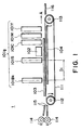
- Figure 1 is a side view of a full-line type recording device according to a first embodiment of the present invention.
- Figure 2 is a block diagram of a control circuit for the full-line type recording device of the first embodiment.
- Figure 3 is an illustration of a recording process, and ink and dot on and in the recording sheet in the first embodiment.
- Figure 4 is an illustration of a recording process, and ink and dot on and in the recording sheet in the first embodiment.
- Figure 5 is a schematic perspective view of a serial type recording device according to a second embodiment of the present invention.
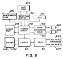
- Figure 6 is a block diagram of a control circuit of a serial type recording device according to the second embodiment.
- Figure 7 is a schematic top plan view of a major part of an apparatus to illustrate a recording process in the recording device of serial type according to second embodiment.
- Figure 8 is a side view of a full-line type recording device according to a third embodiment of the present invention.
- Figure 9 is an illustration of a process ina recording device of full-line type according to the third embodiment.
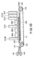
- Figure 10 is a side view of a recording device of a full-line type according to a modification of the third embodiment.
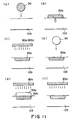
- Figure 11 is an illustration of a recording process in a recording device of a full-line type according to a modification of the third embodiment.
- Figure 12 is a schematic top plan view of a major part of a recording device of a serial type according to a fourth embodiment.
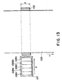
- Figure 13 is a schematic top plan view of a major part of a recording device of a serial type according to a modification of the fourth embodiment.
- Figure 14 is a schematic top plan view of a major part of a recording device of a serial type according to a fourth embodiment.
- Figure 15 is an illustration of a difference in the penetration state of the ink into the recording paper, depending on use or non-use of the heater.
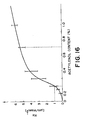
- Figure 16 shows a proportional coefficient Ka relative to the content of acetylenol in ink, empirically obtained.
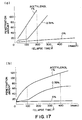
- Figure 17 is a characteristic graph showing a relation between the elapsed time and the penetration amount of the ink.
- Figure 18 shows image states of prints illustrating the difference depending on the difference in the acetylenol content when pigment ink is used.
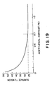
- Figure 19 is a characteristic graph showing a relation with the surface tension when content of the acetylenol in water is adjusted.
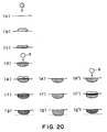
- Figure 20 illustrates a mechanism wherein -processing liquid is ejected to a deposited ink with the state wherein the ink is penetrated in the direction of the depth (thickness) to within a predetermined range in the recording material, so that coloring material of the ink reacts in the paper to insolubilized the ink.
- Figure 21 illustrates a penetration speed of ink.
- Figure 22 shows a relation between acetylenol content in ink and tw, ts.
- the processing liquid capable of reacting with and fixing a coloring material of ink is supplied to the ink which has been penetrated to the fibers of the recording material and which has started to swell ("swelled ink" which is the ink after the swell start time Ts has elapsed or the ink changed by heater or like).
- swelled ink which is the ink after the swell start time Ts has elapsed or the ink changed by heater or like.
- It may be an ultra-penetrative processing liquid, and in such a case, the fixing property is further improved by the evaporation promotion, and the coating reinforcement is accomplished.
- the second step further advantages are provided.
- the ink deposited on the recording material penetrates in the direction of the depth.
- the processing liquid is ejected to the ink to react with and insolubilized the ink, thus providing an image having high wearing property and high image quality. This will be described in conjunction with Figure 20.
- Figure 20 (f) shows a state wherein the processing liquid catches up with the penetrated ink.
- the coloring material in the ink is insolubilized by the processing liquid inside the paper, so that ink now not easily penetrates in the direction of the depth of the paper.
- the coloring material in the ink is insolubilized by the processing liquid, and the penetration stops. In this manner, not so much ink remains on the surface of the paper, but a large amount of the coloring material in the ink is insolubilized and trapped within 20 ⁇ m adjacent the surface of the paper.
- the composition of the ink, the penetration property and the penetration speed will be described.
- each ink comprises dye or pigment, water, glyceline as a solvent, diethylene glycol, urea and acetylenol EH which is a nonionic surfactant(which is a tradename of Kawaken Fine Chemical Kabushiki Kaisha, Japan, and is acetylene glycol added with ethyleneoxide, expressed by ethyleneoxide-2, 4, 7, 9-tetramethyl-5-decyne-4, 7-diol.
- acetylenol or acetylenol EH The ink used in this embodiment is a mixture of these materials.
- the color ink(CMY) 1% of acetylenol EH is added to improve the penetration property.
- Bk ink the content of the acetylenol EH is varied in the following experiments.
- Figure 17 is a characteristic graph of penetration amount of the ink vs. elapsed time, and are plots of experimental results when the recording paper has a weight of 64g/m 2 , a thickness of approx. 80 ⁇ m and a porosity approx. 50%.
- the penetration amount of the ink relative to the elapsed time increases (penetration property is higher) with increase of the content of the acetylenol. From Figure 17, it is understood that wet time tw decreases with increase of the content of the acetylenol, and in the time period not reaching tw, the penetration property is higher if the content is larger.
- the penetration property is low, and is a topping type ink which will be described hereinafter.
- the content of the acetylenol is 1%, the ink penetrates the recording paper 103 quickly, and the ink is a high-penetration ink which will be described hereinafter.
- the content of the acetylenol is 0.35%, the ink is a semi-penetrative ink.
- the wettability of the ink relative to the paper does not rise due to the sizing material, and when the used ink is a so-called topping type ink, it relatively slowly penetrates, and then the ink swells into the fibers per se from a certain point of time.
- the time is approx. 400-500msec in the case of topping type ink.
- the point of time is ts.
- the penetration speed Ka is an inclination of the liquid absorption after ts.
- the reaction therebetween occurs at the position of contact, while quite a larger part of the ink including the edge portion penetrates inside the paper but a part may remain on the surface; and the reaction advances gradually into the ink inside the paper.
- the penetration speed thereof is higher than that of the ink, and the processing liquid penetrates the ink with reaction therewith, so that penetration of the ink is stopped at a position shallower adjacent the surface of the paper than when the processing liquid is not deposited.
- the amount of the coloring material at the surface of the paper is very small, the wearing property is good.
- the content of the acetylenol is increased to more than 0.3% to raise the penetration property of the ink, the feathering occurs abruptly after ts, depending on the material of the weight, and therefore, the content (weight%) is preferably not more than0.3%.
- the penetration speed is so high that coloring material is not easily retained adjacent the surface of the paper even if the penetration speed of the processing liquid is increased, and therefore, it is preferably not more than0.3%.
- Figure 16 shows a proportional coefficient Ka relative to the content of acetylenol in ink, empirically obtained.
- the value Ka is measured using dynamic penetration property test apparatus S (available from Toyo Seiki Seisakusho, Japan) through Bristow method.
- PB sheets available from Canon Kabushiki Kaisha, Japan were used as recording paper.
- the PB sheet is usable with a copying machine or LBP of electrophotographic type and also with a printer of ink jet recording type.
- Table 1 shows typical examples of the respective contents of the topping type ink, the semi-penetrative ink and high-penetrative ink in the description of the present invention.
- Ka value (ml.m -2 .msec -1/2 ) acetylenol content (%) surface tension (dyne/cm) topping type ink - 1.0 0.0 - 0.2 40 - semi-penetrative ink 1.0 - 5.0 0.2 - 0.7 35 - 40 high-penetrative ink 5.0 - 0.7 - - 35
- Ka value, acetylenol content(%) and surface tension(dyne/cm) are given for topping type ink, semi-penetrative ink and high-penetrative ink.
- the penetration property of each ink relative to the recording paper is higher if Ka value is larger. In other words, it increases with decrease of the surface tension.
- the Ka values in Table 1 are determined by measurement using a dynamic penetration property test apparatus S, available from Toyo Seiki Seisakusho, Japan.
- the recording paper was the above-described PB sheet available from Canon Kabushiki Kaisha, Japan.
- the similar results were obtained for PPC sheet available from Canon Kabushiki Kaisha, Japan.
- the semi-penetrative ink contains 0.2-0.7% of acetylenol.
- CMC critical micelle concentration
- Figure 19 is a characteristic graph showing a relation with the surface tension when content of the acetylenol in water is adjusted. When the cell is formed, the surface tension does not decrease, and therefore, it is understood from this Figure that critical micelle concentration (CMC) of the acetylenol relative to the water is approx.0.7%.
- CMC critical micelle concentration
- the Bk ink is deposited, and then the processing liquid is printed, and thereafter, cyan (C), magenta (M) and yellow (Y) color inks are printed.
- the Bk ink is mainly used for characters and line images, and therefore, use of the ink having a low penetration property relative to the recording paper is effective as the Bk ink.
- the processing liquid was ejected after the recording was effected with the Bk ink. Then, the black coloring material was insolubilized on the surface of the recording paper, and the insolubilized coloring material remained on the surface of the recording paper, with the result that wear resistance or the overwriting resistance were not good.
- the relation between the ejection time difference and the wear resistance is such that wear resistance improves with the increase of the ejection time difference.
- the black ink is a topping or non-penetrative ink
- the processing liquid is penetrative ink
- the production of the feathering is very small when the ejection time difference from the ejection of the Bk ink to the ejection of the processing liquid is not less than approx. 1sec.
- the reacted liquid is normally produced by the mixture of the ink and the processing liquid, and since the penetration property of the reaction liquid is higher than the penetration property of the Bk ink with the result of higher probability of feathering.
- the processing liquid is ejected when the penetration of the Bk ink into the recording paper is substantially completed, and therefore, the reacted liquid is much less produced.
- the coloring material is insolubilized by the processing liquid without feathering of the topping type Bk ink.
- the time required for the completion of the penetration of the Bk ink into the recording paper can be reduced by the temperature rise. By doing so, the ejection time difference between the ejection of the Bk ink to the ejection of the processing liquid can be shortened.
- composition of the Bk ink is preferably such that 5% to 20% approx. of the diethylene glycol (DEG) for example is contained to the increase the penetration property by the rise of the temperature by the heater.
- DEG diethylene glycol
- the image quality can be improved by shorting the ejection time difference between the ejection of the ink to the ejection of the processing liquid.
- the reason is that production of the feathering can be suppressed by the processing liquid ejected before the occurrence of the feathering of the Bk ink penetrating into the recording paper, and before the Bk ink reaches deep into the recording paper, the processing liquid reacts with the ink, by which the Bk ink is insolubilized in the range close to the surface of the recording paper, and the OD value is high.
- the penetration of the Bk ink can be kept from reaching the deep position, and the feathering can be suppressed, and therefore, the time range can be expanded, and the satisfactory results can be obtained for the various nature.
- Figure 1 is a side view of a full-line type recording device according to a first embodiment of the present invention.
- the recording device 1 is of an ink jet recording type wherein the ink is ejected from a plurality of ink jet recording heads of a full-line type arranged along a feeding direction of the recording paper(arrow A), and is controlled by a control circuit shown in Figure 2 which will be described hereinafter.
- Each of the recording heads 101Bk, 101S, 101C, 101M, 101Y in the recording head group 101g is capable of effecting recording over a predetermined region in the width direction of the recording paper which is perpendicular to the vertical direction of the Figure and A direction, preferably over the entire width of the recording paper.
- Each recording head is provided with nozzles arranged substantially in the same direction as the width direction.
- the recording paper 103 is fed in the direction A by rotation of a pair of registration rollers 114 driven by a feeding motor, and is fed by a pair of guiding plates 115 so that it is fed to conveyer belt 111 with the leading edge thereof aligned with ink ejection.
- the conveyer belt 111 is in the form of an endless belt, and is supported by two.rollers 112, 113, and the vertical position thereof is limited by the platen 104 at the upper side.
- the recording paper 103 is fed by rotation of at least one of the rollers 112, 113.
- the roller is rotated by a driving source such as an unshown motor, in the direction for feeding the recording paper 103 in the direction indicated by the arrow A.
- the recording paper 103 is carried on the conveyer belt 111 and is subjected to the recording operation by the group of the recording paper heads 101g and is then discharged onto the stocker 116.
- the recording head 101Bk for the black ink, the processing liquid head 101S for ejecting the processing liquid, color ink recording head(cyan head 101C, magenta head 101M, yellow head 101Y), are arranged as shown in the Figure along the feeding direction A of the recording paper 103.
- composition of the processing liquid is as follows:
- the content of the acetylenol was adjusted for each of the examples.
- a heater 102 is provided between-the head 101S for the processing liquid and the head for the color ink, and the electric power supply control is effected such that heater 102 normally generates heat during the recording operation.
- the heater 102 is a halogen lamp heater, and the black ink ejected on the recording paper 103 is heated at the recorded surface side.
- the number of the heater is one, but a plurality of heaters may be used in consideration of the heating value per one heater and the desired heating value. The heater is used to improve the fixing property.
- the black ink head 101Bk and the processing liquid head 101S are disposed with a predetermined clearance Di therebetween, and the ejection time difference between the ejection of the black ink and the ejection of the processing liquid is determined in accordance with the predetermined interval and the feeding speed of the recording paper 103.
- the feeding speed of the recording paper 103 is controlled to provide the ejection time difference of approx. lsec so as to provide dot processing liquids.
- the clearance between the black ink head 101Bk and the processing liquid head 101S is determined in compliance with the feeding speed.
- Figure 2 is a block diagram of the control circuit in the recording device 1 of the full-line type.
- system controller 201 there are provided a micro-processor, a storing medium (ROM) storing the program for controlling device and processes, and storing material (RAM) for the operation of the micro-processor.
- the system controller 201 controls the entirety of the apparatus.
- the motor 204 operates in accordance with received information such as the speed or movement distance from the driver 202, and feeds the sheet-like recording material such as a recording paper in the direction of arrow A in Figure 1.
- a host computer 206 functions to transfer the information to be recorded into the recording device 1 of this embodiment.
- a reception buffer 207 temporarily stores the data from the host computer 206, and accumulates them until the data from the system controller 201 is received.
- a frame memory 208 is a memory for converting the data to be printed to the image data, and has a memory size necessary for the printing. In this embodiment, the frame memory 208 is capable of storing data for one page of the recording paper, but the present invention is not limited to this.
- Buffers 209S, 209P temporarily stores the data to be printed, and the storing capacity is different if the nozzle number of the recording head is different.
- a print controller 210 functions to control the recording head in accordance with the instructions from the system controller 201, and controls the printing speed, print data number or the like, and further it generates the data for ejecting the processing liquid.
- a driver 211 drives the recording head 212S for ejecting the processing liquid and the recording head 212P for ejecting the ink for the image recording, and is controlled by the signal from the- print controller 210.
- the image data is supplied from the host computer 206 to the reception buffer 207, and is temporarily stored there. Then, the image data stored are reader by the system controller 201 and are converted into the buffers 209S, 209P.
- the system controller 201 controls the electric energization to the heater 102. Malfunction such as sheet jam, ink shortage, sheet shortage or the like can be detected by detection signals from an abnormality sensor 222.
- the print controller 210 generates the data for the processing liquid for ejecting the processing liquid on the basis of the image data in the buffer 209S, 209P.
- the ejecting operation of the recording heads are controlled on the basis of the data for the processing liquid and the image data in the buffers 209S, 209P.
- the black ink has a topping property in Table 1.
- the processing liquid has a certain degree of penetration property, and the acetylenol content is approx.0.4-1.0%.
- the black ink droplet 30 is ejected by black ink head 101Bk ( Figure 3, (a)).
- the black ink droplet 30a is deposited on the recording paper surface, and penetrates as indicated by white arrow to the range indicated by the broken lines in the recording paper before the processing liquid droplet is ejected by the processing liquid head 101S ( Figure 3, (b)).
- the ejection time difference from the ejection of the black ink and the ejection of the processing liquid is approx. lsec.
- the black ink droplet 30a ejected from the head 101Bk for the black ink penetrates into the recording paper 103.
- a droplet 35 of the processing liquid(record improving liquid) having a certain degree of penetration property is ejected onto the dot 30b provided by the ejection of the ink from the black ink head 101Bk ( Figure 3, (c)).
- the rapid swell start point ts has been exceeded.
- the processing liquid and the dye in the black ink react to insolubilized the dye in the recording paper 103.
- the dot 30b provided by the black ink and the processing liquid droplet 35a ejected on the dot 30b are heated by the heater 102 ( Figure 3, (d)), by which the evaporations of the water content in the black ink and in the solvent of the processing liquid are promoted, so that reaction speed and the fixing property are enhanced ( Figure 3, (e)).
- the heating with the heater is not necessary, but the strength of the reaction liquid coating is improved by the heating.
- the heat provides the effects substantially similarly to the ultra-penetrative.
- the black ink droplet 30 is ejected, and the processing liquid droplet 35 is ejected to be overlaid thereon with a delay of not less than said ts to permit certain degree of penetration of the black ink into the recording paper(approx. lsec), so that ink can be insolubilized inside the recording paper.
- the ink is insolubilized when it penetrates in the recording paper 103, so that wear resistance and the overwriting resistance as well as the recording paper 103 can be improved.
- Figure 4 shows the state of the ink and dot on and in the recording paper 103 when the color ink droplet 40 is ejected adjacent to the dot 30b provided by the black ink droplet 30 after the process shown in Figure 3, (d).
- the color ink droplet 40 is deposited on the surface of the recording paper 103, as a color ink droplet 40a.
- the ink ejected by the color ink head (101C, 101M, 101Y) is a high-penetrative ink described above, and therefore, the penetration speed into the recording paper 103 is high, and the spread does not easily occur even if the other color ink is deposited to the neighborhood thereof.
- the black ink droplet 30 is a topping type ink which has a low penetration property than the color ink. Therefore, when another color ink droplet is deposited to the position adjacent thereto, the spread easily occurs.
- the processing liquid droplet 35b is overlaid on the dot 30b of black ink droplet 30, and the black ink is heated by the heater 102 if necessary, the ink is insolubilized in the recording paper 103.
- the water-resistance can be provided for the color print.
- a heater having a small heating value may be added between the head 101Bk for the black ink and the head 101S for the processing liquid( Figure 1), by which the penetration of the black ink from the head 101Bk may be promoted into the recording paper 103.
- the penetration of the black ink into the recording paper 103 may be promoted by using black ink containing 0.3% of the acetylenol so that penetration property is slightly higher than the topping type ink.
- the ts can be effectively shorted, and therefore, good images can be formed even with the ejection time difference reduced to less than lsec, so that clearance between the black ink head 101Bk and the processing liquid head 101S, thus permitting downsizing of the apparatus.
- the feeding speed of the recording paper 103 can be raised. The feeding speed is to be determined in consideration of the recording speed at which the recording head can properly eject the ink.
- a processing liquid head 101 may be added downstream of the heads 101C, 101M, 101Y for the color inks with respect to the feeding direction A of the recording paper 103, so that processing liquid is ejected also to the dot provided by the color ink, by which the water-resistance of the color ink image can be improved.
- Figure 5 is a schematic perspective view of a structure of a recording device 5 of a serial type.
- the recording paper 103 (recording material) is supplied from the sheet feeder 105 and is discharged through the printing portion 126.
- the inexpensive plain paper is used as the recording paper 103.
- the printing portion 126 is provided with a recording head 101 carried on a carriage 107, and the recording head 101 is reciprocable along the guiding rail 109 by a motor 604 shown in Figure 6.
- the recording head 101 has a black ejection portion 108Bk for ejecting black ink, a processing liquid ejecting portion 108S for ejecting processing liquid, and cyan ejection portion 108C, magenta ejection portion 108M and yellow ejection portion 108Y for ejecting the respective color inks.
- the ink is supplied from unshown ink container, and the driving signal is supplied to the electrothermal transducer(heater) for ejecting the liquid provided in each of the nozzles.
- the driving signal is supplied to the electrothermal transducer(heater) for ejecting the liquid provided in each of the nozzles.
- a bubble is generated in the ink by thermal energy applied to the ink, and the ink is ejected by the pressure resulting from the bubble generation.
- a so-called bubble jet type is used for the ink ejection.
- Ejection outlets in the ejection portion are arranged in a perpendicular direction relative to the movement direction of the recording head 101, that is, in the same direction as the feeding direction X of the recording paper 103.
- a heater 102 is provided so as to cover the entire area of the movement range of the carriage 107 at a position opposed to each of the ejection portions.
- the heater 102 is in close contact to the recording paper 103 at the back side of the recording paper 103, and the heater 102 is a ceramic heater which is suitable for the heating of the surface contacted thereto.
- the recording head 101 effects the recording at the resolution of 360dpi, and the driving frequency of the electrothermal transducer is 7.2kHz.
- the carriage 107 completes one reciprocation in 1.5sec.
- Figure 6 is a block diagram of the control circuit for the recording device 5 of the serial type.
- the same reference numerals as in Figure 2 are assigned to the elements having the corresponding functions, and detailed descriptions thereof are omitted for simplicity.
- the motor 604 of Figure 6 receives information such as a movement distance and speed from the driver 602 and operates in accordance with the information to drive the recording head in the main-scanning direction(scanning direction).
- the motor 605 receives information such as a movement distance and a speed from the driver 602 and operates in accordance with the information to feed the sheet-like recording material such as recording paper in a sub-scan direction(feeding direction).
- Figure 7 illustrates a recording process of the recording device of the serial type shown in Figures 5 and 6, and is a plan view of the recording station 126.
- the carriage 107 reciprocates in X direction which is substantially perpendicular to the feeding direction Y above the recording paper 103 fed in the Y direction in close contact with the heater 102.
- the ejection outlets (indicated by dots in the Figure) of the black ejection portion 108Bk, the processing liquid ejecting portion 108S, the color ejecting portion (108C, 108M, 108Y) carried on the carriage 107, are opening in the direction of the ejection of the ink and the processing liquid against the recording paper 103.
- the heater 102 generates heat during the recording operation, and is provided at a position opposing to the region to which the liquid is ejected by the processing liquid ejecting portion 108S and the color ejecting portions 108C, 108M, 108Y.
- Each ejection portion has ejection outlets arranged to effect the recording in the width d along the feeding direction Y of the recording paper 103 by one scanning.
- the black ejection portion 108Bk and the processing liquid ejecting portion 108S are disposed with deviation by the recording width d in the feeding direction.
- the ejection time difference corresponds to the substantial completion of the penetration of the black ink to the predetermined range in the direction of the thickness of the recording paper.
- the ejection of the ink by the black ejection portion 108Bk to the predetermined position of the recording paper 103 and the ejection of the processing liquid by the processing liquid ejecting portion 108S are effected with the deviation corresponding to one scan of the carriage 107 (scanning period is 1.5sec), thus providing the predetermined time difference.
- the recording process which is substantially similar to the recording process of the recording device of the full-line type according to the first embodiment is accomplished in the recording device of a serial type.
- the black ink is ejected by the black ejection portion 108Bk in the first scanning.
- the region in which the black ink is ejected is upstream of the position of the heater 102, and is not heated by the heater 102.
- the sheet is fed by the recording width d with a time delay to permit the penetration of the black ink into the recording paper 103, and the next scanning is effected to the same region on the heater 102, so that processing liquid droplet is ejected to be overlaid on the dot formed by the black ink, by the processing liquid ejecting portion 108S.
- the heat generation of the heater 102 is effective to promote the evaporations of water content contained in the black ink and in the solvent of the processing liquid, so that fixing property is improved, and the coloring material in the ink is insolubilized in the recording paper 103.
- the heater 102 is provided at the back side of the recording paper 103 in the region where the ejection portion (108C, 108M, 108Y) for ejecting the color ink eject the ink, so that fixing property of the color ink can be improved.
- Figure 8 is a side view of a full-line type recording device according to a third embodiment of the present invention.
- the same reference numerals as in Figure 1 are assigned to the elements having the corresponding functions, and detailed descriptions thereof are omitted for simplicity.
- the recording device of Figure 8 is similar to the recording device 1 of Figure 1, but has an additional heaters 80a, 80b between the head 101Bk for the black ink and the head 101S for the processing liquid, and the black ink has a semi-penetrative property.
- the processing liquid has a penetration property higher than the black ink.
- the heating of the heaters 80a, 80b is effected after the black ink ejection, the penetration of the black ink is substantially confined in the region adjacent the surface of the recording paper 103, so that record density is high.
- the processing liquid is ejected by the head 101S with this state, and therefore, the black ink can be insolubilized while the penetration of the black ink is confined adjacent the surface of the recording paper 103.
- the black ink droplet 30 is ejected by black ink head 101Bk ( Figure 9, (a)).
- the black ink droplet 30a is deposited on the recording paper surface, and penetrates as indicated by white arrow ( Figure 9, (b)).
- the dot 30b formed on the recording paper 103 is heated by the heaters 80a, 80b, and the evaporation of the water content is promoted during this period so that fixing property is improved, and the penetration of the ink into the recording paper 103 is suppressed. Therefore, hardly any ink remains on the surface of the recording paper 103, and the processing liquid is ejected and overlaid thereon after the state of Figure 9, (c) is reached wherein the ink is penetrated to a shallow position from the surface of the recording paper 103.
- the processing liquid droplet 35 is ejected to be overlaid on the dot 30b formed by the ejection of the ink by the black ink head 101Bk, by the processing liquid head 101S.
- the penetration of the black ink further into the recording paper 103 can be suppressed, and therefore, the image density of the black ink can be further improved.
- the processing liquid is ejected, so that black ink is insolubilized inside the recording paper 103.
- the wear resistance and the overwriting resistance as well as the water-resistance are improved. Since the penetration of the black ink to the deep position of the recording paper 103 can be suppressed, so that density of the image of the black ink can be increased, and therefore, the sharp characters and line images can be provided.
- the processing liquid Since the processing liquid has a higher penetration property than the black ink, the processing liquid penetrates into the recording paper 103 at a speed higher than the penetration speed of the black ink and reacts with the black ink, so that penetration of the black ink into the recording paper 103 can be suppressed.
- the solvent separated by the insolubilization of the coloring material of the black ink penetrates into the recording paper 103, so that fixing property is improved.
- Figure 10 is a side view of a recording device of a full-line type according to a modification of the third embodiment.
- the same reference numerals as in Figure 8 are assigned to the elements having the corresponding functions, and detailed descriptions thereof are omitted for simplicity.
- the recording device of Figure 10 is the same as the recording device of Figure 8 except that heater 80c is added between the head 101S for the processing liquid and the head 101C for the color (C) ink. With this structure, the heating by the heater 80c is carried out also after the processing liquid ejection.
- the heating by the heater is carried out after the ejection of the black ink droplet 30, and then, the processing liquid droplet 35 is ejected to and overlaid on the dot 30b ( Figure 11, (a)-(b)).
- the heater 80c effects the heating ( Figure 11, (e)).
- the dot 30b provided by the black ink and the processing liquid droplet 35b ejected to be overlaid on the dot 30b are heated, so that evaporations in the water content in the black ink and the solvent of the processing liquid are promoted ( Figure 11, (f)).
- the possible flow of the insolubilized coloring material with the penetration of the solvent can be prevented, so that sort of feathering can be prevented, and therefore, the image quality of the characters and the line images of the black ink can be further improved.
- the general arrangement of the recording device of this embodiment is the same as that of Figure 5, and Figure 12 schematically is a top plan view of the recording station (126).
- the recording device is intended to accomplish the recording process which is the same as the recording process of the recording device of the full-line type according to the third embodiment, in a serial type.
- the black ejection portion 108Bk and the processing liquid ejecting portion 108S are deviated by the recording width d in the feeding direction Y.
- the black ink is ejected by the black ejection portion 108Bk, and then it is heated by the heater 102 to a predetermined degree, and thereafter, the processing liquid and the color ink are sequentially ejected.
- the heater 102 is disposed in close contact to the back side of the recording paper, so that regions for the ejections by the black ejection portion 108Bk and the processing liquid ejecting portion 108S are the same.
- the scanning by all heads is completed by the two scans with a time difference therebetween, so that coloring material in the black ink is prevented from insolubilizing at the surface of the recording paper.
- the black ejection portion 108Bk ejects the black ink.
- a second recording scan is effected, a predetermined period thereafter, to eject the processing liquid by the processing liquid ejecting portion 108S and the ejection of the color inks (cyan, magenta and yellow) by the color ejection portions (108C, 108M, 108Y).
- the recording paper 103 is fed by the recording width d, and the divided scannings are repeated.
- the heater 102 is kept on during the recording operation, but since the scanning is divided into two scans, the desired heating is effected so that same effects as in the third embodiment are provided.
- the order of arrangement of the black ink ejecting portion 108Bk, the processing liquid ejecting portion 108S and the color ejection portions 108C, 108M, 108Y, is not limited by the feeding direction of the carriage 107 (direction X in the Figure).
- the color ejecting portions 108Y, 108M, 108C, black ejection portion 108Bk and processing liquid ejecting portion 108S may be arranged in this order in the X direction from the left side in the Figure on the carriage 107, in which case, the black ejection portion 108Bk is operated by the first recording scan, and the processing liquid ejecting portion 108S and the color ejection portions are operated in the second recording scan to eject the processing liquid and the color ink.
- a recording device of this embodiment is the same as that of Figure 5 (serial type), and Figure 14 is a top plan view of the recording station (126) of this apparatus.
- the black image is recorded by two scans (divided recording), the black image formed by the first recording scan is supplemented by the second recording scan to complete the black image.
- the second scanning is carried out with the predetermined time difference as in the foregoing embodiment.
- the other color images they are formed through one scan.
- the black ejection portion 118Bk has ejection outlets capable of providing the recording width 2d which is twice the recording width d of the other ejection portions (processing liquid ejecting portion 108S and the color ejecting portions 108C, 108M, 108Y).
- each ejection portion has an array of the ejection outlets in the feeding direction Y of the recording paper 103.
- the ejection outlets are arranged in the Y direction so as to cover the width d at a position corresponding to the position of the heater 102, but in the black ejection portion 118Bk, the ejection outlets are arranged over the width 2d.
- the region which is recorded by the black ejection portion 118Bk in the first ejecting scan, is deviated by the recording width d relative to the region recorded by the other ejection portions toward upstream in the feeding direction.
- the recording paper 103 is fed by the distance corresponding to the recording width d in the y direction, and the recording operation by one scan of the carriage 107 and the feeding operation of the recording paper 103 are repeated to effect the recording substantially on the entire area on the recording paper 103.
- the recording width 2d of the black ejection portion 118Bk is wider than the recording width d of the other ejection portion, and therefore, the black ejection portion 118Bk scans twice as much as the other recording region.
- the black ejection portion 118Bk effects a skipped recording in each of the two scans so that image is completed by two scans.
- an upstream side (upper side in the Figure), with respect to the recording paper feeding direction Y, of the recording width 2d is scanned by the first scan of the black ejection portion 118Bk, and the downstream(lower side in the Figure) side thereof is scanned by the second scan.
- the ejection outlets at the upstream side of the black ejection portion 118Bk is used, and the black image is recorded in the skipped manner without heating by the heater 2.
- the recording paper 103 is fed in the Y direction by the pitch corresponding to the recording width d.
- the downstream side ejection outlets of the black ejection portion 118Bk is used, to effect the recording for the part skipped in the first scan to supplement the skipped portion (divided ejection of the black ejection portion 118Bk).
- the first and second scans of the black ejection portion 118Bk are complementary with each other to complete the black image, by which the amount of the black ink ejected by one scan can be reduced.
- the pattern of the skip may be a staggered pattern or inverse staggered pattern (checker pattern).
- the region which has been recorded by the upstream ejection outlet of the black ejection portion 118Bk is subjected in the next scan to the recording by the downstream ejection outlets, the ejection of the processing liquid by the processing liquid ejecting portion 108S, the ejection of the color ink by the color ejecting portions 108C, 108M, 108Y, and the heating by the heater 102.
- the ejection amount of the black ink in one scan by the black ejection portion 118Bk is reduced, and the amount of the ink ejected to a neighborhood of another ink is can be minimized, as compared with the single scan.
- the staggered and inverse staggered patterns are used for the skipping, the ejection to the neighborhood position in X and Y directions in the Figure, does not occur.
- the overflow of the ink or flow of the ink which may occur when a great number of ink droplets are deposited at adjacent positions do not occur, so that boundary of the black image can be made further sharp.
- the ejection time difference between the ejection of the black ink by the downstream(lower side in the Figure) ejection outlet of the black ejection portion 118Bk and the ejection of the processing liquid by the processing liquid ejecting portion 108s, is shorter than in the second embodiment.
- the black ink already ejected by the upstream(upper side in the Figure) ejection outlet has been penetrated into the recording paper 103 at the time of the next scan, and when the ink is deposited to a position adjacent the position at which the black ink is penetrated, the penetration of the later deposited ink is promoted. Therefore, even if the processing liquid is ejected continuously, the ink has been penetrated into the recording paper 103, so that coloring material of the ink can be insolubilized at a shallow position in the recording paper 103.
- the heater 102 has been described as being in operation normally, it may be turned off when an abnormality sensor 222 detects an abnormality such as sheet jam or the like, the electric energization may be stopped to stop the heat generation operation by using a system controller 201 ( Figure 2, 6).
- the present invention is particularly suitably usable in an ink jet recording head and recording apparatus wherein thermal energy by an electrothermal transducer, laser beam or the like is used to cause a change of state of the ink to eject or discharge the ink. This is because the high density of the picture elements and the high resolution of the recording are possible.
- the typical structure and the operational principle are preferably the ones disclosed in U.S. Patent Nos. 4,723,129 and 4,740,796.
- the principle and structure are applicable to a so-called on-demand type recording system and a continuous type recording system.
- it is suitable for the on-demand type because the principle is such that at least one driving signal is applied to an electrothermal transducer disposed on a liquid (ink) retaining sheet or liquid passage, the driving signal being enough to provide such a quick temperature rise beyond a departure from nucleation boiling point, by which the thermal energy is provided by the electrothermal transducer to produce film boiling on the heating portion of the recording head, whereby a bubble can be formed in the liquid (ink) corresponding to each of the driving signals.
- the liquid (ink) is ejected through an ejection outlet to produce at least one droplet.
- the driving signal is preferably in the form of a pulse, because the development and contraction of the bubble can be effected instantaneously, and therefore, the liquid (ink) is ejected with quick response.
- the driving signal in the form of the pulse is preferably such as disclosed in U.S. Patents Nos. 4,463,359 and 4,345,262.
- the temperature increasing rate of the heating surface is preferably such as disclosed in U.S. Patent No. 4,313,124.
- the structure of the recording head may be as shown in U.S. Patent Nos. 4,558,333 and 4,459,600 wherein the heating portion is disposed at a bent portion, as well as the structure of the combination of the ejection outlet, liquid passage and the electrothermal transducer as disclosed in the above-mentioned patents.
- the present invention is applicable to the structure disclosed in Japanese Laid-Open Patent Application No. 123670/1984 wherein a common slit is used as the ejection outlet for plural electrothermal transducers, and to the structure disclosed in Japanese Laid-Open Patent Application No. 138461/1984 wherein an opening for absorbing pressure wave of the thermal energy is formed corresponding to the ejecting portion. This-is because the present invention is effective to perform the recording operation with certainty and at high efficiency irrespective of the type of the recording head.
- the present invention is effectively applicable to a so-called full-line type recording head having a length corresponding to the maximum recording width.
- a recording head may comprise a single recording head and plural recording head combined to cover the maximum width.
- the present invention is applicable to a serial type recording head wherein the recording head is fixed on the main assembly, to a replaceable chip type recording head which is connected electrically with the main apparatus and can be supplied with the ink when it is mounted in the main assembly, or to a cartridge type recording head having an integral ink container.
- the provisions of the recovery means and/or the auxiliary means for the preliminary operation are preferable, because they can further stabilize the effects of the present invention.
- preliminary heating means which may be the electrothermal transducer, an additional heating element or a combination thereof.
- means for effecting preliminary ejection (not for the recording operation) can stabilize the recording operation.
- the recording head mountable may be a single corresponding to a single color ink, or may be plural corresponding to the plurality of ink materials having different recording color or density.
- the present invention is effectively applicable to an apparatus having at least one of a monochromatic mode mainly with black, a multi-color mode with different color ink materials and/or a full-color mode using the mixture of the colors, which may be an integrally formed recording unit or a combination of plural recording heads.
- the ink jet recording apparatus may be used as an output terminal of an information processing apparatus such as computer or the like, as a copying apparatus combined with an image reader or the like, or as a facsimile machine having information sending and receiving functions.
- the mixture occurs on the recording material on or in the recording material, a low molecular weight component of the cation materials or the cation oligomer in the processing liquid and the anionic chemical compound in the pigment ink or the water-soluble dye having the anionic base causes association, and instantaneously separation from the liquid phase occurs, in the first stage of the reaction.
- a low molecular weight component of the cation materials or the cation oligomer in the processing liquid and the anionic chemical compound in the pigment ink or the water-soluble dye having the anionic base causes association, and instantaneously separation from the liquid phase occurs, in the first stage of the reaction.
- the association product of the dye and the low molecular cationic material or the cation oligomer or the coagulated material of the pigment is attracted by the polymeric component contained in the processing liquid, and therefore, the size of the coagulated material of the dye or of the coagulated material of the pigment is increased, so that they are not easily enter the gaps between the fibers; as a result, only the liquid portion resulting from the solid-liquid separation enters the recording paper, and the print quality and the fixing property are both accomplished.
- the coagulated material formed by the cation material and the anionic dye and the cation oligomer or the low molecular component of the cation substance, or the coagulated material of the pigment, thus produced have high viscosity, and do not move with the liquid, and therefore, the inks of different colors at adjacent positions do not mix together, and not bleeding occurs.
- the coagulated material is essentially non-water-soluble, and therefore, the water-resistance of the final image is high.
- the light resistance of the image formed by the shield effect of the polymer is improved.
- Insolubilization and coagulation occurs only in the first stage in one example, and they occur in both of the first and second stages in another example.
- the recording material used with the present invention is not limited to a particular one, the conventional copy sheet, bond paper or anther plain paper is usable. Coated paper for ink jet print, transparent film for OHP, usual high class paper or glossy paper are usable.
- the present invention method is usable in a system comprising a plurality of machines, or a single machine.
- the present invention method may be implemented by supplying program to a system or an apparatus.
- a storing medium storing program(software) for implementing the present invention method is read out by the system or the apparatus, and this invention method is actually implemented in the system or the apparatus.
- the image quality, the water-resistance immediately after the printing, the wear resistance and the overwriting resistance are improved.
Landscapes
- Ink Jet Recording Methods And Recording Media Thereof (AREA)
- Ink Jet (AREA)
Applications Claiming Priority (3)
| Application Number | Priority Date | Filing Date | Title |
|---|---|---|---|
| JP21637397 | 1997-08-11 | ||
| JP21637397 | 1997-08-11 | ||
| JP216373/97 | 1997-08-11 |
Publications (4)
| Publication Number | Publication Date |
|---|---|
| EP0897800A2 true EP0897800A2 (de) | 1999-02-24 |
| EP0897800A3 EP0897800A3 (de) | 2000-08-23 |
| EP0897800B1 EP0897800B1 (de) | 2004-12-22 |
| EP0897800B8 EP0897800B8 (de) | 2005-03-30 |
Family
ID=16687564
Family Applications (1)
| Application Number | Title | Priority Date | Filing Date |
|---|---|---|---|
| EP98306383A Expired - Lifetime EP0897800B8 (de) | 1997-08-11 | 1998-08-10 | Aufzeichnungsverfahren |
Country Status (3)
| Country | Link |
|---|---|
| US (1) | US6916092B2 (de) |
| EP (1) | EP0897800B8 (de) |
| DE (1) | DE69828227T2 (de) |
Cited By (3)
| Publication number | Priority date | Publication date | Assignee | Title |
|---|---|---|---|---|
| US6454402B1 (en) * | 1998-12-24 | 2002-09-24 | Canon Kabushiki Kaisha | Ink-jet printing method an ink-jet printing apparatus |
| EP1208989A3 (de) * | 2000-11-17 | 2003-10-22 | Canon Kabushiki Kaisha | Apparat und Verfahren zum Tintenstrahldrucken |
| EP1527892A1 (de) * | 2003-10-29 | 2005-05-04 | Konica Minolta Medical & Graphic, Inc. | Tintenstrahlaufzeichnungsvorrichtung |
Families Citing this family (11)
| Publication number | Priority date | Publication date | Assignee | Title |
|---|---|---|---|---|
| JPWO2005002867A1 (ja) * | 2003-07-07 | 2006-08-10 | ソニー株式会社 | インクジェット記録方法及びインクジェットプリンター |
| JP4812078B2 (ja) | 2004-12-28 | 2011-11-09 | キヤノン株式会社 | インクジェット記録装置 |
| KR20060116548A (ko) * | 2005-05-10 | 2006-11-15 | 삼성전자주식회사 | 잉크젯 프린터 |
| JP4822759B2 (ja) * | 2005-07-28 | 2011-11-24 | 富士フイルム株式会社 | 画像形成装置 |
| JP2007137049A (ja) * | 2005-10-19 | 2007-06-07 | Ricoh Co Ltd | 画像処理方法、プログラム、画像処理装置、画像形成装置及び画像形成システム |
| US20080117273A1 (en) * | 2006-11-16 | 2008-05-22 | Fuji Xerox Co., Ltd. | Image recording device and image recording method |
| JP2009096187A (ja) * | 2007-09-28 | 2009-05-07 | Fujifilm Corp | 画像形成方法及びインクジェット記録装置 |
| JP4780347B2 (ja) * | 2008-10-10 | 2011-09-28 | 富士ゼロックス株式会社 | 画像形成装置及び画像形成方法 |
| CN102481791A (zh) | 2009-09-14 | 2012-05-30 | 富士胶片株式会社 | 喷墨印刷方法和装置 |
| US10647144B2 (en) | 2018-02-23 | 2020-05-12 | Canon Kabushiki Kaisha | Ink jet recording method |
| JP2024103134A (ja) * | 2023-01-20 | 2024-08-01 | セイコーエプソン株式会社 | 記録方法及び記録装置 |
Citations (3)
| Publication number | Priority date | Publication date | Assignee | Title |
|---|---|---|---|---|
| JPS58128862A (ja) | 1982-01-26 | 1983-08-01 | Minolta Camera Co Ltd | インクジエツト記録方法 |
| JPH08204618A (ja) | 1995-01-24 | 1996-08-09 | Nec Corp | エコーキャンセラ装置 |
| JPH1044394A (ja) | 1996-08-02 | 1998-02-17 | Canon Inc | インクジェット記録方法およびインクジェット記録装置 |
Family Cites Families (23)
| Publication number | Priority date | Publication date | Assignee | Title |
|---|---|---|---|---|
| JPS5443733A (en) * | 1977-09-13 | 1979-04-06 | Toyo Ink Mfg Co | Printing method |
| CA1127227A (en) | 1977-10-03 | 1982-07-06 | Ichiro Endo | Liquid jet recording process and apparatus therefor |
| JPS5936879B2 (ja) | 1977-10-14 | 1984-09-06 | キヤノン株式会社 | 熱転写記録用媒体 |
| US4330787A (en) | 1978-10-31 | 1982-05-18 | Canon Kabushiki Kaisha | Liquid jet recording device |
| US4345262A (en) | 1979-02-19 | 1982-08-17 | Canon Kabushiki Kaisha | Ink jet recording method |
| US4463359A (en) | 1979-04-02 | 1984-07-31 | Canon Kabushiki Kaisha | Droplet generating method and apparatus thereof |
| US4313124A (en) | 1979-05-18 | 1982-01-26 | Canon Kabushiki Kaisha | Liquid jet recording process and liquid jet recording head |
| US4558333A (en) | 1981-07-09 | 1985-12-10 | Canon Kabushiki Kaisha | Liquid jet recording head |
| JPS59123670A (ja) | 1982-12-28 | 1984-07-17 | Canon Inc | インクジエツトヘツド |
| JPS59138461A (ja) | 1983-01-28 | 1984-08-08 | Canon Inc | 液体噴射記録装置 |
| JPS6071260A (ja) | 1983-09-28 | 1985-04-23 | Erumu:Kk | 記録装置 |
| JP3283935B2 (ja) * | 1992-09-17 | 2002-05-20 | キヤノン株式会社 | インクセット、インクジェット記録方法および画像の品位を向上させる方法 |
| JPH06228478A (ja) * | 1993-02-04 | 1994-08-16 | Canon Inc | インクセット及びこれを用いたカラー画像の形成方法 |
| JPH06239013A (ja) * | 1993-02-22 | 1994-08-30 | Fuji Xerox Co Ltd | インクジェット記録方法 |
| JPH0796603A (ja) | 1993-07-31 | 1995-04-11 | Sony Corp | インクジェット記録装置 |
| JPH0747762A (ja) * | 1993-08-09 | 1995-02-21 | Fuji Xerox Co Ltd | インクジェット記録方法及びその装置 |
| US5614931A (en) * | 1993-08-26 | 1997-03-25 | Fuji Xerox Co., Ltd. | Ink jet recording method |
| JP3288867B2 (ja) * | 1994-09-02 | 2002-06-04 | キヤノン株式会社 | インクジェット記録装置 |
| JP3376183B2 (ja) * | 1994-09-29 | 2003-02-10 | キヤノン株式会社 | インクジェット用水性インク、インクジェット記録方法及びブリード緩和方法 |
| JP3190535B2 (ja) | 1995-02-13 | 2001-07-23 | キヤノン株式会社 | インクジェットプリント装置およびインクジェットプリント方法 |
| US6102537A (en) | 1995-02-13 | 2000-08-15 | Canon Kabushiki Kaisha | Method and apparatus for ink-jet printing |
| JP3320292B2 (ja) * | 1995-02-13 | 2002-09-03 | キヤノン株式会社 | インクジェットプリント装置およびインクジェットプリント方法 |
| EP0897805B1 (de) * | 1997-08-08 | 2004-12-29 | Canon Kabushiki Kaisha | Tintenstrahlaufzeichnungs- Verfahren und Vorrichtung |
-
1998
- 1998-08-10 DE DE69828227T patent/DE69828227T2/de not_active Expired - Lifetime
- 1998-08-10 EP EP98306383A patent/EP0897800B8/de not_active Expired - Lifetime
- 1998-08-10 US US09/131,744 patent/US6916092B2/en not_active Expired - Fee Related
Patent Citations (3)
| Publication number | Priority date | Publication date | Assignee | Title |
|---|---|---|---|---|
| JPS58128862A (ja) | 1982-01-26 | 1983-08-01 | Minolta Camera Co Ltd | インクジエツト記録方法 |
| JPH08204618A (ja) | 1995-01-24 | 1996-08-09 | Nec Corp | エコーキャンセラ装置 |
| JPH1044394A (ja) | 1996-08-02 | 1998-02-17 | Canon Inc | インクジェット記録方法およびインクジェット記録装置 |
Cited By (7)
| Publication number | Priority date | Publication date | Assignee | Title |
|---|---|---|---|---|
| US6454402B1 (en) * | 1998-12-24 | 2002-09-24 | Canon Kabushiki Kaisha | Ink-jet printing method an ink-jet printing apparatus |
| EP1208989A3 (de) * | 2000-11-17 | 2003-10-22 | Canon Kabushiki Kaisha | Apparat und Verfahren zum Tintenstrahldrucken |
| EP1527892A1 (de) * | 2003-10-29 | 2005-05-04 | Konica Minolta Medical & Graphic, Inc. | Tintenstrahlaufzeichnungsvorrichtung |
| US7458673B2 (en) | 2003-10-29 | 2008-12-02 | Konica Minolta Medical & Graphic Inc. | Ink jet recording apparatus |
| US7651215B2 (en) | 2003-10-29 | 2010-01-26 | Konica Minolta Medical & Graphic, Inc. | Ink jet recording apparatus |
| US7651214B2 (en) | 2003-10-29 | 2010-01-26 | Konica Minolta Medical & Graphic, Inc. | Ink jet recording apparatus |
| US7798632B2 (en) | 2003-10-29 | 2010-09-21 | Konica Minolta Medical & Graphic Inc. | Ink jet recording apparatus |
Also Published As
| Publication number | Publication date |
|---|---|
| EP0897800B1 (de) | 2004-12-22 |
| DE69828227D1 (de) | 2005-01-27 |
| DE69828227T2 (de) | 2005-12-15 |
| EP0897800B8 (de) | 2005-03-30 |
| US6916092B2 (en) | 2005-07-12 |
| EP0897800A3 (de) | 2000-08-23 |
| US20040201656A1 (en) | 2004-10-14 |
Similar Documents
| Publication | Publication Date | Title |
|---|---|---|
| EP0925919B1 (de) | Tintenstrahldruckapparat | |
| KR100458540B1 (ko) | 잉크 제트 인쇄 방법 및 장치 | |
| EP0897800B1 (de) | Aufzeichnungsverfahren | |
| EP2116381B1 (de) | Tintenstrahldruckapparat | |
| KR100338617B1 (ko) | 잉크의 색재를 불용화시키는 기능을 가진 잉크를 사용하여 프린트하는 잉크 프린트 방법 및 잉크젯 프린트 장치 | |
| US6550904B2 (en) | Ink printing method and ink printer | |
| US6474778B1 (en) | Ink jet printing apparatus and ink jet printing method | |
| JP4616975B2 (ja) | インクジェットプリント方法および装置 | |
| EP0595651B1 (de) | Tintenstrahlaufzeichnungssystem | |
| EP1057646A2 (de) | Erzeugung von Tintenbildern mit einem Schutzfilm | |
| EP0822087B1 (de) | Tintenstrahldruckverfahren und Tintenstrahldruckapparat | |
| US6471348B1 (en) | Ink printing method and ink printer | |
| EP0847872B1 (de) | Tintenstrahldruckverfahren, das eine erste und eine zweite Flüssigkeit verwendet, und eine Druckvorrichtung für dieses Verfahren | |
| EP1066968B1 (de) | Tintenstrahldruckvorrichtung und Tintenstrahldruckverfahren | |
| JP4343329B2 (ja) | インクプリント方法およびインクジェットプリント装置 | |
| JP3658196B2 (ja) | 記録方法 | |
| EP0858900A2 (de) | Tintenstrahldruckgerät und Tintenstrahldruckverfahren | |
| JP3667097B2 (ja) | インクジェット記録方法およびインクジェット記録装置 | |
| JP4036463B2 (ja) | インクジェットプリント装置およびプリント方法 | |
| JPH08323968A (ja) | 画像処理装置及びその方法 | |
| JPH10226088A (ja) | インクジェット記録装置および記録ヘッドの吐出回復処理方法 |
Legal Events
| Date | Code | Title | Description |
|---|---|---|---|
| PUAI | Public reference made under article 153(3) epc to a published international application that has entered the european phase |
Free format text: ORIGINAL CODE: 0009012 |
|
| AK | Designated contracting states |
Kind code of ref document: A2 Designated state(s): DE ES FR GB IT NL |
|
| AX | Request for extension of the european patent |
Free format text: AL;LT;LV;MK;RO;SI |
|
| PUAL | Search report despatched |
Free format text: ORIGINAL CODE: 0009013 |
|
| AK | Designated contracting states |
Kind code of ref document: A3 Designated state(s): AT BE CH CY DE DK ES FI FR GB GR IE IT LI LU MC NL PT SE |
|
| AX | Request for extension of the european patent |
Free format text: AL;LT;LV;MK;RO;SI |
|
| 17P | Request for examination filed |
Effective date: 20010123 |
|
| AKX | Designation fees paid |
Free format text: DE ES FR GB IT NL |
|
| 17Q | First examination report despatched |
Effective date: 20011011 |
|
| GRAP | Despatch of communication of intention to grant a patent |
Free format text: ORIGINAL CODE: EPIDOSNIGR1 |
|
| GRAS | Grant fee paid |
Free format text: ORIGINAL CODE: EPIDOSNIGR3 |
|
| GRAA | (expected) grant |
Free format text: ORIGINAL CODE: 0009210 |
|
| AK | Designated contracting states |
Kind code of ref document: B1 Designated state(s): DE ES FR GB IT NL |
|
| PG25 | Lapsed in a contracting state [announced via postgrant information from national office to epo] |
Ref country code: NL Free format text: LAPSE BECAUSE OF FAILURE TO SUBMIT A TRANSLATION OF THE DESCRIPTION OR TO PAY THE FEE WITHIN THE PRESCRIBED TIME-LIMIT Effective date: 20041222 |
|
| REG | Reference to a national code |
Ref country code: GB Ref legal event code: FG4D |
|
| REF | Corresponds to: |
Ref document number: 69828227 Country of ref document: DE Date of ref document: 20050127 Kind code of ref document: P |
|
| RIN2 | Information on inventor provided after grant (corrected) |
Inventor name: TSUBOI, HITOSHI Inventor name: KOITABASHI, NORIBUMI |
|
| PG25 | Lapsed in a contracting state [announced via postgrant information from national office to epo] |
Ref country code: ES Free format text: LAPSE BECAUSE OF FAILURE TO SUBMIT A TRANSLATION OF THE DESCRIPTION OR TO PAY THE FEE WITHIN THE PRESCRIBED TIME-LIMIT Effective date: 20050402 |
|
| NLV1 | Nl: lapsed or annulled due to failure to fulfill the requirements of art. 29p and 29m of the patents act | ||
| PLBE | No opposition filed within time limit |
Free format text: ORIGINAL CODE: 0009261 |
|
| STAA | Information on the status of an ep patent application or granted ep patent |
Free format text: STATUS: NO OPPOSITION FILED WITHIN TIME LIMIT |
|
| 26N | No opposition filed |
Effective date: 20050923 |
|
| ET | Fr: translation filed | ||
| PGFP | Annual fee paid to national office [announced via postgrant information from national office to epo] |
Ref country code: FR Payment date: 20110830 Year of fee payment: 14 |
|
| PGFP | Annual fee paid to national office [announced via postgrant information from national office to epo] |
Ref country code: IT Payment date: 20110808 Year of fee payment: 14 |
|
| REG | Reference to a national code |
Ref country code: FR Ref legal event code: ST Effective date: 20130430 |
|
| PG25 | Lapsed in a contracting state [announced via postgrant information from national office to epo] |
Ref country code: IT Free format text: LAPSE BECAUSE OF NON-PAYMENT OF DUE FEES Effective date: 20120810 |
|
| PG25 | Lapsed in a contracting state [announced via postgrant information from national office to epo] |
Ref country code: FR Free format text: LAPSE BECAUSE OF NON-PAYMENT OF DUE FEES Effective date: 20120831 |
|
| PGFP | Annual fee paid to national office [announced via postgrant information from national office to epo] |
Ref country code: DE Payment date: 20140831 Year of fee payment: 17 |
|
| PGFP | Annual fee paid to national office [announced via postgrant information from national office to epo] |
Ref country code: GB Payment date: 20140822 Year of fee payment: 17 |
|
| REG | Reference to a national code |
Ref country code: DE Ref legal event code: R119 Ref document number: 69828227 Country of ref document: DE |
|
| GBPC | Gb: european patent ceased through non-payment of renewal fee |
Effective date: 20150810 |
|
| PG25 | Lapsed in a contracting state [announced via postgrant information from national office to epo] |
Ref country code: GB Free format text: LAPSE BECAUSE OF NON-PAYMENT OF DUE FEES Effective date: 20150810 Ref country code: DE Free format text: LAPSE BECAUSE OF NON-PAYMENT OF DUE FEES Effective date: 20160301 |