EP0897892A2 - Optische Türverriegelung - Google Patents
Optische Türverriegelung Download PDFInfo
- Publication number
- EP0897892A2 EP0897892A2 EP98306537A EP98306537A EP0897892A2 EP 0897892 A2 EP0897892 A2 EP 0897892A2 EP 98306537 A EP98306537 A EP 98306537A EP 98306537 A EP98306537 A EP 98306537A EP 0897892 A2 EP0897892 A2 EP 0897892A2
- Authority
- EP
- European Patent Office
- Prior art keywords
- lock
- door lock
- door
- housing
- elevator
- Prior art date
- Legal status (The legal status is an assumption and is not a legal conclusion. Google has not performed a legal analysis and makes no representation as to the accuracy of the status listed.)
- Granted
Links
Images
Classifications
-
- B—PERFORMING OPERATIONS; TRANSPORTING
- B66—HOISTING; LIFTING; HAULING
- B66B—ELEVATORS; ESCALATORS OR MOVING WALKWAYS
- B66B13/00—Doors, gates, or other apparatus controlling access to, or exit from, cages or lift well landings
- B66B13/22—Operation of door or gate contacts
-
- G—PHYSICS
- G02—OPTICS
- G02B—OPTICAL ELEMENTS, SYSTEMS OR APPARATUS
- G02B6/00—Light guides; Structural details of arrangements comprising light guides and other optical elements, e.g. couplings
- G02B6/24—Coupling light guides
- G02B6/26—Optical coupling means
- G02B6/35—Optical coupling means having switching means
- G02B6/3502—Optical coupling means having switching means involving direct waveguide displacement, e.g. cantilever type waveguide displacement involving waveguide bending, or displacing an interposed waveguide between stationary waveguides
- G02B6/3506—Translating the waveguides along the beam path, e.g. by varying the distance between opposed waveguide ends, or by translation of the waveguide ends
-
- G—PHYSICS
- G02—OPTICS
- G02B—OPTICAL ELEMENTS, SYSTEMS OR APPARATUS
- G02B6/00—Light guides; Structural details of arrangements comprising light guides and other optical elements, e.g. couplings
- G02B6/24—Coupling light guides
- G02B6/26—Optical coupling means
- G02B6/35—Optical coupling means having switching means
- G02B6/3502—Optical coupling means having switching means involving direct waveguide displacement, e.g. cantilever type waveguide displacement involving waveguide bending, or displacing an interposed waveguide between stationary waveguides
- G02B6/3508—Lateral or transverse displacement of the whole waveguides, e.g. by varying the distance between opposed waveguide ends, or by mutual lateral displacement of opposed waveguide ends
-
- G—PHYSICS
- G02—OPTICS
- G02B—OPTICAL ELEMENTS, SYSTEMS OR APPARATUS
- G02B6/00—Light guides; Structural details of arrangements comprising light guides and other optical elements, e.g. couplings
- G02B6/24—Coupling light guides
- G02B6/26—Optical coupling means
- G02B6/35—Optical coupling means having switching means
- G02B6/354—Switching arrangements, i.e. number of input/output ports and interconnection types
- G02B6/3544—2D constellations, i.e. with switching elements and switched beams located in a plane
- G02B6/3548—1xN switch, i.e. one input and a selectable single output of N possible outputs
- G02B6/3552—1x1 switch, e.g. on/off switch
Definitions
- This invention relates to an elevator door lock system.
- Elevator systems comprise various features to ensure the safe and efficient operation of the system.
- One such feature is the use of a safety chain which requires that several conditions, necessary for safe operation of an elevator car, are met.
- the safety chain includes electrical contact switches for elevator safety devices and for closure of elevator and hoistway doors.
- the electrical contact switches provide verification to an elevator controller, located in the machine room, that the necessary mechanical conditions of the elevator doors are met.
- safety chains which are essentially circuits, comprising a relay contact switch that detects closure of all car and hoistway doors, a car door contact switch that monitors the car door, and hoistway door contact switches that monitor the hoistway doors.
- the safety chain is interfaced with the elevator controller which processes the information received from the safety chain to determine whether it is safe to move the elevator car. Because safety codes require an electromechanical lock, the car door and hoistway door contact switches are integrated into the mechanical door locks.
- the lock typically comprises a door contact switch including a spring loaded contact and a shorting bar.
- a door contact switch including a spring loaded contact and a shorting bar.
- a safety chain utilizes optical fiber which transmits a light beam to verify mechanical locking of a plurality of doors.
- the plurality of doors have self-guiding optomechanical locks which incorporate optical fiber to determine if each of the plurality of doors have been locked.
- the optical safety chain in combination with optomechanical door locks provides the necessary feedback to the elevator controller for safe operation of the elevator system.
- One advantage of the present invention is that it reduces complexity in installation by utilizing a single optical fiber.
- Another advantage of the present invention is that it allows for relaxed tolerances in positioning of the mechanical lock parts which will allow for more robust designs.
- Yet another advantage of the present invention is that the number of engineer callouts are reduced and that less costly maintenance is provided for by eliminating the necessity of cleaning the electrical contacts.
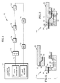
- an optical safety chain 10 in accordance with the present invention utilizing optical fiber 12 comprises a plurality of hoistway door locks 14, a car door lock 15, and an elevator controller 17 having a light transmitter 18 and a light receiver 19.
- the elevator controller 17 is positioned in the machine room of the elevator system (not shown).
- each of a plurality of hoistway door locks 14 using optical fiber 12 comprises a lock mechanism 22 and a hoistway lock housing 24.
- a mechanism passageway 36 is disposed within the lock mechanism 22.
- the mechanism passageway 36 has a first mechanism passageway end 38 oppositely located from a second mechanism passageway end 40.
- Optical fiber 12 is disposed in the mechanism passageway 36.
- Hoistway lock housing 24 includes a first side 26 having a first housing passageway 42, a second side 28 having a second housing passageway 44, a recess 30 and an inner surface 32.
- the inner surface 32 has a curved top edge 34 to facilitate self-guidance of the lock mechanism 22 into the recess 30.
- Optical fiber 12 is disposed within the first housing passageway 42 and the second housing passageway 44.
- the lock mechanism 22 when moving into the engaged position, will rotate downward into the inner recess 30 of hoistway lock housing 24. Referring to FIG. 3, when the lock mechanism 22 is fully rotated, the first mechanism passageway end 38 is in register with first housing passageway 42. Also, second mechanism passageway end 40 is in register with second housing passageway 44.
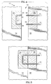
- the car door lock 15 comprises a car door lock housing 50 having a first portion 52 mounted on an elevator car door 54 and a second portion 56 mounted on an elevator car door 58 adjacent to elevator car door 54.
- First portion 52 includes a first car passageway 60 having a first passageway end 62 and a second passageway end 64.
- Second portion 56 includes a second car passageway 66 and a third car passageway 68 protruding therefrom.
- the car door lock 15 also has optical fiber 12 disposed within the first car passageway 60, second car passageway 66, and third car passageway 68. Referring to FIG. 5, as the elevator doors 54, 58 are closed, the second car passageway 66 will align with the first passageway end 62 and the third car passageway 68 will align with the second passageway end 64.
- the optical safety chain 10 includes the plurality of hoistway door locks 14 in series with a car door lock 15.
- a beam of light is originated at the light transmitter 18 located in the elevator controller 17.
- the beam encounters each lock in the series of locks 14, 15, if the lock 14, 15 is mechanically disengaged, the light beam is broken and does not reach the light receiver 19 located in the elevator controller 17 as best seen in FIG. 1.
- the lock is a car door lock 15 and the car door lock 15 is mechanically engaged, the beam of light is transmitted through the car door lock housing 50.
- the lock is a hoistway door lock 14 and the hoistway door lock 14 is mechanically engaged, the beam of light is transmitted from one of the first or second sides 26, 28 of the hoistway lock housing 24, through the lock mechanism 22, to the other of the first or second sides 26, 28 of hoistway lock housing 24.
- the beam is continuously transmitted through the safety chain 10, the light will reach the light receiver 19.
- the elevator controller 17 will be signaled by the light receiver 19 that all the locks 14, 15 are engaged and the elevator controller 17 may use this information in management of the optical safety chain 10.
- a plurality of amplifiers 72 may be used in order to correct any loss of light at junctions in the safety chain 10.
- the plurality of amplifiers 72 will ensure that the light receiver 19 will receive the signal that all the locks 14, 15 in the optical safety chain 10 are engaged.
- the preferred embodiment of the present invention uses a single mode optical fiber for the transmission of light throughout the safety chain.
- the preferred embodiment uses a non-linear mechanism passageway 36 to minimize the amount of light passing through the safety chain 10 when the lock is disengaged.
- the first car passageway 60 of the car door lock 15 also has a non-linear shape to minimize the amount of incident light in the safety chain 10.
- the present invention of an optical safety chain using a plurality of optomechanical locks in combination with a controller having a transmitter and receiver, provides a system which can be adopted to provide more reliable detection of mechanical locking.
- One of the unique features of the present invention is that it reduces maintenance costs by eliminating cleaning of electrical contacts and eliminating engineering calls due to "false" locking.
- the preferred embodiment of the present invention uses a single mode fiber, a multi mode fiber may be used in the present invention to differentiate, for example, hoistway door locks from the car door lock. Also the preferred embodiment uses a non-linear passageway in the lock mechanism of the hoistway door lock and in the lock housing of the car door lock. However, linear passageways may be used in the present invention.
Landscapes
- Elevator Door Apparatuses (AREA)
Applications Claiming Priority (2)
| Application Number | Priority Date | Filing Date | Title |
|---|---|---|---|
| US911871 | 1997-08-15 | ||
| US08/911,871 US5950767A (en) | 1997-08-15 | 1997-08-15 | Optical door lock |
Publications (3)
| Publication Number | Publication Date |
|---|---|
| EP0897892A2 true EP0897892A2 (de) | 1999-02-24 |
| EP0897892A3 EP0897892A3 (de) | 2001-05-30 |
| EP0897892B1 EP0897892B1 (de) | 2005-10-26 |
Family
ID=25431023
Family Applications (1)
| Application Number | Title | Priority Date | Filing Date |
|---|---|---|---|
| EP98306537A Expired - Lifetime EP0897892B1 (de) | 1997-08-15 | 1998-08-17 | Optische Türverriegelung |
Country Status (3)
| Country | Link |
|---|---|
| US (1) | US5950767A (de) |
| EP (1) | EP0897892B1 (de) |
| DE (1) | DE69832013T2 (de) |
Cited By (5)
| Publication number | Priority date | Publication date | Assignee | Title |
|---|---|---|---|---|
| US6382362B1 (en) | 2001-02-13 | 2002-05-07 | Inventio Ag | Optical monitoring system for hoistway door interlocks |
| US6945363B2 (en) * | 2002-05-03 | 2005-09-20 | Inventio Ag | Method of contactlessly monitoring elevator shaft doors |
| EP1795486A4 (de) * | 2004-09-27 | 2011-08-10 | Mitsubishi Electric Corp | Verriegelungsvorrichtung für aufzug |
| WO2014023876A1 (en) * | 2012-08-07 | 2014-02-13 | Kone Corporation | Safety circuit and elevator system |
| WO2016066361A1 (de) * | 2014-10-30 | 2016-05-06 | Robert Bosch Gmbh | Schalter und sicherungssystem zur überwachung eines zulässigen arbeitsbetriebes einer maschine oder einer vorrichtung |
Families Citing this family (6)
| Publication number | Priority date | Publication date | Assignee | Title |
|---|---|---|---|---|
| EP1541515A3 (de) * | 2003-12-08 | 2009-10-28 | Inventio Ag | Aufzug mit optischer Steuervorrichtung |
| US7380641B2 (en) * | 2003-12-08 | 2008-06-03 | Inventio Ag | Elevator with a control using optical fibers |
| EP2567928B1 (de) * | 2011-09-06 | 2013-09-11 | Cedes AG | Sensor, Sicherungsvorrichtung sowie Aufzugvorrichtung |
| US10227208B2 (en) * | 2011-12-12 | 2019-03-12 | Cedes Ag | Safety apparatus for an elevator |
| US11577932B2 (en) * | 2018-07-26 | 2023-02-14 | Otis Elevator Company | Elevator component inspection systems |
| DE102019102004B3 (de) * | 2019-01-28 | 2020-06-10 | Pilz Gmbh & Co. Kg | Verbessertes Zugangsabsicherungssystem zum Absichern einer Maschine oder Anlage |
Family Cites Families (9)
| Publication number | Priority date | Publication date | Assignee | Title |
|---|---|---|---|---|
| BE563315A (de) * | ||||
| DE550716C (de) * | 1932-05-14 | Siemens Schuckertwerke Akt Ges | Tuerkontakt, insbesondere fuer Aufzuege | |
| SE7812688L (sv) * | 1978-12-11 | 1980-06-12 | Stendals El Ab | Indikeringsanordning for takskjutportar |
| EP0035979B1 (de) * | 1980-03-11 | 1984-07-11 | Soc. F.A.M.A. di Sandra Borgato & CO.S.n.c. | Von Hand und elektrisch betriebener selbsttätiger Hakenverschluss |
| US4613176A (en) * | 1983-06-29 | 1986-09-23 | Reliable Security Systems, Inc. | Door latch mechanism |
| GB2212548B (en) * | 1987-11-17 | 1991-12-18 | Walter Wilson Hugh Clarke | Electric locking device |
| DE4112626A1 (de) * | 1991-04-18 | 1992-10-22 | Fraunhofer Ges Forschung | Ueberwachungseinrichtung fuer eine steuervorrichtung |
| CA2132152C (en) * | 1993-10-06 | 2005-02-15 | Peter Spiess | Door safety circuit for the monitoring of storey doors in lift installations |
| US5454447A (en) * | 1994-04-06 | 1995-10-03 | Otis Elevator Company | Elevator hoistway door bolt lock |
-
1997
- 1997-08-15 US US08/911,871 patent/US5950767A/en not_active Expired - Lifetime
-
1998
- 1998-08-17 EP EP98306537A patent/EP0897892B1/de not_active Expired - Lifetime
- 1998-08-17 DE DE69832013T patent/DE69832013T2/de not_active Expired - Lifetime
Cited By (8)
| Publication number | Priority date | Publication date | Assignee | Title |
|---|---|---|---|---|
| US6382362B1 (en) | 2001-02-13 | 2002-05-07 | Inventio Ag | Optical monitoring system for hoistway door interlocks |
| WO2002064477A3 (en) * | 2001-02-13 | 2002-10-10 | Inventio Ag | Optical monitoring system for hoistway information |
| US6945363B2 (en) * | 2002-05-03 | 2005-09-20 | Inventio Ag | Method of contactlessly monitoring elevator shaft doors |
| EP1795486A4 (de) * | 2004-09-27 | 2011-08-10 | Mitsubishi Electric Corp | Verriegelungsvorrichtung für aufzug |
| WO2014023876A1 (en) * | 2012-08-07 | 2014-02-13 | Kone Corporation | Safety circuit and elevator system |
| US10011459B2 (en) | 2012-08-07 | 2018-07-03 | Kone Corporation | Safety circuit and elevator system with optical cable |
| EA034997B1 (ru) * | 2012-08-07 | 2020-04-15 | Коне Корпорейшн | Схема безопасности и лифтовая система |
| WO2016066361A1 (de) * | 2014-10-30 | 2016-05-06 | Robert Bosch Gmbh | Schalter und sicherungssystem zur überwachung eines zulässigen arbeitsbetriebes einer maschine oder einer vorrichtung |
Also Published As
| Publication number | Publication date |
|---|---|
| EP0897892B1 (de) | 2005-10-26 |
| DE69832013T2 (de) | 2006-07-13 |
| DE69832013D1 (de) | 2005-12-01 |
| EP0897892A3 (de) | 2001-05-30 |
| US5950767A (en) | 1999-09-14 |
Similar Documents
| Publication | Publication Date | Title |
|---|---|---|
| US5950767A (en) | Optical door lock | |
| RU2292297C2 (ru) | Защитный контур для дверей лифта | |
| US11795033B2 (en) | Elevator car door interlock | |
| CN100522786C (zh) | 电梯设备、竖井门监视系统和竖井门栓锁 | |
| US20100270109A1 (en) | Control strategy for operating two elevator cars in a single hoistway | |
| EP0839754B1 (de) | Überwachung eines handbetriebenen Aufzugstürsystems | |
| US20240034593A1 (en) | Elevator, method for controlling an elevator | |
| US6382362B1 (en) | Optical monitoring system for hoistway door interlocks | |
| US5899302A (en) | Elevator door interlock | |
| EP0557861A2 (de) | Fernüberwachungseinrichtung für Sicherheitstüre und dergleichen | |
| JP2021181299A (ja) | ホームドア制御システム | |
| US20080271958A1 (en) | Elevator Door Lock | |
| EP1418149B1 (de) | Aufzugstürensicherheitseinrichtung | |
| KR870001468B1 (ko) | 경보 장치 | |
| US7063189B2 (en) | Method and apparatus for a scanning an elevator entry way | |
| EP1377720B1 (de) | Zuhaltungsschloss | |
| EP1795486A1 (de) | Verriegelungsvorrichtung für aufzug | |
| JP2002316782A (ja) | エレベータ扉システムの扉監視装置 | |
| CN117098719A (zh) | 电梯设备和电梯门控制方法 | |
| KR20250088154A (ko) | 엘리베이터 카 위치추적 시스템 | |
| IT1277921B1 (it) | Dispositivo di ritegno di sicurezza per porte di ascensori o pozzi di ascensori | |
| JPH10316338A (ja) | 自動開閉扉の安全装置 | |
| JPH09199754A (ja) | 物体検知装置 | |
| JPH05284635A (ja) | 開閉器の予防保全システム及び開閉器 | |
| HK1066781B (en) | Safety circuit for elevator doors |
Legal Events
| Date | Code | Title | Description |
|---|---|---|---|
| PUAI | Public reference made under article 153(3) epc to a published international application that has entered the european phase |
Free format text: ORIGINAL CODE: 0009012 |
|
| AK | Designated contracting states |
Kind code of ref document: A2 Designated state(s): DE FR GB |
|
| AX | Request for extension of the european patent |
Free format text: AL;LT;LV;MK;RO;SI |
|
| PUAL | Search report despatched |
Free format text: ORIGINAL CODE: 0009013 |
|
| AK | Designated contracting states |
Kind code of ref document: A3 Designated state(s): AT BE CH CY DE DK ES FI FR GB GR IE IT LI LU MC NL PT SE |
|
| AX | Request for extension of the european patent |
Free format text: AL;LT;LV;MK;RO;SI |
|
| 17P | Request for examination filed |
Effective date: 20010713 |
|
| AKX | Designation fees paid |
Free format text: DE FR GB |
|
| 17Q | First examination report despatched |
Effective date: 20040325 |
|
| GRAP | Despatch of communication of intention to grant a patent |
Free format text: ORIGINAL CODE: EPIDOSNIGR1 |
|
| GRAS | Grant fee paid |
Free format text: ORIGINAL CODE: EPIDOSNIGR3 |
|
| GRAA | (expected) grant |
Free format text: ORIGINAL CODE: 0009210 |
|
| AK | Designated contracting states |
Kind code of ref document: B1 Designated state(s): DE FR GB |
|
| REG | Reference to a national code |
Ref country code: GB Ref legal event code: FG4D |
|
| REF | Corresponds to: |
Ref document number: 69832013 Country of ref document: DE Date of ref document: 20051201 Kind code of ref document: P |
|
| ET | Fr: translation filed | ||
| PLBE | No opposition filed within time limit |
Free format text: ORIGINAL CODE: 0009261 |
|
| STAA | Information on the status of an ep patent application or granted ep patent |
Free format text: STATUS: NO OPPOSITION FILED WITHIN TIME LIMIT |
|
| 26N | No opposition filed |
Effective date: 20060727 |
|
| PGFP | Annual fee paid to national office [announced via postgrant information from national office to epo] |
Ref country code: GB Payment date: 20070705 Year of fee payment: 10 |
|
| PGFP | Annual fee paid to national office [announced via postgrant information from national office to epo] |
Ref country code: FR Payment date: 20070803 Year of fee payment: 10 |
|
| GBPC | Gb: european patent ceased through non-payment of renewal fee |
Effective date: 20080817 |
|
| REG | Reference to a national code |
Ref country code: FR Ref legal event code: ST Effective date: 20090430 |
|
| PG25 | Lapsed in a contracting state [announced via postgrant information from national office to epo] |
Ref country code: FR Free format text: LAPSE BECAUSE OF NON-PAYMENT OF DUE FEES Effective date: 20080901 |
|
| PG25 | Lapsed in a contracting state [announced via postgrant information from national office to epo] |
Ref country code: GB Free format text: LAPSE BECAUSE OF NON-PAYMENT OF DUE FEES Effective date: 20080817 |
|
| PGFP | Annual fee paid to national office [announced via postgrant information from national office to epo] |
Ref country code: DE Payment date: 20120816 Year of fee payment: 15 |
|
| PG25 | Lapsed in a contracting state [announced via postgrant information from national office to epo] |
Ref country code: DE Free format text: LAPSE BECAUSE OF NON-PAYMENT OF DUE FEES Effective date: 20140301 |
|
| REG | Reference to a national code |
Ref country code: DE Ref legal event code: R119 Ref document number: 69832013 Country of ref document: DE Effective date: 20140301 |