EP0898879A2 - Dispositif pour contrÔler une fonction par programme - Google Patents
Dispositif pour contrÔler une fonction par programme Download PDFInfo
- Publication number
- EP0898879A2 EP0898879A2 EP98115970A EP98115970A EP0898879A2 EP 0898879 A2 EP0898879 A2 EP 0898879A2 EP 98115970 A EP98115970 A EP 98115970A EP 98115970 A EP98115970 A EP 98115970A EP 0898879 A2 EP0898879 A2 EP 0898879A2
- Authority
- EP
- European Patent Office
- Prior art keywords
- unit
- control unit
- programming
- control
- contact means
- Prior art date
- Legal status (The legal status is an assumption and is not a legal conclusion. Google has not performed a legal analysis and makes no representation as to the accuracy of the status listed.)
- Granted
Links
- 238000007789 sealing Methods 0.000 claims description 15
- 238000013459 approach Methods 0.000 claims description 13
- 239000007788 liquid Substances 0.000 claims description 13
- 230000000295 complement effect Effects 0.000 claims description 9
- 230000002262 irrigation Effects 0.000 claims description 8
- 238000003973 irrigation Methods 0.000 claims description 8
- 150000001875 compounds Chemical class 0.000 claims description 6
- 238000003780 insertion Methods 0.000 claims description 4
- 230000037431 insertion Effects 0.000 claims description 4
- 238000004382 potting Methods 0.000 claims description 4
- XLYOFNOQVPJJNP-UHFFFAOYSA-N water Substances O XLYOFNOQVPJJNP-UHFFFAOYSA-N 0.000 claims description 4
- 230000003993 interaction Effects 0.000 claims description 3
- 230000013011 mating Effects 0.000 claims description 3
- 210000002105 tongue Anatomy 0.000 claims description 3
- 239000004020 conductor Substances 0.000 description 3
- 238000004519 manufacturing process Methods 0.000 description 3
- 230000005540 biological transmission Effects 0.000 description 2
- 230000002950 deficient Effects 0.000 description 2
- 238000012423 maintenance Methods 0.000 description 2
- 230000005226 mechanical processes and functions Effects 0.000 description 2
- 230000008672 reprogramming Effects 0.000 description 2
- 239000002689 soil Substances 0.000 description 2
- HUWSZNZAROKDRZ-RRLWZMAJSA-N (3r,4r)-3-azaniumyl-5-[[(2s,3r)-1-[(2s)-2,3-dicarboxypyrrolidin-1-yl]-3-methyl-1-oxopentan-2-yl]amino]-5-oxo-4-sulfanylpentane-1-sulfonate Chemical compound OS(=O)(=O)CC[C@@H](N)[C@@H](S)C(=O)N[C@@H]([C@H](C)CC)C(=O)N1CCC(C(O)=O)[C@H]1C(O)=O HUWSZNZAROKDRZ-RRLWZMAJSA-N 0.000 description 1
- 230000006978 adaptation Effects 0.000 description 1
- 230000000712 assembly Effects 0.000 description 1
- 238000000429 assembly Methods 0.000 description 1
- 230000000903 blocking effect Effects 0.000 description 1
- 238000005266 casting Methods 0.000 description 1
- 238000011161 development Methods 0.000 description 1
- 230000018109 developmental process Effects 0.000 description 1
- 238000009826 distribution Methods 0.000 description 1
- 230000007613 environmental effect Effects 0.000 description 1
- 238000011990 functional testing Methods 0.000 description 1
- 239000012535 impurity Substances 0.000 description 1
- 238000002347 injection Methods 0.000 description 1
- 239000007924 injection Substances 0.000 description 1
- 238000009434 installation Methods 0.000 description 1
- 239000000463 material Substances 0.000 description 1
- 230000003647 oxidation Effects 0.000 description 1
- 238000007254 oxidation reaction Methods 0.000 description 1
- 230000000149 penetrating effect Effects 0.000 description 1
- 230000002441 reversible effect Effects 0.000 description 1
- 230000008054 signal transmission Effects 0.000 description 1
- 230000011664 signaling Effects 0.000 description 1
- 230000006641 stabilisation Effects 0.000 description 1
- 238000011105 stabilization Methods 0.000 description 1
Images
Classifications
-
- A—HUMAN NECESSITIES
- A01—AGRICULTURE; FORESTRY; ANIMAL HUSBANDRY; HUNTING; TRAPPING; FISHING
- A01G—HORTICULTURE; CULTIVATION OF VEGETABLES, FLOWERS, RICE, FRUIT, VINES, HOPS OR SEAWEED; FORESTRY; WATERING
- A01G25/00—Watering gardens, fields, sports grounds or the like
- A01G25/16—Control of watering
Definitions
- the invention relates to a device for program-controlled Execution of a function, in particular a program-controlled one Valve for controlling a liquid flow in a water pipe of a garden irrigation system.
- Generic devices carry one or more mechanical Functions that, in particular, according to a specifiable Time program can run.
- Typical application examples in the area of house and garden irrigation are program-controlled Irrigation devices or program-controlled Shut-off and / or distribution valves used in liquid lines and / or liquid line networks are provided are.
- a generic device has a means a programmable electronic programmable device Control for the delivery of electrical control signals and a controlled by the control signals, preferably electrically operable device for performing the function.
- a generic type known from US Pat. No. 4,108,419 Device is a valve of an automatic irrigation system.
- the control of the valve and that for programming programming device provided to the control are in a removable from the actual valve housing Housing head housed, in which the batteries for electrical power supply of the programming and control unit are accommodated.
- On the removable housing head are rotary switches for manual setting of the desired one Irrigation time program provided.
- the one from the valve body removable control and programming unit is relative heavy and large and because of their complex structure in expensive to manufacture. The number of over the knobs selectable, embodied in an electronic circuit Programs is limited.
- the invention has for its object a generic To create device that is economical to manufacture and can be used variably with only a small amount of operation.
- the device should also be easy to maintain and repair and / or it should be a simple, location-independent Programming, for example at the location of an Garden fixed functional unit can be enabled.
- the invention proposes a device with the features of claim 1.
- control is assigned to a control unit, which may consist solely of the controller can, but usually other functional parts, however contains no programming device.
- the control unit is mechanically and electrically detachable with a device having functional unit connectable.
- the functional unit can essentially only be controlled Facility include, but usually contains more functional parts.
- the programming device is one assigned separate programming unit, the mechanical and is electrically releasably connectable to the control unit and which is preferably also separate from the functional unit.
- the device according to the invention has a modular structure.
- the interacting modules, i.e. the control unit, the programming unit and the functional unit can in particular completely electrically and mechanically separated become.
- the controller programmable by the programming unit the control unit can advantageously be used with a variety of different Functional units are used.
- the control unit can e.g. removed from a liquid valve and, if necessary after reprogramming, to control a pump, garden lighting, balcony watering or as Switch replacement used on a wall or the like become.
- the same programming unit can be used for programming be used.
- the functional unit can, for example, be in a liquid line include a fixed or detachable valve.
- the functional unit remains at its functional location practical for valves permanently connected to a line system inevitable. Even with a detachable connection, it should but can only be solved in exceptional cases, otherwise under Circumference problems when restoring the connection may occur.
- In an inventive Device can be the functional unit on the line system remain while the control unit is removed and possibly repaired or reprogrammed far from the functional unit or, if necessary, exchanged for another control unit can be. Reprogramming can be advantageous simply by replacing a controller with one after another other program working control, what for example when changing to a newer version of a controller or a program is an advantage.
- the functional unit and the programming unit can continue to be used unchanged become.
- control unit is the programmable controller, but not the one intended for their programming Contains programming device, it can be very inexpensive be made and be light and compact. A possibly necessary Replacement of a defective control does not record the programming device, which for example for the sake of Economy and environmental protection is an advantage.
- control unit without tools, i.e. without the use of tools such as screwdrivers or the like, with the functional unit and / or connectable to the programming unit and / or without tools from this is solvable.
- the operating effort when removing or attaching the control unit on the functional unit and / or the programming unit particularly low.
- the control unit can preferably be on or in the functional unit and / or the programming unit can be clamped. You can do this on the functional unit or the programming unit and / or separate cooperating on the control unit Clamping devices may be provided.
- the Control unit and the functional unit and / or the programming unit themselves trained so that they meet each other can be clamped, in particular can be plugged together.
- It can have at least one elastic element for non-positive Holder of the control unit on the functional unit and / or the programming unit may be provided, preferably a elastically compressible sealing element such as a Plastic o-ring can be.
- the mechanical connection of the Modules can only be connected by a positive connection, for example jamming against pulling apart of the components are effected.
- the control unit with the functional unit and / or the programming unit be positively connectable, for example by clamps or screws.
- a positive connection can reliably prevent accidental loosening of control unit and prevent functional unit or programming unit.
- control unit a the control is liquid-tight at least in some areas covering housing, which is preferably made of Plastic is made.
- the housing can be in several parts and in particular two releasably connectable, preferably have screwed housing parts.
- the housing or the housing parts can be injection molded be.
- a control that at least partially encloses the control Housing can largely prevent this from damage protect.
- the control can due to the mechanical connection of the housing parts Housing are fixed, creating separate fasteners for control in the housing can be omitted.
- the control can be sealed moisture-proof at least in some areas be, the controller preferably as a printed circuit board is formed with electronic components that are surrounded by a moisture-proof sealing compound.
- the potting compound can the side of the circuit board equipped with the components preferably cover completely and, if necessary, the opposite side with conductor tracks for contacting set free. One firmly in contact with the circuit board standing layer of potting material stabilizes the PCB mechanically.
- the control device can have at least one actuator have to manually switch the control, for example a valve from a blocking position to a open position and can be switched back. It is also possible one or more actuators in such a way with the To couple circuit that over the actuators Control program is turned on or off and / or that can be switched between different control programs can.
- the actuator can via a housing wall of the housing protrude from the control unit.
- An actuator can be designed in particular as a tip switch. Preferably it is sealed so liquid-tight that no liquid in the area of the actuator Housing can penetrate.
- the control To perform the control function, the control must be signal-conducting, in particular electrically conductive with the device get connected.
- the control unit produces first contact means a detachable, signal-conducting electrical first connection the control with the facility.
- the first connection is intended to transmit signal voltages.
- the Establishment is with appropriate complementary contact means equipped to interact with the Control signals transmitting first contact means formed are.
- the first contact means as part of a first electrical Plug connection are formed, the first contact means preferably as part of a preferred bipolar Coaxial connector are formed.
- an inner contact pin is provided by an outer one Contact sleeve is surrounded.
- a coaxial connector for the signal line is particularly insensitive to in particular electromagnetic interference.
- the corresponding contact means the functional unit are complementary. They particularly have one for contacting the Contact pin provided central sleeve and one for Push one into the other provided with the contact sleeve Sleeve on.
- the arrangement of plugs on one and However, there are sockets on the other side of the connector also possible vice versa.
- the first connector causes in addition to the electrical connection also a non-positive connection mechanical connection of the modules, so that if necessary separate mechanical connecting means can be omitted.
- control it is possible for the control to have its own power supply to provide, for example one in the housing of Control unit housed battery.
- the control unit does not have its own electrical embodiment Power supply for the control.
- Such Control unit is particularly compact and inexpensive to manufacture and a possibly necessary replacement of the control unit does not detect the power supply for the control unit.
- the second electrical connection is preferably for the transmission of direct voltages in the volt range designed. It is preferred if the second contact means as part of a second electrical connector are trained.
- the second connector can in particular be two-pin flat connector. Preferably are connected to the control flat sockets, which for Interaction with corresponding flat tabs trained who are in contact with the external power supply stand. Again, the arrangement of plugs on the one and sockets on the other side of the second connector reversible.
- the power supply for the control and / or the functional unit can be separated from the control unit and if necessary be arranged separately from the functional unit.
- the functional unit has a preferably network-independent one own power supply for the facility, in particular comprises at least one accumulator.
- This power supply provides the electrical energy for operation the electrical device to carry out the desired Function available.
- the power supply is preferred an external power supply to the functional unit for the control unit.
- the power supply can be electrically connected to contact means be to interact with the second contact means the control unit are formed. When connecting Control unit and functional unit can via the contact means an electrical connection of the power supply Functional unit to be manufactured for control.
- An external programming device only has to be used for programming connected to the controller and can be used during the normal operation of the device separately from this stored or possibly for programming other controls be used. It is possible to use the programming device via a specially designed for programming to connect the electrical connection to the control.
- electrical contact means that interact with the first contact means of the control unit are formed, especially as part of a coaxial connector. This Contact means are with the signaling electronics of the Programming device connected. This makes it possible to Contact that is in operation of the device for the transmission of Signals used between the control unit and functional unit will also be used for programming.
- a separate connection to the control unit, which may be separate should be sealed, can therefore be omitted.
- the means of contact the programming unit can be connected to the Programming unit connectable cables are provided however, preferably directly on a housing of the programming unit intended.
- a preferred programming unit preferably has one independent power supply, preferably comprises at least one accumulator.
- the power supply the program unit can advantageously be electrically with contact means be connected to cooperate with the second Contact means of the control unit are formed, in particular Flat tabs.
- Such an execution enables it, the power supply to the programming unit as Power supply to use the control unit, in particular when programming the control.
- the electrical Connection of the electrical contacts of the programming device with those of the control unit can be done via cable. However, it is preferably wireless.
- the programming unit be designed such that it is mechanical and can be electrically detachably connected to the control unit, is particularly pluggable. It can at the same time as a holder for the control unit during programming Act.
- the programming device preferably has a programmer contact arrangement, which is essentially the functional unit contact arrangement corresponds so that the control device in the same Way to both the functional unit and the programming device can be connected electrically.
- Any programming device per se can be used for programming be provided because the programming is not on Location of the functional unit must be made. It can for example, a fixed programming device is provided be used for programming under Use of a computer can be done.
- the programming unit as a portable, preferably hand-held Programming device trained. It can be hollow Have handle in which, for example, batteries or Accumulators for supplying power to the programming unit and possibly one connected to the programming unit Control unit are provided.
- a portable programming device can program the control unit be carried out directly at the place of use of the device by only the control unit from the functional unit removed and connected to the programming device or coupled and on again after completing programming the functional unit is connected or coupled.
- first electrical connection and the second electrical connection by a single relative movement of the Control unit relative to the functional unit or to the programming unit releasable in a common connection direction or is producible.
- the first and the second contact means are thereby essentially simultaneously with the corresponding ones Contact means of the functional unit or programming unit electrically connected.
- the thru axles of the first and the second connector substantially parallel.
- the first electrical connection and / or the second electrical connection in the connected state of control unit and functional unit and preferably also then when control unit and programming unit are connected are sealed liquid-tight.
- the sealing device can preferably an elastically compressible sealing element, such as have an O-ring, which in addition to the sealing function a function in the context of a non-positive holder of the Control unit on the functional unit or on the programming unit exercises.
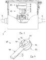
- FIG. 1 shows one through an essentially box-shaped plastic housing formed, closable by means of a hinged lid Shaft 1, which in particular also for partial or almost completely submerged in the soil suitable and determined is.
- the shaft can be connected via pipe connections that are parallel to the axis 2 on preferably slightly elastic plastic pipes a preferably underground water supply network be connected.
- a shaft of the type shown and its uses are for example in the German patent DE 39 24 795. Im limited by the housing walls Inside the shaft runs a connecting pieces 2 connecting Plastic pipe section 3, on the middle between the connectors an electromagnetically actuated to Interrupting the liquid flow provided in the pipe section 3 Shut-off valve 4 is screwed on.
- an electromagnet 5 is provided which is electrically connected to a not shown electrical power supply connected which includes an accumulator and which in one the valve 4 and the electromagnet 5 enclosing plastic housing 6 is housed.
- the electromagnetically switchable shut-off valve 4 forms one in the liquid flow of the pipe section 3 intervening device for executing a mechanical function, namely opening and closing a liquid passage. Together with the electromagnet and the power supply it forms a functional unit 10, also as a solenoid valve assembly or as a solenoid valve assembly referred to as.
- the functional unit 10 On top of a pot-shaped one, essentially cylindrical extension 11 the functional unit 10 is liquid-tight in the manner of a sealed power cord plug a completely electric and mechanically detachable control unit 15 attached.
- the hinged cover of the valve shaft is opened.
- closed state of the hinged lid lies there flat underside at a short distance above the flat top of the control unit 15, so that a loosening of the Control unit from the functional unit is not possible.
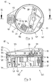
- in the 1 shown assembled state of the control unit and functional unit is that in FIGS. 2 and 3 shown interior of the control unit by a better in Fig. 3 Recognizable, essentially closed housing at the top 16 and by a cylindrical outer circumference Approach 17 of the control unit circumferential sealing ring 18, the presses against the cylindrical inside of the neck 11, completely sealed against external moisture.
- the control unit has a two-part plastic housing 16, that by one in Fig. 3 open downwards, one-sided beveled housing cover 19 and one by screws 20 screwed adapter 21 is formed, which can be plugged together with the cylindrical extension 11 of the functional unit 10 is provided. Between the two housing parts 19, 21, a circuit board 22 is clamped on the Housing cover 19 facing away from electronic components, not shown are attached. Through the through conductor tracks connected electronic components is the externally programmable Control unit 23 embodies the control unit.
- the electronic elements are for protection against moisture with a Layer 24 made of a moisture-proof plastic casting compound covered, which encloses the components and at the same time to mechanical stabilization of the circuit board arrangement contributes.
- the circuit board arrangement 22, 24 is during installation into the control unit on a rotating, step-shaped, inward projection 25 of the housing cover 19th placed and by screwing the one front projection 26 having adaptation part 21 fixed in position between Housing cover 19 and adapter 21 clamped.
- the control is therefore not a separate fastener, such as screws or the like.
- a The control can be replaced in a simple manner Unscrew the two housing parts 19, 21, take them out the controller 23 and replace it with another controller.
- a contact for manual in the embodiment shown Actuation of the control provided via a tip switch 27 can be operated.
- the tip switch 27 is than the top of the cover 19 slightly superior Rubber button formed on which an elastic cone 28 with an annular foot 29 which is approximately square in cross section is trained.
- the foot 29 is in the assembled state the housing parts by an annular extension 30 of the housing cover sealingly pressed onto the top of the circuit board and seals the contact point moisture-proof.
- the controller 23 can be operated manually via the actuator 27 are switched, for example to switch between a closed position and an open position of the shut-off valve 4.
- the tip switch 27 is with the lid open Easily accessible shaft.
- the electrical contacting of the on the printed circuit board 22nd housed electronic control 23 takes place essentially via two separate plug contact groups, which with the conductor tracks of the circuit board electrically connected are.
- the plug contacts are through the potting compound layer 24 held and protrude from the sealing compound side facing away from the cover. They are first electrical Contact means 35 for producing a detachable, signal-conducting first connection of the controller with complementary Contact means of the functional unit and preferably one Programming unit described later provided.
- right-angled contact foot 36 protrudes a cylindrical, metallic Contact sleeve 37 out, which is a little shorter axially surrounds round metallic contact pin 38.
- the coaxial connector 35 is used for the signal-conducting transmission of control signals from the controller 23 to that through the control signals controlled solenoid valve 4 when control unit 15 and functional unit 10 are put together. He continues to serve the signal-conducting electrical connection to a programming device, with which is embodied in the controller 23 Control program for the valve can be changed if necessary can.
- the control unit does not have its own electrical power supply for control.
- For connecting an external Power supply are in contact with the controller 23 standing second contact means protruding from the sealing compound 40 provided as sockets of a two-pole Flat plug contact are formed.
- the thru axles of the Coaxial connector 35 and the flat socket 40 are parallel, so that both electrical connections through a common Plug-in movement made parallel to the plug-in axles or can be solved.
- the functional unit 10 has with the Flat sockets 40 cooperating flat tongues, the electrical with the power supply of the functional unit are connected so that the power supply of the functional unit at the same time the power supply of the Control unit is when it is plugged onto the functional unit is. Because the control unit does not have its own electrical Power supply, it can be particularly light and can be manufactured inexpensively.
- the first contact means 35 and the spring-loaded second Contact means 40 of the control unit form a control unit contact arrangement, the one with an essentially mirror image arranged complementary functional unit contact arrangement cooperates.
- the electrical contact the plug connections alone can be enough Control unit and the functional unit also non-positively connect mechanically.
- the when making the plug contacts contact surfaces sliding against each other and rubbing against each other additionally cleanse themselves of each other Impurities, such as oxidation films, so that A good electric one at all times, even in a damp environment signal conducting and supply current conducting electrical Contact between control unit and functional unit guaranteed is.
- a detachable mechanical connection between the control unit and functional unit is continued through the forms of interlocking housing of control unit 15 and functional unit 10 created.
- the cylindrical approach 17 of the Adaption part 21 has an essentially cylindrical for this purpose Outside 41, the outside diameter of the inside diameter corresponds to the cylindrical extension 11 of the functional unit.
- control unit For a complete liquid-tight seal when plugged together, the control unit one around the neck 17 in a circumferential, semicircular Groove 42 lying sealing ring 18, when plugging together of control unit and functional unit to the inside of the Approach 11 is pressed and so the contact space is liquid-tight seals.
- the compressible sealing ring 18 promotes at the same time a positive mechanical connection between control unit and functional unit against pulling apart of components 10, 15.
- a two-pole socket 44 arranged, even in the assembled state is accessible from the control unit and functional unit.
- the Contacts 44 are connected to the controller 23 and serve the optional connection of an externally attachable moisture sensor. This can, for example, after extensive Give a signal to the controller in the event of rain, with which the Program run of a sprinkler interrupted and will be resumed later.
- the described embodiment of the invention is that in 4 assigned to the programming unit 45 shown schematically.
- the programming unit is as a portable, hand-held Programming device trained. This has one through two with each other screw-formed plastic housing shells 46, 47 formed Housing on which an internally hollow handle 48 is formed is. Inside the handle you can at least an accumulator or at least one battery for electrical Power supply to the programming device is provided be. 4 at the upper end of the handle 48 an essentially cylindrical housing head 49 is formed, whose axis is substantially perpendicular to the longitudinal axis of the Handle 48 runs.
- One for the operator when using facing flat back 50 of the housing head carries one Group of controls 51, in the example as liquid-tight push buttons sealed against the housing are.
- the status of the device is via an LCD display panel readable.
- the programming device has electrical contacts in a programming unit contact arrangement that the Functional unit contact arrangement corresponds. This can the control unit in one and the same way by plugging both with the functional unit 10 and with the programming unit 45 releasably electrically connected. Programming the control leads to programming Control signals provided by the housed in the housing 46, 47 Programming electronics via the first contact means 35 of the control device for control 23. At the same time the power supply accommodated in the handle 48 with the plug contacts 40 corresponding tongues electrically connected to the controller 23 so that the power supply the programming unit at the same time external power supply for the controller 23 of the control unit 15 is.
- the programming unit contact arrangement is by a cylindrical projection formed on the housing part 47 54 enclosed, the inside of which has the same shape and Dimension as the inside of the approach 11 has. Thereby are in contact with each other during programming standing electrical contacts through the seal 18 on the Control unit sealed against moisture from the outside.
- the contact areas of the programming device are therefore an advantage and solenoid valve in the embodiment shown at least identical in terms of electrical contact arrangements. This is compared to a separate one that is also possible Contacting the energy supply contacts on the one hand and the signal contacts on the other hand in the programming state advantageous because of the much easier handling.
- a preferred embodiment of the invention thus provides not only the unit of control electronics and functional unit, especially electromagnetic valve divide into one containing the functional device Assembly and a control electronics assembly releasably connected to it. It also becomes the previous unit of programming electronics and control electronics divided by in addition to the control electronics module, a separate programming module is provided.
- the electrical connection between the units takes place facing each other Plug contacts of the modules.
- the control electronics assembly is on their facing away from the valve or the programming device Side completely closed and therefore offers no attack for penetrating moisture.
- the mechanical connection of the circumferential seal supporting the assemblies protects the electrical contacts against moisture and simultaneously supports the frictional mechanical Connection of control unit and functional unit and preferably also of control unit and programming unit.
Landscapes
- Engineering & Computer Science (AREA)
- Water Supply & Treatment (AREA)
- Life Sciences & Earth Sciences (AREA)
- Environmental Sciences (AREA)
- Domestic Plumbing Installations (AREA)
- Fluid-Pressure Circuits (AREA)
- Flow Control (AREA)
- Push-Button Switches (AREA)
Applications Claiming Priority (2)
| Application Number | Priority Date | Filing Date | Title |
|---|---|---|---|
| DE19737721 | 1997-08-29 | ||
| DE19737721A DE19737721A1 (de) | 1997-08-29 | 1997-08-29 | Vorrichtung zur programmgesteuerten Ausführung einer Funktion |
Publications (3)
| Publication Number | Publication Date |
|---|---|
| EP0898879A2 true EP0898879A2 (fr) | 1999-03-03 |
| EP0898879A3 EP0898879A3 (fr) | 1999-10-27 |
| EP0898879B1 EP0898879B1 (fr) | 2003-05-02 |
Family
ID=7840584
Family Applications (1)
| Application Number | Title | Priority Date | Filing Date |
|---|---|---|---|
| EP98115970A Expired - Lifetime EP0898879B1 (fr) | 1997-08-29 | 1998-08-25 | Dispositif pour contrôler une fonction par programme |
Country Status (3)
| Country | Link |
|---|---|
| EP (1) | EP0898879B1 (fr) |
| DE (2) | DE19737721A1 (fr) |
| ES (1) | ES2197400T3 (fr) |
Cited By (4)
| Publication number | Priority date | Publication date | Assignee | Title |
|---|---|---|---|---|
| DE102004038819A1 (de) * | 2004-08-02 | 2006-03-16 | Gardena Manufacturing Gmbh | Steuervorrichtung für eine Flüssigkeitspumpenanordnung |
| WO2008103941A3 (fr) * | 2007-02-23 | 2008-10-16 | Great Stuff Inc | Commande à distance pour système de soupape et de dévidoir à flexible |
| EP2308284A1 (fr) * | 2009-10-12 | 2011-04-13 | Claber S.P.A. | Entraînement programmable et ensemble de commande d'électrovanne, en particulier pour systèmes d'irrigation |
| GB2475530A (en) * | 2009-11-23 | 2011-05-25 | Su-Hua Tai | Control device for multiple sprinkler control valves |
Families Citing this family (3)
| Publication number | Priority date | Publication date | Assignee | Title |
|---|---|---|---|---|
| DE20004747U1 (de) | 2000-03-15 | 2000-06-08 | Festo AG & Co, 73734 Esslingen | Steckerartiges Anschlußteil für eine Ventileinrichtung |
| MXPA05009774A (es) | 2003-03-13 | 2006-03-08 | Great Stuff Inc | Control remoto para operacion de manguera. |
| DE102004024038A1 (de) * | 2004-05-10 | 2005-12-01 | Gardena Manufacturing Gmbh | Programmiereinrichtung und Lesegerät für Bewässerungseinrichtungen |
Citations (3)
| Publication number | Priority date | Publication date | Assignee | Title |
|---|---|---|---|---|
| US4108419A (en) | 1976-03-01 | 1978-08-22 | Clifton J. Burwell | Pilot operated valve |
| EP0236535A1 (fr) | 1986-03-11 | 1987-09-16 | L.R. Nelson Corporation | Interrupteur à minuterie électronique pour l'arrosage de terre |
| DE3924795A1 (de) | 1989-07-27 | 1991-01-31 | Gardena Kress & Kastner Gmbh | Fluid-anschlusseinrichtung |
Family Cites Families (18)
| Publication number | Priority date | Publication date | Assignee | Title |
|---|---|---|---|---|
| US3241767A (en) * | 1962-09-06 | 1966-03-22 | Arthur W Jacobs | Automatic sprinkler control system and components thereof |
| FR2315225A1 (fr) * | 1975-06-24 | 1977-01-21 | Leygonie Alain | Procede et dispositif d'arrosage automatique |
| AU4527585A (en) * | 1984-07-24 | 1986-01-30 | Donaghys Electronics Ltd. | Irrigation diaphragm valve control |
| WO1986005945A1 (fr) * | 1985-04-15 | 1986-10-23 | Townsend Controls Pty. Ltd. | Systeme ameliore de commande d'irrigation |
| WO1986006579A1 (fr) * | 1985-05-16 | 1986-11-20 | Sabco Limited | Systeme d'irrigation |
| US4807664A (en) * | 1986-07-28 | 1989-02-28 | Ansan Industries Ltd. | Programmable flow control valve unit |
| DE3727912A1 (de) * | 1987-08-21 | 1989-03-02 | Congermania Mess & Regel | Mess- oder zaehlgeraet, insbesondere wasserzaehler oder waermemengenzaehler |
| DE3743446A1 (de) * | 1987-12-22 | 1989-07-13 | Graetz Nokia Gmbh | Geraetesystem |
| FR2636205A1 (fr) * | 1988-09-12 | 1990-03-16 | Boulogne Ste Indle | Installation automatique d'arrosage |
| ATE116746T1 (de) * | 1988-10-04 | 1995-01-15 | Solatrol Inc | Zentralverwaltungssystem der bewässerungseinheiten. |
| DE3906134A1 (de) * | 1989-02-28 | 1990-08-30 | Schlueter Electronic | Messwertspeichergeraet |
| DE3933356A1 (de) * | 1989-10-06 | 1991-04-18 | Licentia Gmbh | Elektrizitaetszaehler |
| DE3933689A1 (de) * | 1989-10-09 | 1991-04-11 | Weber Guenther | Gehaeuse |
| DE4025692C2 (de) * | 1990-08-14 | 1995-02-16 | Gardena Kress & Kastner Gmbh | Automatisch steuerbare Ventileinrichtung für eine Wasserleitung |
| DE4029620C2 (de) * | 1990-09-19 | 1995-04-06 | Michael Dipl Ing Schillings | Verfahren und Vorrichtung zum Dosieren von Chargen |
| DE9201368U1 (de) * | 1992-02-05 | 1992-03-26 | SaMeCo Meßtechnik GmbH, 1000 Berlin | Universaladapter für Badewannenzähler |
| DE9201515U1 (de) * | 1992-02-07 | 1993-06-03 | Robert Bosch Gmbh, 7000 Stuttgart | Ventilblock |
| IT236922Y1 (it) * | 1995-05-30 | 2000-08-31 | Claber Spa | Custodia per centralina di irrigazione |
-
1997
- 1997-08-29 DE DE19737721A patent/DE19737721A1/de not_active Withdrawn
-
1998
- 1998-08-25 DE DE59808132T patent/DE59808132D1/de not_active Expired - Lifetime
- 1998-08-25 EP EP98115970A patent/EP0898879B1/fr not_active Expired - Lifetime
- 1998-08-25 ES ES98115970T patent/ES2197400T3/es not_active Expired - Lifetime
Patent Citations (3)
| Publication number | Priority date | Publication date | Assignee | Title |
|---|---|---|---|---|
| US4108419A (en) | 1976-03-01 | 1978-08-22 | Clifton J. Burwell | Pilot operated valve |
| EP0236535A1 (fr) | 1986-03-11 | 1987-09-16 | L.R. Nelson Corporation | Interrupteur à minuterie électronique pour l'arrosage de terre |
| DE3924795A1 (de) | 1989-07-27 | 1991-01-31 | Gardena Kress & Kastner Gmbh | Fluid-anschlusseinrichtung |
Cited By (6)
| Publication number | Priority date | Publication date | Assignee | Title |
|---|---|---|---|---|
| DE102004038819A1 (de) * | 2004-08-02 | 2006-03-16 | Gardena Manufacturing Gmbh | Steuervorrichtung für eine Flüssigkeitspumpenanordnung |
| WO2008103941A3 (fr) * | 2007-02-23 | 2008-10-16 | Great Stuff Inc | Commande à distance pour système de soupape et de dévidoir à flexible |
| US10180204B2 (en) | 2007-02-23 | 2019-01-15 | Great Stuff, Inc. | Remote control for valve and hose reel system |
| EP2308284A1 (fr) * | 2009-10-12 | 2011-04-13 | Claber S.P.A. | Entraînement programmable et ensemble de commande d'électrovanne, en particulier pour systèmes d'irrigation |
| GB2475530A (en) * | 2009-11-23 | 2011-05-25 | Su-Hua Tai | Control device for multiple sprinkler control valves |
| GB2475530B (en) * | 2009-11-23 | 2013-11-27 | Su-Hua Tai | Portable one-to-many control device for a sprinkler pipeline |
Also Published As
| Publication number | Publication date |
|---|---|
| EP0898879B1 (fr) | 2003-05-02 |
| DE19737721A1 (de) | 1999-03-04 |
| EP0898879A3 (fr) | 1999-10-27 |
| ES2197400T3 (es) | 2004-01-01 |
| DE59808132D1 (de) | 2003-06-05 |
Similar Documents
| Publication | Publication Date | Title |
|---|---|---|
| EP0726623A2 (fr) | Dispositif de connexion pour le libre rétablissement d'une connexion électrique réutilisable, par exemple pour le branchement sur des lignes électriques à soins multiples | |
| WO2009059440A1 (fr) | Connecteur et raccord enfichable pour robot | |
| DE102012024588A1 (de) | Autoladestecker | |
| EP3842187B1 (fr) | Dispositif de raccordement d'un câble | |
| DE10334655A1 (de) | Steckverbindervorrichtung für Kleinservomotoren | |
| EP0898879B1 (fr) | Dispositif pour contrôler une fonction par programme | |
| EP1063751A1 (fr) | Unité de pompage | |
| DE102008046932A1 (de) | Gehäuse für eine elektrische Steckverbindung | |
| DE3708902C3 (de) | Steuereinheit für elektrohydraulische Ausbausteuerungen | |
| EP2497173A2 (fr) | Dispositif de réception de composants électriques | |
| DE102007039066B4 (de) | Netzspannungsversorgungsgerät | |
| DE102010046379B4 (de) | Steuereinheit mit Spannungsquelle für eine elektromotorische Möbelantriebseinrichtung | |
| DE3723019C2 (fr) | ||
| EP0757409A1 (fr) | Connecteur électrique | |
| EP1590818B1 (fr) | Dispositif borne de raccordement pour le raccordement d'une cosse de cable de ceinture et appareil electrique correspondant | |
| DE3810886A1 (de) | Kerzenstecker, insbesondere fuer gluehkerzen | |
| DE2645450A1 (de) | Stecksystem fuer stereophoniekanaele | |
| DE102008037738B4 (de) | Elektrische Steckverbindung und elektrisches Gerät | |
| WO2009118032A1 (fr) | Système d'installation électrique de type modulaire | |
| DE2622482C2 (de) | Annäherungsschalter | |
| EP1032005A2 (fr) | Installation électrique | |
| EP2438361A2 (fr) | Ballon accumulateur d'eau chaude avec couvercle de maintenance | |
| WO2008138310A1 (fr) | Appariemment pour contact à fiches | |
| DE7635730U1 (de) | Zeitschalteinrichtung insbesondere mit einer Sychronschaltuhr | |
| DE29906794U1 (de) | Elektrischer Drehschalter |
Legal Events
| Date | Code | Title | Description |
|---|---|---|---|
| PUAI | Public reference made under article 153(3) epc to a published international application that has entered the european phase |
Free format text: ORIGINAL CODE: 0009012 |
|
| AK | Designated contracting states |
Kind code of ref document: A2 Designated state(s): DE ES FR IT |
|
| AX | Request for extension of the european patent |
Free format text: AL;LT;LV;MK;RO;SI |
|
| PUAL | Search report despatched |
Free format text: ORIGINAL CODE: 0009013 |
|
| AK | Designated contracting states |
Kind code of ref document: A3 Designated state(s): AT BE CH CY DE DK ES FI FR GB GR IE IT LI LU MC NL PT SE |
|
| AX | Request for extension of the european patent |
Free format text: AL;LT;LV;MK;RO;SI |
|
| 17P | Request for examination filed |
Effective date: 20000307 |
|
| AKX | Designation fees paid |
Free format text: DE ES FR IT |
|
| GRAH | Despatch of communication of intention to grant a patent |
Free format text: ORIGINAL CODE: EPIDOS IGRA |
|
| GRAH | Despatch of communication of intention to grant a patent |
Free format text: ORIGINAL CODE: EPIDOS IGRA |
|
| GRAA | (expected) grant |
Free format text: ORIGINAL CODE: 0009210 |
|
| AK | Designated contracting states |
Designated state(s): DE ES FR IT |
|
| REF | Corresponds to: |
Ref document number: 59808132 Country of ref document: DE Date of ref document: 20030605 Kind code of ref document: P |
|
| PGFP | Annual fee paid to national office [announced via postgrant information from national office to epo] |
Ref country code: ES Payment date: 20030821 Year of fee payment: 6 |
|
| REG | Reference to a national code |
Ref country code: ES Ref legal event code: FG2A Ref document number: 2197400 Country of ref document: ES Kind code of ref document: T3 |
|
| PLBE | No opposition filed within time limit |
Free format text: ORIGINAL CODE: 0009261 |
|
| STAA | Information on the status of an ep patent application or granted ep patent |
Free format text: STATUS: NO OPPOSITION FILED WITHIN TIME LIMIT |
|
| ET | Fr: translation filed | ||
| 26N | No opposition filed |
Effective date: 20040203 |
|
| PG25 | Lapsed in a contracting state [announced via postgrant information from national office to epo] |
Ref country code: ES Free format text: LAPSE BECAUSE OF NON-PAYMENT OF DUE FEES Effective date: 20040826 |
|
| PG25 | Lapsed in a contracting state [announced via postgrant information from national office to epo] |
Ref country code: IT Free format text: LAPSE BECAUSE OF NON-PAYMENT OF DUE FEES Effective date: 20050825 |
|
| REG | Reference to a national code |
Ref country code: ES Ref legal event code: FD2A Effective date: 20040826 |
|
| REG | Reference to a national code |
Ref country code: FR Ref legal event code: TP Owner name: HUSQVARNA AB, SE Effective date: 20140407 Ref country code: FR Ref legal event code: CD Owner name: HUSQVARNA AB, SE Effective date: 20140407 |
|
| REG | Reference to a national code |
Ref country code: DE Ref legal event code: R081 Ref document number: 59808132 Country of ref document: DE Owner name: HUSQVARNA AB, SE Free format text: FORMER OWNER: GARDENA MANUFACTURING GMBH, 89079 ULM, DE Effective date: 20140627 |
|
| REG | Reference to a national code |
Ref country code: FR Ref legal event code: PLFP Year of fee payment: 19 |
|
| PGFP | Annual fee paid to national office [announced via postgrant information from national office to epo] |
Ref country code: DE Payment date: 20160622 Year of fee payment: 19 |
|
| PGFP | Annual fee paid to national office [announced via postgrant information from national office to epo] |
Ref country code: FR Payment date: 20160819 Year of fee payment: 19 |
|
| REG | Reference to a national code |
Ref country code: DE Ref legal event code: R119 Ref document number: 59808132 Country of ref document: DE |
|
| REG | Reference to a national code |
Ref country code: FR Ref legal event code: ST Effective date: 20180430 |
|
| PG25 | Lapsed in a contracting state [announced via postgrant information from national office to epo] |
Ref country code: DE Free format text: LAPSE BECAUSE OF NON-PAYMENT OF DUE FEES Effective date: 20180301 |
|
| PG25 | Lapsed in a contracting state [announced via postgrant information from national office to epo] |
Ref country code: FR Free format text: LAPSE BECAUSE OF NON-PAYMENT OF DUE FEES Effective date: 20170831 |