EP0899580A2 - System zur Ortung eines Zieles und Anflug-Leitsystem - Google Patents
System zur Ortung eines Zieles und Anflug-Leitsystem Download PDFInfo
- Publication number
- EP0899580A2 EP0899580A2 EP98116008A EP98116008A EP0899580A2 EP 0899580 A2 EP0899580 A2 EP 0899580A2 EP 98116008 A EP98116008 A EP 98116008A EP 98116008 A EP98116008 A EP 98116008A EP 0899580 A2 EP0899580 A2 EP 0899580A2
- Authority
- EP
- European Patent Office
- Prior art keywords
- reflector
- milli
- wave radar
- transmission
- stereo
- Prior art date
- Legal status (The legal status is an assumption and is not a legal conclusion. Google has not performed a legal analysis and makes no representation as to the accuracy of the status listed.)
- Withdrawn
Links
Images


Classifications
-
- G—PHYSICS
- G01—MEASURING; TESTING
- G01S—RADIO DIRECTION-FINDING; RADIO NAVIGATION; DETERMINING DISTANCE OR VELOCITY BY USE OF RADIO WAVES; LOCATING OR PRESENCE-DETECTING BY USE OF THE REFLECTION OR RERADIATION OF RADIO WAVES; ANALOGOUS ARRANGEMENTS USING OTHER WAVES
- G01S13/00—Systems using the reflection or reradiation of radio waves, e.g. radar systems; Analogous systems using reflection or reradiation of waves whose nature or wavelength is irrelevant or unspecified
- G01S13/66—Radar-tracking systems; Analogous systems
- G01S13/72—Radar-tracking systems; Analogous systems for two-dimensional [2D] tracking, e.g. combination of angle and range tracking, track-while-scan radar
-
- G—PHYSICS
- G01—MEASURING; TESTING
- G01C—MEASURING DISTANCES, LEVELS OR BEARINGS; SURVEYING; NAVIGATION; GYROSCOPIC INSTRUMENTS; PHOTOGRAMMETRY OR VIDEOGRAMMETRY
- G01C3/00—Measuring distances in line of sight; Optical rangefinders
- G01C3/10—Measuring distances in line of sight; Optical rangefinders using a parallactic triangle with variable angles and a base of fixed length in the observation station, e.g. in the instrument
-
- G—PHYSICS
- G01—MEASURING; TESTING
- G01S—RADIO DIRECTION-FINDING; RADIO NAVIGATION; DETERMINING DISTANCE OR VELOCITY BY USE OF RADIO WAVES; LOCATING OR PRESENCE-DETECTING BY USE OF THE REFLECTION OR RERADIATION OF RADIO WAVES; ANALOGOUS ARRANGEMENTS USING OTHER WAVES
- G01S13/00—Systems using the reflection or reradiation of radio waves, e.g. radar systems; Analogous systems using reflection or reradiation of waves whose nature or wavelength is irrelevant or unspecified
- G01S13/86—Combinations of radar systems with non-radar systems, e.g. sonar, direction finder
- G01S13/867—Combination of radar systems with cameras
-
- G—PHYSICS
- G01—MEASURING; TESTING
- G01S—RADIO DIRECTION-FINDING; RADIO NAVIGATION; DETERMINING DISTANCE OR VELOCITY BY USE OF RADIO WAVES; LOCATING OR PRESENCE-DETECTING BY USE OF THE REFLECTION OR RERADIATION OF RADIO WAVES; ANALOGOUS ARRANGEMENTS USING OTHER WAVES
- G01S13/00—Systems using the reflection or reradiation of radio waves, e.g. radar systems; Analogous systems using reflection or reradiation of waves whose nature or wavelength is irrelevant or unspecified
- G01S13/88—Radar or analogous systems specially adapted for specific applications
- G01S13/91—Radar or analogous systems specially adapted for specific applications for traffic control
- G01S13/913—Radar or analogous systems specially adapted for specific applications for traffic control for landing purposes
-
- G—PHYSICS
- G01—MEASURING; TESTING
- G01S—RADIO DIRECTION-FINDING; RADIO NAVIGATION; DETERMINING DISTANCE OR VELOCITY BY USE OF RADIO WAVES; LOCATING OR PRESENCE-DETECTING BY USE OF THE REFLECTION OR RERADIATION OF RADIO WAVES; ANALOGOUS ARRANGEMENTS USING OTHER WAVES
- G01S3/00—Direction-finders for determining the direction from which infrasonic, sonic, ultrasonic or electromagnetic waves, or particle emission, not having a directional significance, are being received
- G01S3/78—Direction-finders for determining the direction from which infrasonic, sonic, ultrasonic or electromagnetic waves, or particle emission, not having a directional significance, are being received using electromagnetic waves other than radio waves
- G01S3/782—Systems for determining direction or deviation from predetermined direction
- G01S3/785—Systems for determining direction or deviation from predetermined direction using adjustment of orientation of directivity characteristics of a detector or detector system to give a desired condition of signal derived from that detector or detector system
- G01S3/786—Systems for determining direction or deviation from predetermined direction using adjustment of orientation of directivity characteristics of a detector or detector system to give a desired condition of signal derived from that detector or detector system the desired condition being maintained automatically
- G01S3/7864—T.V. type tracking systems
-
- G—PHYSICS
- G05—CONTROLLING; REGULATING
- G05D—SYSTEMS FOR CONTROLLING OR REGULATING NON-ELECTRIC VARIABLES
- G05D1/00—Control of position, course, altitude or attitude of land, water, air or space vehicles, e.g. using automatic pilots
- G05D1/04—Control of altitude or depth
- G05D1/06—Rate of change of altitude or depth
- G05D1/0607—Rate of change of altitude or depth specially adapted for aircraft
- G05D1/0653—Rate of change of altitude or depth specially adapted for aircraft during a phase of take-off or landing
- G05D1/0676—Rate of change of altitude or depth specially adapted for aircraft during a phase of take-off or landing specially adapted for landing
-
- H—ELECTRICITY
- H01—ELECTRIC ELEMENTS
- H01Q—ANTENNAS, i.e. RADIO AERIALS
- H01Q3/00—Arrangements for changing or varying the orientation or the shape of the directional pattern of the waves radiated from an antenna or antenna system
- H01Q3/12—Arrangements for changing or varying the orientation or the shape of the directional pattern of the waves radiated from an antenna or antenna system using mechanical relative movement between primary active elements and secondary devices of antennas or antenna systems
- H01Q3/16—Arrangements for changing or varying the orientation or the shape of the directional pattern of the waves radiated from an antenna or antenna system using mechanical relative movement between primary active elements and secondary devices of antennas or antenna systems for varying relative position of primary active element and a reflecting device
- H01Q3/20—Arrangements for changing or varying the orientation or the shape of the directional pattern of the waves radiated from an antenna or antenna system using mechanical relative movement between primary active elements and secondary devices of antennas or antenna systems for varying relative position of primary active element and a reflecting device wherein the primary active element is fixed and the reflecting device is movable
Definitions
- the present invention relates to a target locating system and an approach guidance system which can be used to exactly guide a flying object to a narrow landing space, for example, in bad weather.
- Systems for performing exact target locating include, for example, a radar system and an optical sensor such as a stereo-camera. These systems, however, have the following problems.
- the optical sensor has high precision in target locating, but a distance for locating tends to be greatly shortened due to weather, e.g. rain or fog.
- the radar system can perform target locating without great influence by weather.
- target locating is performed with use of a radar system having a low frequency band
- a large-sized antenna needs to be used in order to increase angular resolution, because of low frequencies used.
- a method of decreasing a transmission pulse width or a frequency modulation transmission method such as chirp modulation needs to be used. In either method, however, it is necessary to increase the frequency band width. If the frequencies employed are low, it becomes difficult to maintain the frequency band width.
- the conventional target locating systems are inevitably influenced by weather and can hardly perform exact target locating.
- a conical tracking radar system may be used as target locating system.
- An antenna apparatus used in the conical tracking radar system comprises a primary horn for radiating an antenna beam and a reflector, situated opposite to the radiation face of the primary horn, for reflecting the antenna beam and emitting it to the outside.
- the antenna beam radiated by the primary horn is rotated about the antenna visual line and scanned conically. In this case, the antenna apparatus is rotated, with the primary horn being angularly offset from the antenna visual line.
- the primary horn of the antenna apparatus is provided with a rotary drive mechanism.
- This drive mechanism becomes an obstruction to block the antenna beam reflected from the reflector, resulting in a decrease in antenna efficiency.
- a structure such as a rotary joint for rotating the primary horn needs to be provided midway along a feed line.
- the use of the rotary joint causes mixing of noise in the antenna beam, variation in amplitude and phase, etc., thus considerably degrading the quality of the antenna beam.
- These drawbacks become conspicuous as the frequencies used become higher.
- the feed line for example, may be broken.
- the reliability of the feed line itself that is, the reliability of the system, may deteriorate.
- An object of the present invention is to provide a target locating system and an approach guidance system capable of preventing the distance for locating from greatly decreasing due to weather, etc. and performing exact target locating in the vicinity of a landing point.
- Another object of the invention is to provide a conical scan type antenna system capable of preventing the antenna efficiency and antenna beam quality from greatly decreasing, thus enhancing the reliability of the system.
- a target locating system comprising:
- the flying object being about to land is captured and tracked by the milli-wave radar system, which is less susceptible to weather, etc., in a range between a maximum detection distance of the milli-wave radar system and the vicinity of the landing point, and the flying object is, in turn, captured and tracked by the stereo-camera system with high locating precision at the landing point.
- the locating distance for the flying object being about to land is less decreased due to weather, etc., and exact target locating can be carried out in the vicinity of the landing point.
- an approach guidance system comprising:
- the target position information of the flying object obtained by the milli-wave radar system and the target position information of the flying object obtained by the stereo-camera system is transmitted to the control apparatus.
- the control apparatus guides the flying object to the vicinity of the landing point, using the target position information from the milli-wave radar system which is less susceptible to weather, etc.
- the control apparatus guides the flying object to the landing point, using the target position information from the stereo-camera system with high location precision.
- the flying object can be exactly guided to the landing point, without influence of weather, etc.
- a conical scan type antenna system connected to a transmission/reception system and comprising a primary radiator for transmitting and receiving an antenna beam and a reflector, situated opposite to a radiation surface of the antenna beam of the primary radiator, for reflecting the antenna beam, wherein the reflector is angularly offset from an antenna visual line to incline the antenna beam, and the reflector is rotated about the antenna visual line to conically scan the antenna beam.
- the feed line from the transmission/reception system to the primary radiator does not pass through the rotary mechanism for the reflector.
- the reflector is rotated to conically scan the antenna beam, and the feed line from the transmission/reception system to the primary radiator does not pass through the rotary mechanism for the reflector.
- the antenna beam reflected by the reflector is prevented from being blocked by an obstruction, and the antenna efficiency is less degraded.
- FIG. 1 is a system construction view showing a target locating system and an approach guidance system according to an embodiment of the present invention.
- reference numeral 11 denotes a milli-wave radar system.
- the milli-wave radar system 11 captures and tracks a target or a flying object 21 (a helicopter in FIG. 1) being present within a maximum detection range (a location X1 in FIG. 1).
- Reference numeral 12 denotes a stereo-camera system and captures and tracks the flying object 21 being present near a landing point (at a location X2 in FIG. 1).
- the milli-wave radar system 11 and stereo-camera system 12 are disposed within, e.g. a housing body 1 having a gimbal structure.
- the milli-wave radar system 11 receives a signal reflected from the target or flying object 21 and delivers it to a controller 13 as target position information.
- the stereo-camera system 12 receives a signal reflected by the flying object 21 and delivers it to the controller 13 as target position information.
- the controller 13 manages target position information output from the milli-wave radar system 11 and stereo-camera system 12. Based on the target position information, the controller 13 controls the milli-wave radar system 11 to capture and track the flying object 21 to the vicinity of landing point O and also controls the stereo-camera system 12 to capture and track the flying object 21 at the time of landing of flying object 21.
- the target position information is transmitted to a control apparatus 32 from the controller 13 over a line 31.
- the control apparatus 32 Based on the target position information from the milli-wave radar system 11, the control apparatus 32 guides the flying object 21 to the vicinity of landing point O. In the vicinity of landing point O, the control apparatus 32 controls the flying object 21 on the basis of target position information from the stereo-camera system 12 so that the object 21 may land on the small-space landing point O. In this case, the control apparatus 32 delivers flight instructions of speech information, etc. to the flying object 21 over a line 33, e.g. a wireless channel.
- a line 33 e.g. a wireless channel.
- the milli-wave radar system 11, stereo-camera system 12 and controller 13 constitute a target locating system of the present invention. Furthermore, the target locating system is combined with the control apparatus 32 to constitute an approach guidance system of the present invention.
- the housing body 1 comprises a movable first housing portion 1a and an immovable second housing portion 1b.
- the first housing portion 1a can be rotated by a rotary portion 1c in a direction of double-headed arrow Y1-Y2, as shown in FIG. 2A, and can be rotated by a rotary portion 1d in a direction of double-headed arrow Z1-Z2, as shown in FIG. 2B.
- the first housing portion 1a is rotated by the rotary portion 1c, 1d in the direction Y1-Y2 or Z1-Z2 in FIGS. 2A and 2B so that the milli-wave radar system 11 and stereo-camera system 12 may capture and track the flying object 21 which is moving.
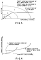
- FIG. 3 shows a relationship between a target locating coverage of the milli-wave radar system 11 and stereo-camera system 12 and an approach route of flying object 21.
- FIG. 4 shows a relationship between a target location error of the milli-wave radar system 11 and stereo-camera system 12 and a straight-line distance to the target.
- the vertical axis indicates the altitude of the target and the horizontal axis indicates a horizontal distance from, e.g. the landing point O to the target.
- symbol X indicates a flight path of the flying body 21 from point X1 to point X2, as shown in FIG. 1.
- the vertical axis indicates a target location error and the horizontal axis indicates a straight-line distance from, e.g. the landing point O to the target.
- Symbol M indicates a target location error of the milli-wave radar system 11 in relation to the straight-line distance
- symbol S a target location error of the stereo-camera system 12 in relation to the straight-line distance.
- the target locating coverage of the milli-wave radar system 11 reaches farther than that of the stereo-camera system 12.
- the locating coverage of the milli-wave radar system 11 is less influenced by rain, fog, etc. than that of the stereo-camera system 12.
- the target location error of the stereo-camera system 12 is less than that of the milli-wave radar system 11 in a close range (near landing point O). Accordingly, the flying object 21 can be guided to exactly land on the small-space landing point O. In addition, the stereo-camera system 12 is not greatly influenced by rain, fog, etc. in the close range.
- the milli-wave radar system 11 Since the milli-wave radar system 11 has a transmission blind period (i.e. a reception halt period in a transmission pulse emission period), the minimum detection distance cannot be reduced to a level of the stereo-camera system 12.
- the milli-wave radar system 11 which is less susceptible to rain, fog, etc.
- the stereo-camera system 12 which has a less target location error, is used in the close range just before the landing.
- the controller 13 delivers position information of the flying object 21 to the milli-wave radar system 11 over the line 14.
- the position information of the flying object 21 to be transmitted by the controller 13 is delivered to the controller 13 from the control apparatus 32, which acquires over the line 33 the self-position information of the flying object 21 acquired by a navigation system (not shown), etc.
- the position information is acquired by another long-distance sensor (not shown).
- the milli-wave radar system 11 captures the object 21 and starts to track it.
- the system 11 continuously locates the flying object 21 and transmits a locating result to the controller 13 over the line 14 as target position information.
- the target position information is then transmitted to the control apparatus 32 over the line 31.
- the control apparatus 32 Based on the input target position information, the control apparatus 32 issues a flight instruction to the flying object 21 over the line 33. At this time, the locating result of the milli-wave radar system 11 is transmitted to the stereo-camera 12, too, over the line 15 as target position information. The stereo-camera system 12, however, does not start tracking since the object 21 is out of the locating coverage.
- the stereo-camera system 12 starts detection.
- the target position information detected by the stereo-camera system 12 is transmitted to the controller 13 over the line 15.
- the controller 13 correlates the target position information transmitted from the stereo-camera system 12 with the information of the flying object 21 which has been tracked by the milli-wave radar system 11 thus far. If a high correlation result is obtained, the locating result to be adopted is switched to that of the stereo-camera system 12 and this locating result is delivered to the control apparatus 32 as target position information.
- the series of these operations are normally carried out while the flying object 21 is being present in the coverage B in which the locating coverage (B+C in FIG. 3) of the milli-wave radar system 11 overlaps the locating coverage (A+B in FIG. 3) of the stereo-camera system 12.
- the control apparatus 32 guides the flying object 21 to the landing point O. Even if the tracking by the stereo-camera system 12 is locked off due to, e.g. temporary shut-off of the visual field of the camera, if the flying object 21 is being in the coverage B, the milli-wave radar system 11 continues the tracking. Thus, the target position information obtained by the milli-wave radar system 11 may be used for supplementation. Accordingly, after the temporary shut-off of the visual field has ended, the stereo-camera system 12 can track the object 21 once again, following the above procedures.
- the flying object 21 is present in the coverage A, latest target position information cannot be obtained by the milli-wave radar system 11. However, the object 21 may be recaptured by continuing prediction of the target position on the basis of the target position information and movement information obtained at the time the tracking of the stereo-camera system 12 is locked off. In this case, since the flying object 21 is in the close range, the precision in prediction is very high. Needless to say, however, the minimum detection distance of the milli-wave radar system 11 should desirably be reduced as small as possible.
- the flying object 21 has a hovering function, as in the case of a helicopter, it is one way to make the flying object 21 remain at the same position in the air until the temporary shut-off of the visual field of the stereo-camera system 12 will end.
- the milli-wave radar system 11 and stereo-camera system 12 are mounted on the single gimbal 41.
- the milli-wave radar system 11 and stereo-camera system 12 have a constant positional relationship and the same visual line direction.
- a displacement in angular reference axes of both systems 11 and 12 is small, and the precision in target tracking switching is high.
- the milli-wave radar system 11 and stereo-camera system 12 may be mounted at different locations within the housing body 1.
- the milli-wave radar system 11 and stereo-camera system 12 have respective angular references and an error will occur between the angular references. Consequently, it becomes difficult to find a good correlation in target position information at the time of target tracking switching. It is desirable, therefore, to mount the milli-wave radar system 11 and stereo-camera system 12 on the same gimbal 41.
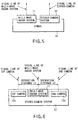
- FIG. 6 shows a second embodiment of the invention.
- the stereo-camera system 12 comprises at least a first camera 12a and a second camera 12b.
- the distance between the first and second cameras 12a and 12b and the target can be calculated by using the theory of triangulation, if a separation distance between the first and second cameras 12a and 12b and the target directions (angles) to the same target are found.
- the target angles are found by the function of the camera itself. Based on these data, the stereo-camera 12 can perform target location.
- the separation distance between the first and second cameras 12a and 12b in the stereo-camera system is sufficiently less than the target locating distance. It can be said from the theory of triangulation that the precision in measuring distance increases as the separation distance is larger. If the separation distance between the first and second cameras 12a and 12b is increased in order to enhance the precision in measuring distance, the size of the entire system including the milli-wave radar system increases.
- the first and second cameras 12a and 12b are arranged symmetrical with respect to the milli-wave radar system 11. Thereby, the space for installation is reduced while the precision in measuring distance is maintained. Thus, the target locating system can be reduced in size and the precision in measuring distance can be enhanced.
- an error in target locating results of the milli-wave radar system 11 and stereo-camera system 12 due to a displacement of visual lines of the milli-wave radar system 11 and stereo-camera system 12 is reduced.
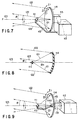
- a third embodiment of the present invention will now be described with reference to FIG. 7.
- a conical tracking system is adopted in the milli-wave radar system 11.
- the target locating system for the milli-wave radar system 11 is not specified.
- reference numeral 111 is a primary horn serving as a primary radiator.
- the primary horn 111 is connected over a feed line 113 to a transmission/reception system 112 including a transmitter and a receiver.
- the primary horn 111 emits and receives an antenna beam.
- Reference numeral 114 denotes a reflector, e.g. a parabolic reflector.
- the reflector 114 is situated opposed to a radiation surface of an antenna beam radiated by the primary horn 111, and reflects the antenna beam.
- the reflector 114 is selectively rotated in directions Z1 and Z2 by an antenna drive system 115 disposed in rear of the reflector 114.
- the primary horn 111 and reflector 114 are arranged so that the centers of their mutually opposed faces may substantially coincide.
- a transmission signal produced by the transmitter (not shown) in the transmission/reception system 112 is supplied to the primary horn 111 over the feed line 113.
- the primary horn 111 radiates the transmission signal to the reflector 114 as a beam 121.
- An antenna beam 122 reflected by the reflector 114 is radiated to the space.
- a reception signal received by the primary horn 111 is supplied, in a reverse direction to the transmission mode, to the receiver (not shown) in the transmission/reception system 112 over the feed line 113.
- the reflector 114 is inclined such that the antenna beam 122 is offset by an angle ⁇ with respect to the antenna visual line 123 (indicated by a two-dot-and-dash line in FIGS. 7 and 8). If the reflector 114 is rotated by the antenna drive system 115 about the antenna visual line 123, the antenna beam 122 describes a conical locus at an angle ⁇ with respect to the center axis or the antenna visual line 123. In other words, the antenna beam 122 is scanned conically.
- the feed line 113 from the transmission/reception system 112 to the primary horn 111 is extended from the outside of the reflector 114 to the reflection surface of the reflector 114 without passing through the antenna drive system 115. Since the transmission/reception system 112 is disposed near the antenna drive system 115 on the rear side of the reflector 114, the feed line 113 reaches the primary horn 111 from the transmission/reception system 112, passing by the periphery of the reflector 114.
- the conical scan of the antenna beam 122 is achieved by rotating the reflector 114, and the feed line 113 is made to extend from the transmission/reception system 112 to the primary horn 111, without passing through the antenna drive system 115.
- the primary horn 111, transmission/reception system 112 and feed line 113 are fixed as a beam generation source.
- the primary horn 111 and feed line 113 may not be provided with a rotary drive mechanism and a rotary joint etc.
- the factors of degrading the quality such as noise mixing, amplitude variation, or phase variation which are provided to antenna beam 122 by the rotary drive mechanism and rotary joint will be eliminated. Accordingly, stable transmission/reception of the beam can be achieved.
- the feed line 113 can be used in a fixed state between the transmission/reception system 112 and primary horn 111, for example, without rotating the feed line 113.
- the feed line 113 itself may not be damaged, and the reliability of the entire system can be enhanced.
- the antenna beam 122 reflected from the reflector 114 is less blocked by, e.g. an obstruction, and the antenna efficiency is less deteriorated.
- FIG. 9 shows a fourth embodiment of the present invention.
- the reflector 114 has a through-hole 131 at a central portion 114a corresponding to its rotational axis.
- the through-hole 131 extends from the reflector 114 to the antenna drive system 115.
- the feed line 113 extending from the transmission/reception system 112 to the primary horn 111 is passed through the through-hole 131.
- This structure is advantageous when the transmission/reception system 112 needs to be disposed behind the reflector 114 and antenna drive system 115 because of limitations to the disposition of the parts, or when the space for the feed line 113 cannot be provided around the reflector 114.
- the through-hole 131 is formed at the rotational axis of the reflector 114, and the feed line 113 extending from the transmission/reception system 112 to the primary horn 111 is passed through the through-hole 131.
- the feed line 113 may be passed through the through-hole 131 formed in the reflector 114 and antenna drive system 115, thus same advantage can be obtained.
- the milli-wave radar system 11 may be replaced with an electronic scan type antenna and the stereo-camera system 12 may be modified to have a wide field of view.
- the gimbal mechanism is dispensed with and the whole sensor can be fixed. Therefore, the precision in target locating can be enhanced.
- the target tracking system for the milli-wave radar system 11 may be freely chosen, and different advantages may be obtained by the chosen system.
- the wavelength band used in the stereo-camera system 12 may be freely chosen, depending on the environment of use.
- the flying object 21 being about to land is captured and tracked by the milli-wave radar system 11, which is less susceptible to weather, etc., in a range between a maximum detection distance of the milli-wave radar system 11 and the vicinity of the landing point O, and the flying object 21 is, in turn, captured and tracked by the stereo-camera system 12 with high locating precision at the landing point O.
- the locating distance for the flying object 21 being about to land is less decreased due to weather, etc., and exact target locating can be carried out in the vicinity of the landing point.
- the target position information of the flying object 21 obtained by the milli-wave radar system 11 and the target position information of the flying object 21 obtained by the stereo-camera system 12 is transmitted to the control apparatus 32 via the controller 13.
- the control apparatus 32 guides the flying object 21 to the vicinity of the landing point O, using the target position information from the milli-wave radar system 11 which is less susceptible to weather, etc.
- the control apparatus 32 guides the flying object 21 to the landing point O, using the target position information from the stereo-camera system 12 with high location precision.
- the flying object 21 can be exactly guided to the landing point, without influence of weather, etc.
- the milli-wave radar system 11 and stereo-camera system 12 are mounted on the same gimbal 41.
- the stereo-camera system 12 comprises the first camera 12a and second camera 12b
- the first and second cameras 12a and 12b are arranged symmetrical with respect to the milli-wave radar system 11.
- the target tracking system of the milli-wave radar system 11 may be variously modified, for example, by adopting the conical tracking system.
- the transmission/reception system can be simplified, and the whole system can be reduced in size, weight and cost. If the milli-wave radar system 11 is replaced with the electronic scan type antenna and the stereo-camera system 12 is modified to have a wide field of view, a desired locating coverage can be achieved without using the gimbal mechanism.
- the target detection probability or locating precision may be enhanced by providing the flying object 21 with a corner reflector for milli-wave radar or a marker for stereo-camera, which serves as a locating reference means.
Landscapes
- Engineering & Computer Science (AREA)
- Radar, Positioning & Navigation (AREA)
- Remote Sensing (AREA)
- Physics & Mathematics (AREA)
- General Physics & Mathematics (AREA)
- Computer Networks & Wireless Communication (AREA)
- Electromagnetism (AREA)
- Aviation & Aerospace Engineering (AREA)
- Automation & Control Theory (AREA)
- Radar Systems Or Details Thereof (AREA)
Applications Claiming Priority (6)
| Application Number | Priority Date | Filing Date | Title |
|---|---|---|---|
| JP23487897 | 1997-08-29 | ||
| JP23487897A JP3305989B2 (ja) | 1997-08-29 | 1997-08-29 | 目標標定装置及び着陸誘導装置 |
| JP234878/97 | 1997-08-29 | ||
| JP242832/97 | 1997-09-08 | ||
| JP24283297A JPH1188029A (ja) | 1997-09-08 | 1997-09-08 | 円錐走査型アンテナ装置 |
| JP24283297 | 1997-09-08 |
Publications (2)
| Publication Number | Publication Date |
|---|---|
| EP0899580A2 true EP0899580A2 (de) | 1999-03-03 |
| EP0899580A3 EP0899580A3 (de) | 2000-02-02 |
Family
ID=26531816
Family Applications (1)
| Application Number | Title | Priority Date | Filing Date |
|---|---|---|---|
| EP98116008A Withdrawn EP0899580A3 (de) | 1997-08-29 | 1998-08-25 | System zur Ortung eines Zieles und Anflug-Leitsystem |
Country Status (2)
| Country | Link |
|---|---|
| US (1) | US6181271B1 (de) |
| EP (1) | EP0899580A3 (de) |
Cited By (7)
| Publication number | Priority date | Publication date | Assignee | Title |
|---|---|---|---|---|
| US6181271B1 (en) * | 1997-08-29 | 2001-01-30 | Kabushiki Kaisha Toshiba | Target locating system and approach guidance system |
| GB2355876A (en) * | 1999-10-25 | 2001-05-02 | Roke Manor Research | Location and tracking system. |
| EP1441318A3 (de) * | 2003-01-21 | 2004-12-08 | Hitachi, Ltd. | Sicherheitssystem |
| EP1709568A4 (de) * | 2003-12-15 | 2009-07-29 | Sarnoff Corp | Verfahren und vorrichtung zur objektverfolgung vor einer anstehende-kollision-detektion |
| CN101995572A (zh) * | 2009-08-13 | 2011-03-30 | Tk控股公司 | 对象感测系统 |
| CN113223090A (zh) * | 2021-04-16 | 2021-08-06 | 天津开发区文博电子有限公司 | 铁路调车动态视觉监控方法 |
| CN121069334A (zh) * | 2025-08-26 | 2025-12-05 | 北京环境特性研究所 | 一种外场机载双站雷达测量标定的方法 |
Families Citing this family (23)
| Publication number | Priority date | Publication date | Assignee | Title |
|---|---|---|---|---|
| JP2001344597A (ja) * | 2000-05-30 | 2001-12-14 | Fuji Heavy Ind Ltd | 融合視界装置 |
| CA2478255C (en) * | 2002-03-07 | 2010-01-05 | Lance G. Taylor | Intelligent selectively-targeted communications systems and methods |
| JP4253239B2 (ja) * | 2003-10-07 | 2009-04-08 | 富士重工業株式会社 | 画像認識を用いた航法装置 |
| US7889113B2 (en) * | 2003-10-10 | 2011-02-15 | L-3 Communications Security and Detection Systems Inc. | Mmw contraband screening system |
| US7301497B2 (en) * | 2005-04-05 | 2007-11-27 | Eastman Kodak Company | Stereo display for position sensing systems |
| WO2006123615A1 (ja) | 2005-05-19 | 2006-11-23 | Olympus Corporation | 距離計測装置、距離計測方法および距離計測プログラム |
| US7395156B2 (en) * | 2005-06-23 | 2008-07-01 | Raytheon Company | System and method for geo-registration with global positioning and inertial navigation |
| US7321330B2 (en) * | 2005-10-03 | 2008-01-22 | Sri Sports Limited | Ball measuring apparatus |
| ES2371758T3 (es) * | 2005-11-09 | 2012-01-09 | Saab Ab | Sistema de sensores múltiples. |
| US7693617B2 (en) * | 2006-09-19 | 2010-04-06 | The Boeing Company | Aircraft precision approach control |
| US7365696B1 (en) * | 2006-10-04 | 2008-04-29 | Weather Detection Systems, Inc. | Multitransmitter RF rotary joint free weather radar system |
| WO2009012231A1 (en) * | 2007-07-17 | 2009-01-22 | Laufer Wind Group Llc | Method and system for reducing light pollution |
| US8026841B2 (en) * | 2008-09-18 | 2011-09-27 | Bae Systems Controls Inc. | Range and azimuth resolution enhancement for real-beam radar |
| US8125529B2 (en) * | 2009-02-09 | 2012-02-28 | Trimble Navigation Limited | Camera aiming using an electronic positioning system for the target |
| DE102009009896B4 (de) * | 2009-02-20 | 2011-02-10 | Eads Deutschland Gmbh | Verfahren und Vorrichtung zur Erfassung von Zielobjekten |
| US9057609B2 (en) * | 2009-03-27 | 2015-06-16 | National University Of Defense Technology | Ground-based camera surveying and guiding method for aircraft landing and unmanned aerial vehicle recovery |
| GB2488699B (en) | 2009-11-03 | 2014-09-17 | Vawd Applied Science & Technology Corp | Standoff range sense through obstruction radar system |
| US20110221934A1 (en) * | 2010-03-12 | 2011-09-15 | Ideal Innovations Incorporated | Ground-Based Instrumentation Operating with Airborne Wave Reflectors |
| EP2453386B1 (de) * | 2010-11-11 | 2019-03-06 | LG Electronics Inc. | Multimedia-Vorrichtung, Mehrfachbildsensoren mit verschiedenen Typen und Steuerverfahren dafür |
| US10241186B2 (en) * | 2014-02-24 | 2019-03-26 | H4 Engineering, Inc. | Cooperative automatic tracking |
| CN106933249B (zh) * | 2017-04-28 | 2023-04-07 | 安徽民航机场集团有限公司 | 一种航空器实时跟踪引导系统 |
| JP7274856B2 (ja) | 2018-12-11 | 2023-05-17 | スリーエム イノベイティブ プロパティズ カンパニー | 位置検出システム、位置検出方法、角度検出方法、マーカー |
| CN110233352A (zh) * | 2019-06-02 | 2019-09-13 | 中国电子科技集团公司第三十九研究所 | 基于波束倾斜补偿与圆锥扫描融合的深空目标高精度跟踪方法 |
Family Cites Families (18)
| Publication number | Priority date | Publication date | Assignee | Title |
|---|---|---|---|---|
| US5268680A (en) * | 1970-09-08 | 1993-12-07 | Raytheon Company | Combined infrared-radar detection system |
| US3900846A (en) * | 1974-01-14 | 1975-08-19 | Lockheed Electronics Co | Computer automated radar terminal system |
| US3934250A (en) * | 1974-06-07 | 1976-01-20 | The United States Of America As Represented By The Secretary Of The Navy | Helicopter blind landing and hover system |
| US4805015A (en) * | 1986-09-04 | 1989-02-14 | Copeland J William | Airborne stereoscopic imaging system |
| DE3830496C1 (de) * | 1988-09-08 | 1996-09-19 | Daimler Benz Aerospace Ag | Vorrichtung zum Erkennen und Verfolgen von Objekten |
| IL88263A (en) * | 1988-11-02 | 1993-03-15 | Electro Optics Ind Ltd | Navigation system |
| GB8925196D0 (en) * | 1989-11-08 | 1990-05-30 | Smiths Industries Plc | Navigation systems |
| JPH0470201A (ja) | 1990-07-11 | 1992-03-05 | Nippon Denshi Kiki Co Ltd | 走査アンテナ |
| JPH0561963A (ja) | 1991-09-04 | 1993-03-12 | Mitsubishi Electric Corp | 地球観測方法 |
| JPH0772920B2 (ja) | 1992-07-15 | 1995-08-02 | 東芝テスコ株式会社 | 航空機ドッキングガイダンス装置 |
| US5481479A (en) * | 1992-12-10 | 1996-01-02 | Loral Fairchild Corp. | Nonlinear scanning to optimize sector scan electro-optic reconnaissance system performance |
| US5983161A (en) * | 1993-08-11 | 1999-11-09 | Lemelson; Jerome H. | GPS vehicle collision avoidance warning and control system and method |
| JPH0821876A (ja) | 1994-07-06 | 1996-01-23 | Japan Radio Co Ltd | 複合レーダ装置 |
| JPH08146130A (ja) * | 1994-11-24 | 1996-06-07 | Mitsubishi Electric Corp | 空港面地上走行管制システム |
| US6056237A (en) * | 1997-06-25 | 2000-05-02 | Woodland; Richard L. K. | Sonotube compatible unmanned aerial vehicle and system |
| US5867256A (en) * | 1997-07-16 | 1999-02-02 | Raytheon Ti Systems, Inc. | Passive range estimation using image size measurements |
| EP0899580A3 (de) * | 1997-08-29 | 2000-02-02 | Kabushiki Kaisha Toshiba | System zur Ortung eines Zieles und Anflug-Leitsystem |
| JP3305989B2 (ja) * | 1997-08-29 | 2002-07-24 | 株式会社東芝 | 目標標定装置及び着陸誘導装置 |
-
1998
- 1998-08-25 EP EP98116008A patent/EP0899580A3/de not_active Withdrawn
- 1998-08-27 US US09/141,408 patent/US6181271B1/en not_active Expired - Fee Related
Cited By (10)
| Publication number | Priority date | Publication date | Assignee | Title |
|---|---|---|---|---|
| US6181271B1 (en) * | 1997-08-29 | 2001-01-30 | Kabushiki Kaisha Toshiba | Target locating system and approach guidance system |
| GB2355876A (en) * | 1999-10-25 | 2001-05-02 | Roke Manor Research | Location and tracking system. |
| EP1441318A3 (de) * | 2003-01-21 | 2004-12-08 | Hitachi, Ltd. | Sicherheitssystem |
| US7425983B2 (en) | 2003-01-21 | 2008-09-16 | Hitachi, Ltd. | Security system |
| EP1709568A4 (de) * | 2003-12-15 | 2009-07-29 | Sarnoff Corp | Verfahren und vorrichtung zur objektverfolgung vor einer anstehende-kollision-detektion |
| US7660438B2 (en) | 2003-12-15 | 2010-02-09 | Sarnoff Corporation | Method and apparatus for object tracking prior to imminent collision detection |
| CN101995572A (zh) * | 2009-08-13 | 2011-03-30 | Tk控股公司 | 对象感测系统 |
| EP2284568A3 (de) * | 2009-08-13 | 2012-02-22 | TK Holdings Inc. | Objektabtastsystem |
| CN113223090A (zh) * | 2021-04-16 | 2021-08-06 | 天津开发区文博电子有限公司 | 铁路调车动态视觉监控方法 |
| CN121069334A (zh) * | 2025-08-26 | 2025-12-05 | 北京环境特性研究所 | 一种外场机载双站雷达测量标定的方法 |
Also Published As
| Publication number | Publication date |
|---|---|
| US6181271B1 (en) | 2001-01-30 |
| EP0899580A3 (de) | 2000-02-02 |
Similar Documents
| Publication | Publication Date | Title |
|---|---|---|
| US6181271B1 (en) | Target locating system and approach guidance system | |
| EP2065724B1 (de) | Lichterkennungs- und -entfernungsmessungssystem | |
| US10935991B2 (en) | System and method to reflect radar using aircraft | |
| JP6654736B2 (ja) | 結像およびレーザ通信を複合したシステム | |
| US7728756B2 (en) | Wide area high resolution SAR from a moving and hovering helicopter | |
| US6795031B1 (en) | Mechanically scanned parabolic reflector antenna | |
| US5673057A (en) | Three axis beam waveguide antenna | |
| JP3305989B2 (ja) | 目標標定装置及び着陸誘導装置 | |
| CN113655461A (zh) | 一种具有棱镜反射结构的激光雷达装置 | |
| JP2005244362A (ja) | ミリ波通信システム、ミリ波送信装置およびミリ波受信装置 | |
| KR102293816B1 (ko) | 복합구동형 레이저시스템 및 제어방법 | |
| US12386042B2 (en) | Light signal deflecting device for an optical measuring system for detecting objects, measuring system, and method for operating a light signal deflecting device | |
| KR100331785B1 (ko) | 선박과같은이동체를위한위성통신용자동추적안테나 | |
| CN111200461B (zh) | 用于激光雷达的光通信系统及其制造方法 | |
| CN113820721B (zh) | 一种收发分离的激光雷达系统 | |
| CN213122289U (zh) | 一种激光测距设备及具有其的激光雷达 | |
| JPH06268563A (ja) | 移動体における無線中継方式 | |
| JP7535483B2 (ja) | レーダーシステム | |
| JPH0464082A (ja) | 自動追尾装置用の反射体 | |
| JP2853685B2 (ja) | 飛行経路測定装置 | |
| JPH10132933A (ja) | 人工衛星搭載用のレーザレーダシステムおよびレーザレーダ | |
| JP4651068B2 (ja) | 2周波cwレーダ | |
| JPH0476482A (ja) | 合成開口レーダ装置 | |
| JP3840520B2 (ja) | 電波反射体を用いた移動体の航法方法 | |
| JP2003207563A (ja) | レーダ装置 |
Legal Events
| Date | Code | Title | Description |
|---|---|---|---|
| PUAI | Public reference made under article 153(3) epc to a published international application that has entered the european phase |
Free format text: ORIGINAL CODE: 0009012 |
|
| 17P | Request for examination filed |
Effective date: 19980922 |
|
| AK | Designated contracting states |
Kind code of ref document: A2 Designated state(s): DE FR GB |
|
| AX | Request for extension of the european patent |
Free format text: AL;LT;LV;MK;RO;SI |
|
| RIC1 | Information provided on ipc code assigned before grant |
Free format text: 6G 01S 13/86 A, 6G 01S 13/91 B, 6G 01S 13/72 B, 6G 01S 3/786 B, 6G 01C 3/08 B, 6H 01Q 3/20 B, 6G 01S 11/12 B |
|
| PUAL | Search report despatched |
Free format text: ORIGINAL CODE: 0009013 |
|
| AK | Designated contracting states |
Kind code of ref document: A3 Designated state(s): AT BE CH CY DE DK ES FI FR GB GR IE IT LI LU MC NL PT SE |
|
| AX | Request for extension of the european patent |
Free format text: AL;LT;LV;MK;RO;SI |
|
| AKX | Designation fees paid |
Free format text: DE FR GB |
|
| STAA | Information on the status of an ep patent application or granted ep patent |
Free format text: STATUS: THE APPLICATION HAS BEEN WITHDRAWN |
|
| 18W | Application withdrawn |
Effective date: 20070216 |