EP0901036A1 - Optisches Beobachtungssystem und optisches Gerät unter Verwendung desselben - Google Patents
Optisches Beobachtungssystem und optisches Gerät unter Verwendung desselben Download PDFInfo
- Publication number
- EP0901036A1 EP0901036A1 EP98116673A EP98116673A EP0901036A1 EP 0901036 A1 EP0901036 A1 EP 0901036A1 EP 98116673 A EP98116673 A EP 98116673A EP 98116673 A EP98116673 A EP 98116673A EP 0901036 A1 EP0901036 A1 EP 0901036A1
- Authority
- EP
- European Patent Office
- Prior art keywords
- eyeball
- optical system
- coating
- antifogging
- antifogging coating
- Prior art date
- Legal status (The legal status is an assumption and is not a legal conclusion. Google has not performed a legal analysis and makes no representation as to the accuracy of the status listed.)
- Granted
Links
- 230000003287 optical effect Effects 0.000 title claims abstract description 104
- 238000000576 coating method Methods 0.000 claims abstract description 79
- 239000011248 coating agent Substances 0.000 claims abstract description 76
- 210000005252 bulbus oculi Anatomy 0.000 claims abstract description 36
- 210000001508 eye Anatomy 0.000 claims abstract description 21
- XLYOFNOQVPJJNP-UHFFFAOYSA-N water Substances O XLYOFNOQVPJJNP-UHFFFAOYSA-N 0.000 claims abstract description 21
- 150000004703 alkoxides Chemical class 0.000 claims description 17
- 229910052751 metal Inorganic materials 0.000 claims description 8
- 239000002184 metal Substances 0.000 claims description 8
- 239000000203 mixture Substances 0.000 claims description 7
- 239000010409 thin film Substances 0.000 claims description 6
- 239000002131 composite material Substances 0.000 claims description 4
- 230000007062 hydrolysis Effects 0.000 claims description 4
- 238000006460 hydrolysis reaction Methods 0.000 claims description 4
- 229910010272 inorganic material Inorganic materials 0.000 claims description 4
- 239000011147 inorganic material Substances 0.000 claims description 4
- 238000006068 polycondensation reaction Methods 0.000 claims description 4
- 229920000642 polymer Polymers 0.000 claims description 4
- 238000001514 detection method Methods 0.000 abstract description 5
- 230000000694 effects Effects 0.000 description 19
- 238000000034 method Methods 0.000 description 16
- 230000000007 visual effect Effects 0.000 description 16
- 239000003795 chemical substances by application Substances 0.000 description 11
- 238000010276 construction Methods 0.000 description 10
- 230000011514 reflex Effects 0.000 description 9
- 230000008878 coupling Effects 0.000 description 7
- 238000010168 coupling process Methods 0.000 description 7
- 238000005859 coupling reaction Methods 0.000 description 7
- OKKJLVBELUTLKV-UHFFFAOYSA-N Methanol Chemical compound OC OKKJLVBELUTLKV-UHFFFAOYSA-N 0.000 description 6
- 239000011521 glass Substances 0.000 description 6
- 241001274961 Rubus repens Species 0.000 description 5
- 210000000078 claw Anatomy 0.000 description 5
- RTAQQCXQSZGOHL-UHFFFAOYSA-N Titanium Chemical compound [Ti] RTAQQCXQSZGOHL-UHFFFAOYSA-N 0.000 description 4
- 239000012298 atmosphere Substances 0.000 description 4
- 239000000758 substrate Substances 0.000 description 4
- 229920002125 Sokalan® Polymers 0.000 description 3
- 210000004087 cornea Anatomy 0.000 description 3
- 239000000463 material Substances 0.000 description 3
- 210000001747 pupil Anatomy 0.000 description 3
- 239000004094 surface-active agent Substances 0.000 description 3
- 229920003171 Poly (ethylene oxide) Polymers 0.000 description 2
- 229910052782 aluminium Inorganic materials 0.000 description 2
- 230000005540 biological transmission Effects 0.000 description 2
- 239000003054 catalyst Substances 0.000 description 2
- 238000009833 condensation Methods 0.000 description 2
- 230000005494 condensation Effects 0.000 description 2
- 238000013461 design Methods 0.000 description 2
- XXBDWLFCJWSEKW-UHFFFAOYSA-N dimethylbenzylamine Chemical compound CN(C)CC1=CC=CC=C1 XXBDWLFCJWSEKW-UHFFFAOYSA-N 0.000 description 2
- 238000007598 dipping method Methods 0.000 description 2
- 230000007613 environmental effect Effects 0.000 description 2
- 239000004615 ingredient Substances 0.000 description 2
- 238000004519 manufacturing process Methods 0.000 description 2
- 229920000233 poly(alkylene oxides) Polymers 0.000 description 2
- 239000004584 polyacrylic acid Substances 0.000 description 2
- 230000029058 respiratory gaseous exchange Effects 0.000 description 2
- 229920002845 Poly(methacrylic acid) Polymers 0.000 description 1
- 238000010521 absorption reaction Methods 0.000 description 1
- XAGFODPZIPBFFR-UHFFFAOYSA-N aluminium Chemical compound [Al] XAGFODPZIPBFFR-UHFFFAOYSA-N 0.000 description 1
- PNEYBMLMFCGWSK-UHFFFAOYSA-N aluminium oxide Inorganic materials [O-2].[O-2].[O-2].[Al+3].[Al+3] PNEYBMLMFCGWSK-UHFFFAOYSA-N 0.000 description 1
- 238000000137 annealing Methods 0.000 description 1
- 229910052790 beryllium Inorganic materials 0.000 description 1
- 230000015572 biosynthetic process Effects 0.000 description 1
- 229910052796 boron Inorganic materials 0.000 description 1
- 229910052791 calcium Inorganic materials 0.000 description 1
- 150000001875 compounds Chemical class 0.000 description 1
- 229910052593 corundum Inorganic materials 0.000 description 1
- 230000006866 deterioration Effects 0.000 description 1
- 238000002474 experimental method Methods 0.000 description 1
- 239000010408 film Substances 0.000 description 1
- 125000000524 functional group Chemical group 0.000 description 1
- 229910052736 halogen Inorganic materials 0.000 description 1
- 150000002367 halogens Chemical class 0.000 description 1
- 238000010438 heat treatment Methods 0.000 description 1
- 238000005286 illumination Methods 0.000 description 1
- 229910052742 iron Inorganic materials 0.000 description 1
- GJRQTCIYDGXPES-UHFFFAOYSA-N iso-butyl acetate Natural products CC(C)COC(C)=O GJRQTCIYDGXPES-UHFFFAOYSA-N 0.000 description 1
- FGKJLKRYENPLQH-UHFFFAOYSA-M isocaproate Chemical compound CC(C)CCC([O-])=O FGKJLKRYENPLQH-UHFFFAOYSA-M 0.000 description 1
- OQAGVSWESNCJJT-UHFFFAOYSA-N isovaleric acid methyl ester Natural products COC(=O)CC(C)C OQAGVSWESNCJJT-UHFFFAOYSA-N 0.000 description 1
- 229910052744 lithium Inorganic materials 0.000 description 1
- 238000012423 maintenance Methods 0.000 description 1
- 239000003960 organic solvent Substances 0.000 description 1
- 230000002940 repellent Effects 0.000 description 1
- 239000005871 repellent Substances 0.000 description 1
- 239000012858 resilient material Substances 0.000 description 1
- 239000011347 resin Substances 0.000 description 1
- 229920005989 resin Polymers 0.000 description 1
- 150000003839 salts Chemical class 0.000 description 1
- 229910052710 silicon Inorganic materials 0.000 description 1
- 239000002904 solvent Substances 0.000 description 1
- 230000003595 spectral effect Effects 0.000 description 1
- 239000007921 spray Substances 0.000 description 1
- 238000012360 testing method Methods 0.000 description 1
- 229910052718 tin Inorganic materials 0.000 description 1
- 229910052719 titanium Inorganic materials 0.000 description 1
- BPSIOYPQMFLKFR-UHFFFAOYSA-N trimethoxy-[3-(oxiran-2-ylmethoxy)propyl]silane Chemical compound CO[Si](OC)(OC)CCCOCC1CO1 BPSIOYPQMFLKFR-UHFFFAOYSA-N 0.000 description 1
- 229910052720 vanadium Inorganic materials 0.000 description 1
- 229910001845 yogo sapphire Inorganic materials 0.000 description 1
- 229910052726 zirconium Inorganic materials 0.000 description 1
Images


Classifications
-
- G—PHYSICS
- G03—PHOTOGRAPHY; CINEMATOGRAPHY; ANALOGOUS TECHNIQUES USING WAVES OTHER THAN OPTICAL WAVES; ELECTROGRAPHY; HOLOGRAPHY
- G03B—APPARATUS OR ARRANGEMENTS FOR TAKING PHOTOGRAPHS OR FOR PROJECTING OR VIEWING THEM; APPARATUS OR ARRANGEMENTS EMPLOYING ANALOGOUS TECHNIQUES USING WAVES OTHER THAN OPTICAL WAVES; ACCESSORIES THEREFOR
- G03B13/00—Viewfinders; Focusing aids for cameras; Means for focusing for cameras; Autofocus systems for cameras
- G03B13/02—Viewfinders
-
- G—PHYSICS
- G02—OPTICS
- G02B—OPTICAL ELEMENTS, SYSTEMS OR APPARATUS
- G02B1/00—Optical elements characterised by the material of which they are made; Optical coatings for optical elements
- G02B1/10—Optical coatings produced by application to, or surface treatment of, optical elements
-
- G—PHYSICS
- G02—OPTICS
- G02B—OPTICAL ELEMENTS, SYSTEMS OR APPARATUS
- G02B1/00—Optical elements characterised by the material of which they are made; Optical coatings for optical elements
- G02B1/10—Optical coatings produced by application to, or surface treatment of, optical elements
- G02B1/18—Coatings for keeping optical surfaces clean, e.g. hydrophobic or photo-catalytic films
-
- G—PHYSICS
- G03—PHOTOGRAPHY; CINEMATOGRAPHY; ANALOGOUS TECHNIQUES USING WAVES OTHER THAN OPTICAL WAVES; ELECTROGRAPHY; HOLOGRAPHY
- G03B—APPARATUS OR ARRANGEMENTS FOR TAKING PHOTOGRAPHS OR FOR PROJECTING OR VIEWING THEM; APPARATUS OR ARRANGEMENTS EMPLOYING ANALOGOUS TECHNIQUES USING WAVES OTHER THAN OPTICAL WAVES; ACCESSORIES THEREFOR
- G03B2213/00—Viewfinders; Focusing aids for cameras; Means for focusing for cameras; Autofocus systems for cameras
- G03B2213/02—Viewfinders
- G03B2213/025—Sightline detection
Definitions
- the present invention relates to observation optical systems, optical attachments and eyeball-characteristic detecting systems and, more particularly, to such systems which are suited to be used in the viewfinder optical systems of cameras or the like.
- Fig. 1 is a longitudinal section view of the conventional single-lens reflex camera.
- a camera body 101 with a photographic lens 102 contains a return mirror 103, a viewfinder system 104 composed of a focusing screen 105, a pentagonal prism 106 and an eyepiece lens 107, and a back cover 108.
- the photographer while keeping hold of his or her eye 109 in axial alignment with the eyepiece lens 107, observes an image formed on the focusing screen 105 by the photographic lens 102.
- the method using the surface active agent does not insure that, as the outer surface of the eyepiece lens is somewhat deep from the frame thereof, the solution is uniformly applied to the entire area of that surface.
- the antifogging effect is ensured only temporarily.
- the surface active agent when applied to the surface makes it hydrophile. In other words, the wettability is enhanced, thus producing the antifogging effect. Therefore, a thin film of water is formed on the surface. As the condensed amount of moisture increases, the image to be observed is possible to eventually distort.
- the length L of the hood 110 must be made longer than a certain value to obtain a sufficient antifogging effect. It varies depending on the conditions of the environment. For example, at a temperature of -10°C, the desired length L is found to be 20 mm or longer. Otherwise, no antifogging effect can be obtained.
- the eye 109 of the observer is necessarily spaced away from the eyepiece lens 107 by a distance of about 25 mm.
- a numerical variable called "eye relief" is usually adopted. For a viewfinder system whose eye relief exceeds 25 mm, its physical size becomes large. Therefore, a problem arises in that its price becomes high.
- the observation optical system such as the viewfinder of the camera with a visual line detecting device for detecting that location on the viewfinder image which the observer looks at, or for detecting the direction of a visual line of the observer.
- fogging due to the temperature or humidity affects some optical parts of the above-described optical systems for illumination and for receiving the reflected light. If the fogging occurs, then not only the visual line and diopter become impossible to detect but also a faulty operation will take place to effect an unintentional result.
- the present invention has been made with the above described problem in mind, and it is a general object of the invention is to realize an observation optical system, an optical attachment, or an eyeball-characteristic detecting system of high precision accuracy which has a permanent antifogging effect, while still not sacrificing the comfortableness for viewing.
- an observation optical system whose eye relief is below 25 mm, in which an antifogging coating having a property of absorbing water is formed on at least one surface in members constituting the eyepiece optical system.
- an optical apparatus comprising the observation optical system of the invention.
- an optical attachment which is releasably mounted between an eyepiece optical system and the eye of the observer, which comprises an optical member and means for shielding a space between the optical member and the eyepiece optical system substantially from outside air, wherein an antifogging coating having a property of absorbing water is formed on the optical member.
- an eyeball-characteristic detecting system which comprises a light source for emitting light for illuminating an eyeball of an observer, a light receiving element arranged to receive light reflected from the eyeball through an eyepiece optical system, an optical member provided in an optical path from the light source to the light receiving element, the optical member having at least one surface on which an antifogging coating is formed, and means for detecting a characteristic of the eyeball by utilizing a signal outputted from the light receiving element.
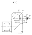
- Fig. 3 is a longitudinal section view of the construction of a single-lens reflex camera having an observation optical system according to an embodiment of the invention.
- a camera body 1 with a photographic lens 2 contains a return mirror 3, a viewfinder system 4 composed of a focusing screen 5, a pentagonal prism 6 and an eyepiece lens 7, and a back cover 8.
- the photographer while keeping hold of his or her eye 9 in axial alignment with the eyepiece lens 7, observes an image formed on the focusing screen 5 by the photographic lens 2.
- the observer While holding the camera in such a position, the observer looks through the viewfinder system. Then, the breath from the mouth or nose of the photographer ascends along the surface of the back cover 8, passing through the space between the eyepiece lens 7 and the eye 9.
- the ambient temperature is low, it is in the conventional arrangement that part of the breath touches the cold surface of the eyepiece lens 7, where the condensation of moisture results in fogging.
- the optical members constituting the eyepiece lens 7 at least one surface which is exposed to the open air, i.e., the surface 10 that is closest to the observer, is provided with an antifogging coating having a property of absorbing water. The eyepiece lens 7 is thus prevented from being fogged by the breath of the observer.
- the hood may be attached to the eyepiece lens 7, reducing the proportion of that part of the breath which directly hits the eyepiece lens 7. Fogging is thus made possible to avoid.
- the eye relief is shorter than 25 mm., such a method can hardly prevent the fogging from occurring completely.
- the observation optical system of the invention produces the greatest effect when the eye relief is shorter than 25 mm.
- the invention is more advantageous.
- antifoggy agents To form the antifogging coating having a property of absorbing water, many antifoggy agents are known.
- This antifoggy agent is a composition of (1) inorganic alkoxide and at least one polymer formed from this alkoxide by hydrolysis and poly-condensation and having OH radicals, (2) polyalkylene oxide, (3) catalyst, and (4) water-contained organic solvent.
- M(OR) n (X) a-n where M is an inorganic atom selected from the group consisting of Si, Al, Ti, Zr, Ca, Fe, V, Sn, Li, Be, B and P, R is alkyl radicals, X is alkyl radicals with or without functional groups, or halogen, "a” is the valence of M, and "n” is an integer of from 1 to "a”.
- polyethylene oxide is preferably used as the polyalkylene oxide cited above.
- N,N-dimethylbenzylamine is preferably used as the basic catalyst cited above.
- polyacrylic acids may be included. More specifically, polyacrylic acid, poly-methacrylic acid and their salts may be mentioned. At least one selected out of these is preferably used.
- the polyacrylic acid, N,N-dimethylbenzylamine and ⁇ -glycidoxy propyltrimethoxysilane are added to the methanol solution of 10% polyethylene oxide (mean molecular weight: 300,000).
- the mixture is stirred for 10 minutes.
- aluminum isoproxide was previously hydrolyzed, its methanol solution (containing 5% Al 2 O 3 ) is added.
- the mixture is stirred for 30 minutes.
- the thus-obtained solution is applied either to both surfaces of the eyepiece lens, or to the one of the surfaces which is exposed to the outside.
- the coating is dried (annealed) by heating to, and keeping at, 150°C for 10 minutes.
- the obtained eyepiece lens was incorporated in the camera and left lying for 2 hours in an atmosphere of -10°C. After that, in the same atmosphere, the observer looked through the viewfinder, while breathing through the mouth or nose. However, the eyepiece lens did not get fogged in every test.
- the coating on the lens surface must have a certain thickness.
- the coating is desired to be thickened to not less than at least 0.5 ⁇ m. A more desirable coating is 1 ⁇ m or thicker.
- the antifogging coating on the lens surface is desired to be 10 ⁇ m or less. If thinner than 5 ⁇ m, it is more desirable.
- the application of the antifoggy agent is carried out by any technique known in the art using the dipping method, the spray method or the spin method.
- the cycle of coating and annealing operations may be repeated twice or more.
- the first embodiment has been described in connection with the antifogging coating applied directly to an optical member having a refractive power, that is, the eyepiece lens
- a variation may be made by using a transparent plate of glass as the protection member having no refractive power at a closest position of the eyepiece optical system to the observer.
- the coating is applied to the one of the parallel flat surfaces of the plate which faces the observer, or both of them.
- the flat plane makes more uniform the coating than the surface of curvature and the plane accuracy is easier to hold than the surface accuracy.
- a plate of large size can be used as the substrate for applying the coating thereon. In the later process, it can be cut to a necessary size. So, it is advantageous even in the point of view of the mass production.
- Fig. 4 is a longitudinal section view of a single-lens reflex camera according to a second embodiment of the invention, where the same parts as those of Fig. 3 are denoted by the same reference numerals.
- an eyepiece lens 7' is different from the eyepiece lens 7 of the first embodiment in that its surfaces are not coated with the antifoggy agent.
- the second embodiment employs an antifogging unit 12 (optical attachment) including a transparent member 11 on the observer side of the eyepiece lens 7'.
- the transparent member 11 is a flat plate of glass whose both surfaces are parallel to each other, and at least the one of them which confronts the eye of the observer, namely, the surface 13, is coated with an antifoggy agent similar to that of the first embodiment.
- the antifogging unit 12 of the second embodiment is made attachable to and detachable from the camera body 1 by a mechanism described below.
- Figs. 5A and 5B in an enlarged scale show only the eyepiece lens of Fig. 4 and its neighborhood, with Fig. 5A in an axial sectional view and Fig. 5B in an elevation back view as looked from the observer.
- the antifogging unit 12 has an axial opening 14 of rectangular shape in which the transparent member 11 is fixedly mounted, and is movably fitted on a coupling frame 15 on the camera body 1.
- a claw member 16 fixedly secures the antifogging unit 12 to the coupling frame 15 of the camera.
- the left and right sides of the coupling frame 15 have grooves 17 formed therein.
- the claw member 16 which is made of a resilient material, has a letter "U" shape with the open side down, so that the space between its free ends 18 is horizontally expandable.
- the user puts the free ends 18 of the claw member 16 above the coupling frame 15 in alignment with the grooves 17 and slides the antifogging unit 12 downward until the free ends 18 of the claw member 16 drop over the corners of the coupling frame 15. The antifogging unit 12 is thus locked.
- the user presses the antifogging unit 12 from both sides at the upper half 19 thereof, thereby opening the free ends 18 of the claw member 16. While keeping the pressure, the user slides the antifogging unit 12 upward. The antifogging unit 12 is thus detached from the camera body 1.
- the space between the eyepiece lens 7' and the transparent member 11 is desired to be air-tightly shielded, especially at the bottom, so that the breath of the observer cannot enter that space.
- a gap of necessary minimum may be provided in between the coupling members. Even if so, almost no decrease of the antifogging effect has been found because the flow of breath is sufficiently blocked from entering.
- the second embodiment has been described as using the transparent member 11 of the antifogging unit 12 in the form of a parallel flat plate of glass, it is also possible that the transparent member 11 takes the form of a lens. With the antifogging coating on both surfaces or one surface of that lens, the antifogging unit 12 then gets not only the antifogging function but also a function of correcting the diopter.
- the antifogging coating may be constructed to have the antireflection effect.
- many schemes are already available. Of these, the one that allows the antifogging aspect and the antireflection aspect to be compatible and is excellent in durability is suitably used, as disclosed in Japanese Patent Application No. Hei 9-213269. This scheme is that a thin film of high refractive index is made from metal alkoxide or at least one of the composites of metal alkoxide and inorganic materials and that this film is sandwiched between the antifogging coatings described before.
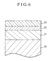
- Fig. 6 is a sectional view of the construction of a multi-layer antifogging coating which is given the antireflection effect by the scheme described above.
- a substrate glass 20 on which to apply such an antifogging coating corresponds to the eyepiece lens 7 of Fig. 3 or the transparent plate 11 of Fig. 4.
- the coating comprises a first antifog layer 21, an intermediate layer 22 of titan tetraisopropoxide and a second antifog layer 23 made of a similar material to that of the first antifog layer 21.
- the substrate glass 20 is depicted as a flat surface, but may have a curved surface, of course.
- the first antifog layer 21 is formed by using the same antifoggy agent as that of the first embodiment and in a similar way. Its thickness is concerned with the antifogging performance and the surface accuracy and is determined to a selected value out of the range of 0.5 ⁇ m to 10 ⁇ m, or desirably of 1 ⁇ m to 5 ⁇ m, depending on the aims, as mentioned before.
- titan tetraisopropoxide layer 22 a solution of titan tetraisopropoxide in isobutyl acetate is applied by the dipping method and then dried.
- This layer has a refractive index of 1.7 or higher and plays a role of increasing the antireflection effect.
- the second antifog layer 23 is very thin as compared with the first antifog layer 21. Therefore, the antifoggy agent has to be diluted to a low viscosity by a solvent or the like, before it is applied.
- the construction of the coating and the method of forming the layers are not limited to those described in connection with Fig. 6.
- a porous inorganic layer may be formed on the antifog layer.
- the invention is desired to apply its antifogging coating to that optical system which is mounted in a mechanism constructed with parts of materials which exhibit somewhat high a hydrophilicity.
- the hydrophilicity in terms of the angle of contact with water is necessarily less than 90° and more desirably 70° or less.
- resin materials that meet such a condition is chosen to use, or the surface is finished to a minute roughness.
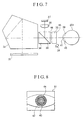
- FIG. 7 is a sectional view of the main parts of the third embodiment.
- an image of an object to be photographed is formed on a focusing screen 31 by a photographic lens (not shown).
- a pentagonal prism 32 laterally reverses and erects the image, which is observed through an eyepiece lens 33.
- a dichroic prism 34 has a cemented surface 35 that transmits the visual light but reflects an infrared light which cannot be perceived by the observer, constituting an optical unit of the eyeball-characteristic (visual line) detecting system together with an image forming lens 36, a light receiving element 37 such as area sensor and a light-emitting diode 38.
- the light-emitting diode 38 emits an infrared light of that nature which undergoes reflection from the cemented surface 35 of the dichroic prism 34. To the observer looking through the viewfinder, this light is invisible when illuminating his or her eyeball 201 by light projection means (not shown).
- the eyeball 201 has a cornea 39, an iris 40 and a pupil 41.
- the third embodiment although using the dichroic prism 34, insures that, because its cemented surface 35 has a spectral characteristic that reflects the infrared light but completely transmits the visible light, the object image on the focusing screen 31 the observer views as the laterally reverse, erected image through the pentagonal prism 32 can retain the same brightness as in the conventional camera.
- the light emitted from the light-emitting diode 38 is projected by a projection lens or like means (not shown) onto the eyeball 201.
- the reflected light from the cornea 39 and iris 40 passes through the eyepiece lens 33 in the reverse direction to that with the light coming from the focusing screen 31 and going to be observed. It then reflects from the cemented surface 35 in the dichroic prism 34 upward, and then passes through the image forming lens 36, by which information concerning the eyeball, for example, Purkinje image, is formed on the light receiving element 37. Therefore, the eyepiece lens 33 and the dichroic prism 34 are used as the common members in both of the viewfinder optical system and the optical system for detecting the visual line of the eyeball 201.
- Fig. 8 is a top view of the image receiving surface of the light receiving element 37, schematically showing what images about the eyeball 201 are cast thereon at this time.
- images 42 and 43 are of the iris 40 and pupil 41, respectively.
- An image of the light-emitting diode 38 is formed with the light reflecting from the cornea 39 of Fig. 7, constituting a first Purkinje image 44.
- the visual line of the observer is detected by a method known in the art.
- this detecting method use may be made of that disclosed in, for example, Japanese Laid-Open patent Application No. Sho 61-172552.
- the image signal from the light receiving element 37 is processed to find the center of the pupil image 43 and the location of the first Purkinje image 44. From the relationship between their current positions, which direction the observer looks to is detected.
- At least the closer surface 45 of the eyepiece lens 33 of Fig. 7 to the observer is provided with an antifogging coating.
- Another coating of such property may be applied to the inner surface 46 of the eyepiece lens 33. If so, the inside fogging resulting from the change of the ambient temperature also can be prevented well.
- the antifogging coating may be applied to not only the eyepiece lens 33 but also other members such as dichroic prism 34 and image forming lens 36. According to this, the accuracy of detection can be prevented from lowering due to the fogging. Further, the light receiving element 37 and the optical parts through which the light from the light-emitting diode 38 travels may be given the antifogging coating likewise.
- the antifogging coating in the third embodiment use can be made of what the principle of hydrophileness, water repellence or water absorption is applied to.
- the coating which, as described in the first and second embodiments, has the property of absorbing water in producing the antifogging effect. This is because the hydrophilic one lets a thin film of water be left on the surface and the water repellent one is difficult to remove the dewdrops completely. In either case, the optical performance is caused to deteriorate.
- the water absorptive coating diminishes dewdrops as soon as they appear, so that it is most excellent in the point of view of the good stability of optical performance.
- antifogging coating of water absorptiveness to make up a specific example of the antifoggy agent is similar to those shown in the first and second embodiments. So, the description thereof is omitted here.
- the antifogging coating may be also given the antireflection property like that in the first and second embodiments.
- the antireflection coating has such characteristics that not only the light transmission through the viewfinder of the camera is improved but also the electrical signal representing the detected visual line is deprived of noises resulting from the ghost and flare. That is, even for the infrared light from the light-emitting diode 38, a sufficient antireflection effect has to be produced.
- the visual line is detected in good results when the reflectance for the wavelength of the light-emitting diode of the antifogging coating is limited to not more than 2%. On consideration of the situation that, as the observer wears glasses, strong unnecessary light rays are liable to arise, the reflectance must be further reduced to 1% or lower.
- Fig. 9 is a sectional view of the main parts of a fourth embodiment of the invention, where the same reference numerals as those of Fig. 7 are used to denote the same elements.
- the fourth embodiment is different from the third embodiment of Fig. 7 in a point that a protection member 47 in the form of a parallel flat plate is provided on the observer side of the eyepiece lens 33 and at least one of its surfaces, namely, the closer surface 48 to the observer and the surface 49 of the object side.
- a protection member 47 in the form of a parallel flat plate is provided on the observer side of the eyepiece lens 33 and at least one of its surfaces, namely, the closer surface 48 to the observer and the surface 49 of the object side.
- such a plate is selected to form the antifogging coating thereon, thus retaining the good surface accuracy.
- the substrate is a plate whose both surfaces are flat and parallel to each other, the size of the plate can be increased greatly. In the later process, it can be cut to necessary sizes. So, it is advantageous even in the point of view of the mass production.
- the protection member 47 may be built in an appropriate carrier, which is made releasably attachable to the coupling member for the diopter correcting lens or the like provided on the housing of the eyepiece lens of the camera. If so, the invention becomes applicable to the existing cameras having no antifogging coatings. In the situation where no antifogging effect is necessary, the carrier can be removed to elongate the eye relief. The viewfinder becomes more comfortable to look through.
- the eyeball characteristic to be detected includes not only the visual line of the observer mentioned in the foregoing embodiments, but also the degree of sight, the state of the eyeground and other factors that can be detected by the reflected light from the eyeball.
- At least one of the optical members constituting the optical system for detecting the characteristic of the eyeball of the observer is provided with an antifogging coating, thereby making it possible to achieve an eyeball-characteristic detecting system which can detect well the characteristic of the eyeball no matter how the ambient atmosphere and the environmental conditions may change, and to achieve an optical apparatus having the eyeball-characteristic detecting system.
- An eyeball-characteristic detecting system which has such characteristic features, or an observation optical system having the eyeball-characteristic detecting system, is possible to realize easily.
- An observation optical system whose eye relief is below 25 mm includes an eyepiece lens having a water absorptive antifogging coating applied on one surface thereof, and a member holding the eyepiece lens.
- an eyeball-characteristic detecting system includes a light source for illuminating the eyeball of an observer, a light receiving element arranged on detection of the reflected light from the eyeball through the eyepiece to produce a signal, an optical member positioned in the path of the light from the light source to the light receiving element and having an antifogging coating on one surface thereof, and a circuit receptive of the signal for detecting the characteristic of the eyeball.
Landscapes
- Physics & Mathematics (AREA)
- General Physics & Mathematics (AREA)
- Optics & Photonics (AREA)
- Chemical & Material Sciences (AREA)
- Chemical Kinetics & Catalysis (AREA)
- Lenses (AREA)
- Viewfinders (AREA)
Applications Claiming Priority (6)
| Application Number | Priority Date | Filing Date | Title |
|---|---|---|---|
| JP24097397 | 1997-09-05 | ||
| JP9240973A JPH1184473A (ja) | 1997-09-05 | 1997-09-05 | 観察光学系及びそれを有した光学機器 |
| JP240973/97 | 1997-09-05 | ||
| JP21397/98 | 1998-01-19 | ||
| JP10021397A JPH11197111A (ja) | 1998-01-19 | 1998-01-19 | 眼球特性検出系及びそれを用いた光学機器 |
| JP2139798 | 1998-01-19 |
Publications (2)
| Publication Number | Publication Date |
|---|---|
| EP0901036A1 true EP0901036A1 (de) | 1999-03-10 |
| EP0901036B1 EP0901036B1 (de) | 2003-04-09 |
Family
ID=26358450
Family Applications (1)
| Application Number | Title | Priority Date | Filing Date |
|---|---|---|---|
| EP98116673A Expired - Lifetime EP0901036B1 (de) | 1997-09-05 | 1998-09-03 | Optisches Beobachtungssystem und optisches Gerät unter Verwendung desselben |
Country Status (3)
| Country | Link |
|---|---|
| US (1) | US6055376A (de) |
| EP (1) | EP0901036B1 (de) |
| DE (1) | DE69813119T2 (de) |
Families Citing this family (7)
| Publication number | Priority date | Publication date | Assignee | Title |
|---|---|---|---|---|
| JP2003161805A (ja) * | 2001-08-10 | 2003-06-06 | Canon Inc | 光学物品、及び該光学物品を組み込んだ光学機器 |
| JP2003139903A (ja) * | 2001-08-10 | 2003-05-14 | Canon Inc | 光学物品、及び該光学物品を組み込んだ光学機器 |
| US7535498B2 (en) * | 2005-01-03 | 2009-05-19 | Cnoga Medical Ltd. | Electronic viewing device |
| CN1804714B (zh) * | 2005-01-12 | 2011-08-03 | 佳能株式会社 | 光学设备 |
| JP4974780B2 (ja) * | 2007-06-22 | 2012-07-11 | キヤノン株式会社 | 光学観察装置及び撮像装置 |
| DE102010050513A1 (de) * | 2010-11-08 | 2012-05-10 | Karl Storz Gmbh & Co. Kg | Verfahren zum Montieren eines Deckglases in einem Endoskop sowie Endoskop |
| US11520083B2 (en) * | 2017-12-19 | 2022-12-06 | Canon Kabushiki Kaisha | Member, imaging apparatus, and method for producing member |
Citations (5)
| Publication number | Priority date | Publication date | Assignee | Title |
|---|---|---|---|---|
| JPS57130022A (en) * | 1981-02-05 | 1982-08-12 | Minolta Camera Co Ltd | Viewfinder attachment |
| EP0657767A1 (de) * | 1993-10-29 | 1995-06-14 | Canon Kabushiki Kaisha | Gerät zur Erfassung der Blickrichtung |
| JPH07248401A (ja) * | 1994-03-08 | 1995-09-26 | Enshu Kogaku Seiki Kk | 光学機器用防曇接眼レンズ及びこの製法 |
| US5453809A (en) * | 1993-10-13 | 1995-09-26 | Fuji Photo Optical Co., Ltd. | Albada finder |
| EP0716051A2 (de) * | 1994-12-08 | 1996-06-12 | Tohru Yamamoto | Beschlaghindernde Beschichtungszusammensetzung, Gegenstand mit einer beschlaghindernden Beschichtung und Verfahren zu deren Herstellung |
Family Cites Families (2)
| Publication number | Priority date | Publication date | Assignee | Title |
|---|---|---|---|---|
| JPS61172552A (ja) * | 1985-01-28 | 1986-08-04 | 株式会社トプコン | 視線方向検出装置 |
| US5570156A (en) * | 1991-08-26 | 1996-10-29 | Canon Kabushiki Kaisha | Camera utilizing detection of visual line |
-
1998
- 1998-09-01 US US09/145,209 patent/US6055376A/en not_active Expired - Lifetime
- 1998-09-03 DE DE69813119T patent/DE69813119T2/de not_active Expired - Lifetime
- 1998-09-03 EP EP98116673A patent/EP0901036B1/de not_active Expired - Lifetime
Patent Citations (5)
| Publication number | Priority date | Publication date | Assignee | Title |
|---|---|---|---|---|
| JPS57130022A (en) * | 1981-02-05 | 1982-08-12 | Minolta Camera Co Ltd | Viewfinder attachment |
| US5453809A (en) * | 1993-10-13 | 1995-09-26 | Fuji Photo Optical Co., Ltd. | Albada finder |
| EP0657767A1 (de) * | 1993-10-29 | 1995-06-14 | Canon Kabushiki Kaisha | Gerät zur Erfassung der Blickrichtung |
| JPH07248401A (ja) * | 1994-03-08 | 1995-09-26 | Enshu Kogaku Seiki Kk | 光学機器用防曇接眼レンズ及びこの製法 |
| EP0716051A2 (de) * | 1994-12-08 | 1996-06-12 | Tohru Yamamoto | Beschlaghindernde Beschichtungszusammensetzung, Gegenstand mit einer beschlaghindernden Beschichtung und Verfahren zu deren Herstellung |
Non-Patent Citations (2)
| Title |
|---|
| PATENT ABSTRACTS OF JAPAN vol. 006, no. 229 (P - 155) 16 November 1982 (1982-11-16) * |
| PATENT ABSTRACTS OF JAPAN vol. 096, no. 001 31 January 1996 (1996-01-31) * |
Also Published As
| Publication number | Publication date |
|---|---|
| DE69813119D1 (de) | 2003-05-15 |
| DE69813119T2 (de) | 2004-02-19 |
| EP0901036B1 (de) | 2003-04-09 |
| US6055376A (en) | 2000-04-25 |
Similar Documents
| Publication | Publication Date | Title |
|---|---|---|
| JP2950546B2 (ja) | 視線検出装置及び視線検出装置を有するカメラ | |
| US6055376A (en) | Observation optical system and optical apparatus having the same | |
| JPH07152068A (ja) | ファインダー装置 | |
| JP4148700B2 (ja) | 目画像撮像装置 | |
| US6830346B2 (en) | Optical element and optical equipment incorporating the same | |
| US6327430B1 (en) | Camera having antifogging film | |
| JPH1184473A (ja) | 観察光学系及びそれを有した光学機器 | |
| US6932482B2 (en) | Fog prevention and antireflection optical element and optical equipment incorporating the same | |
| JP2000249820A (ja) | フィルターおよびレンズ鏡筒 | |
| JPH06138369A (ja) | 視線検出装置 | |
| JP2009153676A (ja) | 前眼部断面撮影装置 | |
| JPH11197111A (ja) | 眼球特性検出系及びそれを用いた光学機器 | |
| JPH08179400A (ja) | ファインダ光学系及びその反転光学系 | |
| JP3774528B2 (ja) | 一眼レフカメラのファインダ | |
| US5502523A (en) | Inverted Galilean finder for camera | |
| JPH11194252A (ja) | カメラ | |
| JP2582499Y2 (ja) | カメラのファインダー光学系 | |
| JP2004333937A (ja) | ファインダー光学系及びそれを備えたカメラ | |
| JPH09251105A (ja) | 複合ミラーおよびその製造方法ならびに前記複合ミラーを用いた観察装置 | |
| JPH09269527A (ja) | 視線検出手段を有したファインダー系 | |
| JPH0618343Y2 (ja) | 屋根型反射鏡 | |
| WO2001071404A1 (en) | Optical device | |
| JPH04138431A (ja) | 視線検出手段を有したカメラ | |
| JP6679963B2 (ja) | ハーフミラー面を有する光学素子及びそれを用いた光学機器 | |
| JPS627294Y2 (de) |
Legal Events
| Date | Code | Title | Description |
|---|---|---|---|
| PUAI | Public reference made under article 153(3) epc to a published international application that has entered the european phase |
Free format text: ORIGINAL CODE: 0009012 |
|
| AK | Designated contracting states |
Kind code of ref document: A1 Designated state(s): DE FR GB IT NL |
|
| AX | Request for extension of the european patent |
Free format text: AL;LT;LV;MK;RO;SI |
|
| 17P | Request for examination filed |
Effective date: 19990805 |
|
| AKX | Designation fees paid |
Free format text: DE FR GB IT NL |
|
| 17Q | First examination report despatched |
Effective date: 20000505 |
|
| GRAG | Despatch of communication of intention to grant |
Free format text: ORIGINAL CODE: EPIDOS AGRA |
|
| GRAG | Despatch of communication of intention to grant |
Free format text: ORIGINAL CODE: EPIDOS AGRA |
|
| GRAH | Despatch of communication of intention to grant a patent |
Free format text: ORIGINAL CODE: EPIDOS IGRA |
|
| GRAH | Despatch of communication of intention to grant a patent |
Free format text: ORIGINAL CODE: EPIDOS IGRA |
|
| GRAA | (expected) grant |
Free format text: ORIGINAL CODE: 0009210 |
|
| AK | Designated contracting states |
Designated state(s): DE FR GB IT NL |
|
| PG25 | Lapsed in a contracting state [announced via postgrant information from national office to epo] |
Ref country code: NL Free format text: LAPSE BECAUSE OF FAILURE TO SUBMIT A TRANSLATION OF THE DESCRIPTION OR TO PAY THE FEE WITHIN THE PRESCRIBED TIME-LIMIT Effective date: 20030409 Ref country code: IT Free format text: LAPSE BECAUSE OF FAILURE TO SUBMIT A TRANSLATION OF THE DESCRIPTION OR TO PAY THE FEE WITHIN THE PRESCRIBED TIME-LIMIT;WARNING: LAPSES OF ITALIAN PATENTS WITH EFFECTIVE DATE BEFORE 2007 MAY HAVE OCCURRED AT ANY TIME BEFORE 2007. THE CORRECT EFFECTIVE DATE MAY BE DIFFERENT FROM THE ONE RECORDED. Effective date: 20030409 Ref country code: FR Free format text: LAPSE BECAUSE OF FAILURE TO SUBMIT A TRANSLATION OF THE DESCRIPTION OR TO PAY THE FEE WITHIN THE PRESCRIBED TIME-LIMIT Effective date: 20030409 |
|
| REG | Reference to a national code |
Ref country code: GB Ref legal event code: FG4D |
|
| NLV1 | Nl: lapsed or annulled due to failure to fulfill the requirements of art. 29p and 29m of the patents act | ||
| PG25 | Lapsed in a contracting state [announced via postgrant information from national office to epo] |
Ref country code: GB Free format text: LAPSE BECAUSE OF NON-PAYMENT OF DUE FEES Effective date: 20030903 |
|
| PLBE | No opposition filed within time limit |
Free format text: ORIGINAL CODE: 0009261 |
|
| STAA | Information on the status of an ep patent application or granted ep patent |
Free format text: STATUS: NO OPPOSITION FILED WITHIN TIME LIMIT |
|
| EN | Fr: translation not filed | ||
| 26N | No opposition filed |
Effective date: 20040112 |
|
| GBPC | Gb: european patent ceased through non-payment of renewal fee | ||
| PGFP | Annual fee paid to national office [announced via postgrant information from national office to epo] |
Ref country code: DE Payment date: 20140930 Year of fee payment: 17 |
|
| REG | Reference to a national code |
Ref country code: DE Ref legal event code: R119 Ref document number: 69813119 Country of ref document: DE |
|
| PG25 | Lapsed in a contracting state [announced via postgrant information from national office to epo] |
Ref country code: DE Free format text: LAPSE BECAUSE OF NON-PAYMENT OF DUE FEES Effective date: 20160401 |