EP0901092A2 - Kartenleser - Google Patents
Kartenleser Download PDFInfo
- Publication number
- EP0901092A2 EP0901092A2 EP98116800A EP98116800A EP0901092A2 EP 0901092 A2 EP0901092 A2 EP 0901092A2 EP 98116800 A EP98116800 A EP 98116800A EP 98116800 A EP98116800 A EP 98116800A EP 0901092 A2 EP0901092 A2 EP 0901092A2
- Authority
- EP
- European Patent Office
- Prior art keywords
- card
- magnetic head
- data
- card reader
- reading
- Prior art date
- Legal status (The legal status is an assumption and is not a legal conclusion. Google has not performed a legal analysis and makes no representation as to the accuracy of the status listed.)
- Granted
Links
Images


Classifications
-
- G—PHYSICS
- G06—COMPUTING OR CALCULATING; COUNTING
- G06K—GRAPHICAL DATA READING; PRESENTATION OF DATA; RECORD CARRIERS; HANDLING RECORD CARRIERS
- G06K7/00—Methods or arrangements for sensing record carriers, e.g. for reading patterns
- G06K7/08—Methods or arrangements for sensing record carriers, e.g. for reading patterns by means detecting the change of an electrostatic or magnetic field, e.g. by detecting change of capacitance between electrodes
- G06K7/082—Methods or arrangements for sensing record carriers, e.g. for reading patterns by means detecting the change of an electrostatic or magnetic field, e.g. by detecting change of capacitance between electrodes using inductive or magnetic sensors
- G06K7/083—Methods or arrangements for sensing record carriers, e.g. for reading patterns by means detecting the change of an electrostatic or magnetic field, e.g. by detecting change of capacitance between electrodes using inductive or magnetic sensors inductive
- G06K7/084—Methods or arrangements for sensing record carriers, e.g. for reading patterns by means detecting the change of an electrostatic or magnetic field, e.g. by detecting change of capacitance between electrodes using inductive or magnetic sensors inductive sensing magnetic material by relative movement detecting flux changes without altering its magnetised state
Definitions
- the present invention relates to a card reader for reading and erasing the data written on a magnetic stripe of a magnetic card.
- Data on a magnetic stripe of a magnetic card has been recorded in accordance with a certain format specified by a system in which the card is used.
- a certain format specified by a system in which the card is used usually, an ID number for identifying the card or holder of the card, validity date, the highest amount available and such other monetary information are written in a certain specific region of the data format.
- the card reader When a card is inserted in a card reader, the card reader reads data written in the card to be transmitted to a computer of the system. If the system is under an on-the-line control of the computer, data of the card is immediately analyzed and the ID number and other written contents are compared to make sure the card is theft-related or not, or the card is a one that has been issued through a due procedure or a one that has not been duly issued. In case the card is a pre-paid card or other cards having such other functions, the system confirms whether or not the card is a card that has once been used for an entire amount.
- a card reader in accordance with the present invention not only reads and confirms data recorded in a magnetic stripe, but it also has a function to destroy or erase a card, which could otherwise be put on an unjustifiable use.
- the card reader may be fabricated at an inexpensive cost, but it performs the above-described functions in a simple and easy manner.
- Conventional means for erasing the data recorded in a magnetic stripe of a card includes the use of a card reader equipped with both a recording magnetic head and a reading magnetic head, and the use of a card reader equipped with a combination type magnetic head consisted of a recording core and a reading core; thereby writing any new data on top of an already-written data by supplying an electric current to the recording coil.
- the card reader/writers equipped with both a magnetic head for recording and a magnetic head for reading, or the card reader/writers equipped with a combination type magnetic head having a recording core and a reading core have a problem with them that their overall dimensions are large and the cost goes substantially high.
- the previous data may be completely erased because the over-writing of data is conducted by the reading core that has a width identical to that of recording track.
- this method is easily affected by an azimuth loss caused by a matching error in the azimuth (angle ) between the gap of the core of magnetic head and the magnetic flux transition section recorded in the magnetic stripe of a card; such a drawback results from the use of the reading magnetic head having a reading core of broader width as compared with that of an ordinary reading magnetic head.
- the present invention presents a compact and inexpensive card reader of high read out function, which is provided with an additional function of reliably destroying/erasing the data recorded in a magnetic stripe of a card.
- a first card reader in accordance with the present invention comprises a main body of card reader having a card path, and a playback magnetic head disposed to face said card path.
- the data recorded in said card is erased or a certain data is written in said card by said reading magnetic head traversing obliquely across the magnetic stripe of said card with an electric current supplied to coil of said reading magnetic head.
- a second card reader in accordance with the present invention comprises a card path whose width is broader than the length of the shorter side of a card, transfer means for transferring a card within said card path, and load providing means for providing a card with a load im-balanced in the right-left relative to a direction of the longer side of a card.
- a third card reader in accordance with the present invention comprises a reading magnetic head which is mounted in a position so as the gap of head is in parallel with the magnetic flux transition section recorded in said magnetic stripe when the reading magnetic head is traversing obliquely across the magnetic stripe of a card.
- a fourth card reader in accordance with the present invention comprises siding means for making a card travel along the card path with the card sweeping a side wall of the card path; the siding means is put on operation when a card is being transferred for the data read out, while the siding means is kept out of operation when a card is being transferred for erasing the data recorded in said card or writing a certain specific data on said card.
- coil of the reading magnetic head is provided intermittently with an electric current of one single direction when erasing the data or writing a certain specific data in.
- coil of the reading magnetic head is provided with an unsaturated recording electric current when erasing the data or writing a certain specific data in.
- coil of the reading magnetic head is provided with an ever-changing electric current whose amplitude is varied at all times when erasing the data or writing a certain specific data in.
- the first card reader of the present invention erases the data recorded in said card or writes a certain specific data in said card in a manner that it traverses obliquely across the magnetic stripe of said card. As a result, the data may be destroyed/erased for the entire width of recording track.
- a card In the second card reader which provides a card with a load im-balanced in the right-left relative to a direction of the longer side of a card, a card is transferred with its corners on a diagonal respectively keeping in touch with the right and the left side walls of the card path.
- the card is thus transferred in an oblique positioning; therefore, said reading magnetic head proceeds obliquely across the magnetic stripe of said card.
- the data may be destroyed/erased for the entire width of recording track by said reading magnetic head erasing the data or writing a certain specific data in said card.
- the siding means is put on use to make a card travel through the card path with a side of the card keeping contact along a side wall of the card path, or a reference plane, while it is reading a card. Therefore, snaking motion of a card is suppressed for an improved accuracy in the track positioning and in the azimuth with respect to the gap of reading magnetic head. Thus the data stored in the magnetic stripe of said card may be read out correctly with a high reliability. On the other hand, when erasing the stored data or writing a certain specific data a card is transferred with the siding means out of operation.
- the reading magnetic head proceeds obliquely across the magnetic stripe of said card, as a result of effect of said im-balanced load given to the card. So, the data may be destroyed/erased for the entire width of recording track by said reading magnetic head erasing the data or writing a certain specific data in said card.
- the erasing of data or writing of a certain specific data is conducted by providing coil of the reading magnetic head intermittently with an electric current of one single direction, a turbulence of magnetization is caused on the magnetic stripe at a moment when the electric current flows into and when it makes an instantaneous interruption, and an interference is generated on the wave-form at the read out.
- the data may be destroyed/erased without fail.
- the reading core completely coincides with the width of the track of declined magnetization while reading out the data of declined magnetization, the data can not be read out correctly because the output is low; if said reading core is positioned on both a track of the declined magnetization and a track of non-declined magnetisation, the data in the track of declined magnetization appears as a noise and is overlapped on a read out signal, rendering correct reading of data difficult. Thus the data may be destroyed/erased without fail.
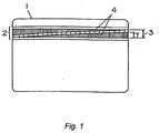
- FIG. 1 shows a state of data on a magnetic stripe of a card, after a stored data is erased or a certain specific data is written in by a card reader in accordance with a first embodiment of the present invention.
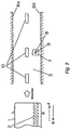
- Fig. 2 is a cross sectional view showing a structure of a key portion of a card reader in accordance with a first embodiment of the present invention.
- Fig.3 shows a state of a card being transferred over a magnetic head in an invented card reader.
- Fig. 4 is a drawing used to show how the angle of inclination of a card is calculated in an invented card reader.
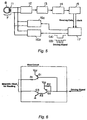
- Fig. 5 is a block diagram of circuits in an invented card reader.
- Fig. 6 is a circuit diagram showing the bias circuit contained in the Fig.5 block diagram.
- numeral 1 denotes a card, which is transferred in a card path 5 by a transfer roller 10.
- the width of card path 5 is broader than the length of the narrower side of card 1.
- Numeral 7 denotes an ordinary reading magnetic head having a reading core 8 whose width is narrower as compared with the width 3 of a recording track, which head is disposed in a position so as a card is provided with a load im-balanced in the right-left relative to a direction of the longer side of a card, at the same time an appropriate azimuth is secured with.
- the reading magnetic head 7 is wound around with a coil 11 in the reading core 8.
- a voltage induced in the coil 11 is amplified by an amplifier 12 to be delivered to a zero-crossing detector 14 via a differentiator, or an integrator, 13.
- Numeral 15 represents a demodulator, which demodulates a signal delivered from the zero-crossing detector 14 into a read out data and a clock.
- Numeral 17 is a control unit which is consisted of a central processing unit (CPU), etc. for controlling the whole card reader, including processing of read out data delivered from zero-crossing detector 14, operation of bias circuits 16a, 16b for magnetically exciting the reading magnetic head 7.
- CPU central processing unit
- card 1 is held between the transfer roller 10 and a pressure roller (not shown) provided to encounter the transfer roller 10, and is transferred for the data read out in the direction F indicated with an arrow symbol.
- a pressure roller not shown
- friction against the reading magnetic head 7 creates a retarding force along a longer side R of the card 1, while a longer side L of the card 1 is kept driven towards the direction F by the transfer force.
- the card 1 is driven to take an oblique position as shown in Fig. 3, with two corners 30a, 30b on a diagonal keeping in touch with the left and the right side walls 6a, 6b, respectively, of the card path 5.
- This state continues until the card 1 passes through the reading magnetic head 7; therefore, the reading magnetic head 7, which is disposed at a certain distance from one side wall 6b of card path 5, proceeds obliquely across the magnetic stripe 2 of card 1.
- the angle of inclination of card 1 may be approximated based on a supposition that all the four-corners of the card are right-angled.
- the azimuth of gap 9 of the core of reading magnetic head 7 may be set to be identical to the angle of inclination of card 1 ( approximated as ⁇ ). By so doing, a stable read out operation may be expected without being affected by the azimuth loss.
- the value T is given, when conducting the writing using the reading core 8 of reading magnetic head 7 in order to cover the full range of the recording track width 3, as illustrated in Fig. 1. Then, the width W of card path 5 may be determined to the satisfaction of the above-mentioned Formula 3 and Formula 4.
- Fig. 6 shows a structure of bias circuits 16a, 16b for magnetically exciting the reading magnetic head 7.
- the control unit 17 shown in Fig. 5 delivers a driving signal of wave-form (A) to turn the bias circuit ON, and an electric current is supplied to coil 11 of reading magnetic head 7 under the regulation by resistivity value of a current restricting resistor R1. Therefore, whether providing a card with a saturated recording or an unsaturated recording against the magnetic coercivity force may be determined by applying different resistivity value to the current restricting resistor R1.
- the bias circuits 16a, 16b stay in the OFF state, or in a state equivalent to a state where the bias circuits are separated from the read out circuit; therefore, it does not affect the operation of an amplifier 12.
- the playback magnetic head 7 may be excited intermittently by providing the bias circuits 16a, 16b with a pulse driving signal (B) as shown in Fig. 5.
- a turbulence of magnetization is caused on the magnetic stripe 2 of magnetic card 1 at a moment when the electric current flows into and when it makes an instantaneous interruption, and an interference on the wave-form is created at the read out.
- the above described constitution is simpler than a circuit structure where an alternating current is supplied to the coil 11 of reading magnetic head 7; yet the data may be destroyed/erased without fail.
- data stored in the magnetic stripe 2 of card 1 may be declined in the magnetization, with the degree of declined magnetization varying from place to place, by putting the two bias circuits 16a and 16b, each of which circuits delivering different amount of electric current to coil 11 of reading magnetic head, into ON state alternately, ref. Fig. 5.
- the reading core 8 of reading magnetic head 7 inevitably steps on both a portion of the declined magnetization and a portion of the non-declined magnetization at a same time. Therefore, data in the portion of declined magnetization appears as a noise overlapped on a read out signal, and a correct read out of data turns out to be difficult. Thus the data may be destroyed/erased without fail.
- a friction between card and magnetic head has been utilized as means for providing a card with a load im-balanced in the right-left relative to a direction of the longer side of the card
- a different member other than magnetic head may of course be employed for providing a card with such a load.
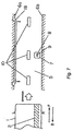
- Fig. 7 is a drawing used to describe a key part of a card reader in accordance with a second exemplary embodiment of the present invention.
- the point of difference as compared with the first embodiment includes that; the gap 9 of the core of reading magnetic head 7 is not inclined, and a guide plate 18 is provided within the card path 5 for guiding a card 1 to travel keeping contact along a side wall of the card path 5.
- the guide plate 18 is put on use to transfer the card with one of its sides keeping contact along a side wall, or the reference plane, in order to suppress the snaking of card during the transportation.
- a highly reliable reading may be carried out with respect to the accuracy in the track position and the azimuth of reading magnetic head 7.
- the card reader When the card 1 is found out to be a wrongful card or a card whose entire amounts have been totally used, the card reader operates, without putting the guide plate on use, in a same manner as in the first embodiment.
- the card reader performs a stable reading when reading a card, while on the other hand, destructs/erases data with a high reliability.
- a card 1 has been transferred by means of roller 10.
- roller 10 it is of course possible to transfer a card 1 by means of a belt.
- the destruction/erasing of data stored in the card 1 has been conducted while the card 1 is being transferred in a direction indicated by an arrow B in Fig. 2.
- the data may of course be destroyed/erased while the card 1 is being transferred in a same direction as in the reading out, indicated with an arrow F.
- the bias circuit for magnetically exciting reading magnetic head 7 has been provided for two circuits in the block diagram of Fig. 5; but, it may be constituted of one or any plural counts not less than two.
- bias circuit has been provided with an electric current of one single direction in Fig. 6, it may be an alternating current, if one does not mind somewhat more complicated circuit structure in the latter case.
- the timing of changing a driving signal to be supplied from the control unit 17 to bias circuits 16a, 16b may either be synchronized with clock signal of data stored in the card 1, or asynchronous.
- the data recorded in said card is erased or a certain data is written in said card in a manner to cross obliquely across the magnetic stripe of said card. Therefore, the data may be destroyed/erased for an entire region covering the full width of the recording track.
- a card is provided with a load im-balanced in the right-left with respect to a direction of the longer side of a card; as a result, the card is transferred obliquely with its two corners on a diagonal keeping contact with the right and the left side walls respectively of the card path. Therefore, the reading magnetic head proceeds obliquely across the magnetic stripe of said card.
- the data may be destroyed/erased for an entire region covering the full width of recording track by erasing the data or writing a certain specific data on said card with said reading magnetic head.
- the reading magnetic head is mounted in an oblique positioning so as its gap is in parallel with the magnetic reversal section recorded in said magnetic stripe. Therefore, the data stored in magnetic stripe of a card may be read out correctly without being affected by an output decrement due to azimuth loss or a wave-form interference.
- a fourth card reader in accordance with the present invention the snaking of card during transportation is suppressed by siding means which is put on operation during the read out for making a card travel along the card path with a side of the card sweeping a side wall of the card path.
- the siding means is kept out of the operation when a card is transferred for erasing the data recorded in said card or writing a certain specific data in said card; therefore, as a result of functioning of the load given on said card the reading magnetic head proceeds obliquely across the magnetic stripe of said card.
- the data may be destroyed/erased for an entire region covering the full width of the recording track by erasing the data or writing a certain specific data on said card with said reading magnetic head.
- coil of the reading magnetic head is provided intermittently with an electric current of one single direction when erasing the data or writing a certain specific data in.
- a turbulence of magnetization is caused on the magnetic stripe at a moment when the electric current comes into and when it makes an instantaneous interruption, and an interference on the wave-form is created at the read out.
- the data may be destroyed/erased without fail.
- coil of the reading magnetic head is provided with an unsaturated recording electric current for declining the data in the magnetization stored in the magnetic stripe of a card when erasing the data or writing a certain specific data in.
- an unsaturated recording electric current for declining the data in the magnetization stored in the magnetic stripe of a card when erasing the data or writing a certain specific data in.
- coil of the reading magnetic head is provided with an ever-changing electric current whose amplitude is varied at all times when erasing the data or writing a certain specific data in. This creates a number of regions of declined magnetization within the recording track width, yielding a same effect as in the sixth card reader.
Landscapes
- Engineering & Computer Science (AREA)
- Artificial Intelligence (AREA)
- Computer Vision & Pattern Recognition (AREA)
- Physics & Mathematics (AREA)
- General Physics & Mathematics (AREA)
- Theoretical Computer Science (AREA)
- Recording Or Reproducing By Magnetic Means (AREA)
- Digital Magnetic Recording (AREA)
- Control Of Vending Devices And Auxiliary Devices For Vending Devices (AREA)
Applications Claiming Priority (3)
| Application Number | Priority Date | Filing Date | Title |
|---|---|---|---|
| JP24069697A JP3419270B2 (ja) | 1997-09-05 | 1997-09-05 | カードリーダ |
| JP240696/97 | 1997-09-05 | ||
| JP24069697 | 1997-09-05 |
Publications (3)
| Publication Number | Publication Date |
|---|---|
| EP0901092A2 true EP0901092A2 (de) | 1999-03-10 |
| EP0901092A3 EP0901092A3 (de) | 2000-05-17 |
| EP0901092B1 EP0901092B1 (de) | 2005-11-30 |
Family
ID=17063349
Family Applications (1)
| Application Number | Title | Priority Date | Filing Date |
|---|---|---|---|
| EP98116800A Expired - Lifetime EP0901092B1 (de) | 1997-09-05 | 1998-09-04 | Kartenleser |
Country Status (4)
| Country | Link |
|---|---|
| EP (1) | EP0901092B1 (de) |
| JP (1) | JP3419270B2 (de) |
| DE (1) | DE69832561T2 (de) |
| ES (1) | ES2253799T3 (de) |
Cited By (3)
| Publication number | Priority date | Publication date | Assignee | Title |
|---|---|---|---|---|
| WO2004030925A1 (en) | 2002-10-04 | 2004-04-15 | Agfa-Gevaert | Method of making a lithographic printing plate precursor |
| GB2453918A (en) * | 2007-06-29 | 2009-04-29 | Paluku Lusi | Erasing magnetically held information |
| CN103513936A (zh) * | 2012-06-27 | 2014-01-15 | 巴法络记忆体股份有限公司 | 存储装置 |
Families Citing this family (1)
| Publication number | Priority date | Publication date | Assignee | Title |
|---|---|---|---|---|
| JP6058467B2 (ja) * | 2013-05-22 | 2017-01-11 | 日立オムロンターミナルソリューションズ株式会社 | 媒体処理装置、媒体処理方法、及び媒体処理プログラム |
Family Cites Families (8)
| Publication number | Priority date | Publication date | Assignee | Title |
|---|---|---|---|---|
| JPS6126905A (ja) * | 1984-07-16 | 1986-02-06 | Fuji Photo Film Co Ltd | 磁気記録媒体の消磁方法及び装置 |
| JPS61287009A (ja) * | 1985-06-13 | 1986-12-17 | Canon Inc | 回転ヘツド型記録装置 |
| JPS63197004A (ja) * | 1987-02-10 | 1988-08-15 | Csk Corp | 磁気カ−ドの情報記録方法 |
| JPH02281403A (ja) * | 1989-04-20 | 1990-11-19 | Toho Gas Co Ltd | 磁気カードのデータ消去方法 |
| JPH05314424A (ja) * | 1992-05-11 | 1993-11-26 | Matsushita Electric Ind Co Ltd | 磁気ヘッド |
| JPH06274703A (ja) * | 1993-01-25 | 1994-09-30 | Omron Corp | カード処理装置 |
| GB9525519D0 (en) * | 1995-12-14 | 1996-02-14 | At & T Global Inf Solution | A card reader system |
| JPH09326017A (ja) * | 1996-06-06 | 1997-12-16 | Sankyo Seiki Mfg Co Ltd | 磁気カードの不正使用防止方法及びその方法を利用したカードリーダ |
-
1997
- 1997-09-05 JP JP24069697A patent/JP3419270B2/ja not_active Expired - Fee Related
-
1998
- 1998-09-04 EP EP98116800A patent/EP0901092B1/de not_active Expired - Lifetime
- 1998-09-04 ES ES98116800T patent/ES2253799T3/es not_active Expired - Lifetime
- 1998-09-04 DE DE69832561T patent/DE69832561T2/de not_active Expired - Fee Related
Cited By (4)
| Publication number | Priority date | Publication date | Assignee | Title |
|---|---|---|---|---|
| WO2004030925A1 (en) | 2002-10-04 | 2004-04-15 | Agfa-Gevaert | Method of making a lithographic printing plate precursor |
| GB2453918A (en) * | 2007-06-29 | 2009-04-29 | Paluku Lusi | Erasing magnetically held information |
| CN103513936A (zh) * | 2012-06-27 | 2014-01-15 | 巴法络记忆体股份有限公司 | 存储装置 |
| CN103513936B (zh) * | 2012-06-27 | 2016-11-16 | 巴法络记忆体股份有限公司 | 存储装置 |
Also Published As
| Publication number | Publication date |
|---|---|
| DE69832561T2 (de) | 2006-06-08 |
| EP0901092A3 (de) | 2000-05-17 |
| JP3419270B2 (ja) | 2003-06-23 |
| ES2253799T3 (es) | 2006-06-01 |
| EP0901092B1 (de) | 2005-11-30 |
| DE69832561D1 (de) | 2006-01-05 |
| JPH1186205A (ja) | 1999-03-30 |
Similar Documents
| Publication | Publication Date | Title |
|---|---|---|
| US4466027A (en) | Digital tape erasure conditioning system | |
| EP0901092B1 (de) | Kartenleser | |
| US6073845A (en) | Recording medium on which information is recorded in intermittent pattern, and method of and apparatus for reproducing the information | |
| US6822827B1 (en) | Erasure techniques for magnetic tape media | |
| US4328519A (en) | Reading secure magnetic documents | |
| US5363251A (en) | Magnetic recorIding device | |
| US4593336A (en) | Magnetic recording | |
| US5568336A (en) | Magnetic reading device with alternating magnetic biasing means | |
| JPH0438045B2 (de) | ||
| JP2011249006A (ja) | 磁気ヘッド及び媒体処理装置 | |
| JP2565867B2 (ja) | カ−ド識別装置 | |
| JP3803192B2 (ja) | 真正さがチェックされる被検出物とこの被検出物の真正さをチェックするための処理装置 | |
| JPH09231301A (ja) | 磁気マーカおよびその読取方法 | |
| JP3836179B2 (ja) | 磁気マーカおよびその読取方法 | |
| JP2019053648A (ja) | カードリーダ | |
| JP2619054B2 (ja) | 磁気記録装置 | |
| JPH0863562A (ja) | 磁気記録媒体 | |
| JPS58159050U (ja) | 個人検証装置 | |
| GB2029074A (en) | Magnetic recording and playback | |
| JPH06266934A (ja) | 磁気情報読み取り装置 | |
| JPS63289693A (ja) | 磁気記録再生装置 | |
| JPH10149502A (ja) | 情報処理装置 | |
| JPS61163488A (ja) | 自動払戻し機 | |
| JPH06502041A (ja) | データ転送ヘッド | |
| JPH08153174A (ja) | 磁気カード不正防止方法及び磁気記録再生装置及び磁気媒体を使用するシステム装置 |
Legal Events
| Date | Code | Title | Description |
|---|---|---|---|
| PUAI | Public reference made under article 153(3) epc to a published international application that has entered the european phase |
Free format text: ORIGINAL CODE: 0009012 |
|
| AK | Designated contracting states |
Kind code of ref document: A2 Designated state(s): DE ES |
|
| AX | Request for extension of the european patent |
Free format text: AL;LT;LV;MK;RO;SI |
|
| PUAL | Search report despatched |
Free format text: ORIGINAL CODE: 0009013 |
|
| AK | Designated contracting states |
Kind code of ref document: A3 Designated state(s): AT BE CH CY DE DK ES FI FR GB GR IE IT LI LU MC NL PT SE |
|
| AX | Request for extension of the european patent |
Free format text: AL;LT;LV;MK;RO;SI |
|
| 17P | Request for examination filed |
Effective date: 20001006 |
|
| AKX | Designation fees paid |
Free format text: DE ES |
|
| 17Q | First examination report despatched |
Effective date: 20040826 |
|
| GRAP | Despatch of communication of intention to grant a patent |
Free format text: ORIGINAL CODE: EPIDOSNIGR1 |
|
| GRAS | Grant fee paid |
Free format text: ORIGINAL CODE: EPIDOSNIGR3 |
|
| GRAA | (expected) grant |
Free format text: ORIGINAL CODE: 0009210 |
|
| AK | Designated contracting states |
Kind code of ref document: B1 Designated state(s): DE ES |
|
| REF | Corresponds to: |
Ref document number: 69832561 Country of ref document: DE Date of ref document: 20060105 Kind code of ref document: P |
|
| REG | Reference to a national code |
Ref country code: ES Ref legal event code: FG2A Ref document number: 2253799 Country of ref document: ES Kind code of ref document: T3 |
|
| PLBE | No opposition filed within time limit |
Free format text: ORIGINAL CODE: 0009261 |
|
| STAA | Information on the status of an ep patent application or granted ep patent |
Free format text: STATUS: NO OPPOSITION FILED WITHIN TIME LIMIT |
|
| PGFP | Annual fee paid to national office [announced via postgrant information from national office to epo] |
Ref country code: DE Payment date: 20061027 Year of fee payment: 9 |
|
| 26N | No opposition filed |
Effective date: 20060831 |
|
| PG25 | Lapsed in a contracting state [announced via postgrant information from national office to epo] |
Ref country code: DE Free format text: LAPSE BECAUSE OF NON-PAYMENT OF DUE FEES Effective date: 20080401 |
|
| REG | Reference to a national code |
Ref country code: ES Ref legal event code: FD2A Effective date: 20070905 |
|
| PG25 | Lapsed in a contracting state [announced via postgrant information from national office to epo] |
Ref country code: ES Free format text: LAPSE BECAUSE OF NON-PAYMENT OF DUE FEES Effective date: 20070905 |