EP0901238A2 - Annulateur d'écho - Google Patents
Annulateur d'écho Download PDFInfo
- Publication number
- EP0901238A2 EP0901238A2 EP98307064A EP98307064A EP0901238A2 EP 0901238 A2 EP0901238 A2 EP 0901238A2 EP 98307064 A EP98307064 A EP 98307064A EP 98307064 A EP98307064 A EP 98307064A EP 0901238 A2 EP0901238 A2 EP 0901238A2
- Authority
- EP
- European Patent Office
- Prior art keywords
- echo
- circuit
- telephone circuit
- transmit signal
- telephone
- Prior art date
- Legal status (The legal status is an assumption and is not a legal conclusion. Google has not performed a legal analysis and makes no representation as to the accuracy of the status listed.)
- Granted
Links
Images


Classifications
-
- H—ELECTRICITY
- H04—ELECTRIC COMMUNICATION TECHNIQUE
- H04B—TRANSMISSION
- H04B3/00—Line transmission systems
- H04B3/02—Details
- H04B3/20—Reducing echo effects or singing; Opening or closing transmitting path; Conditioning for transmission in one direction or the other
- H04B3/23—Reducing echo effects or singing; Opening or closing transmitting path; Conditioning for transmission in one direction or the other using a replica of transmitted signal in the time domain, e.g. echo cancellers
Definitions
- the present invention relates to an echo canceler for suppressing an echo of a received signal generated by impedance mismatching in an analog two-wire/four-wire conversion portion of a telephone circuit.
- the transfer function of the echo path it is possible to estimate the transfer function of the echo path in the case where a signal in the transmit direction is only the echo of the receive signal. In the case where the signal in the transmit direction contains a mixture of the echo of the receive signal and the transmit signal, however, the transfer function of the echo path cannot be estimated.
- the current state is a double talk state such as a state of mixed presence of the transmit signal and the receive signal, or a state of only the transmit signal. If the current state is the double talk state, the operation for estimating the transfer function is stopped.
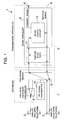
- FIG. 5 is a block diagram showing the schematic configuration of the inside of an echo canceler system adopting such a conventional echo canceler.
- An echo canceler system 100 shown in FIG. 5 includes an analog two-wire telephone set 101, an analog two-wire telephone set 101, an analog four-wire telephone set 102, a transmission apparatus 104 having an echo canceler 103, and an exchange 106 for conducting exchange and connection for the analog two-wire telephone set 101, the analog four-wire telephone set 102, and telephone circuits 105 via the transmission apparatus 104.
- this exchange 106 there are included a two-wire/four-wire conversion unit 107 connected to the analog two-wire telephone set 101 to conduct mutual two-wire/four-wire conversion for the transmit and receive signals, an exchange switch 108 for conducting switching connection among the two-wire/four-wire conversion unit 107, the analog four-wire telephone set 102, and the transmission apparatus 104, and a PB (push-button dial) signal transmitter 109 for transmitting a PB signal obtained from the analog two-wire telephone set 101 or the analog four-wire telephone set 102 to a circuit side exchange.
- PB push-button dial
- the echo canceler 103 includes an echo cancel circuit 110 for suppressing the echo of the receive signal contained in the transmit signal supplied from the analog two-wire telephone set 102.
- an echo canceler system 100 it is possible to suppress an echo of a receive signal in the echo cancel circuit 110 by estimating a transfer function of an echo path on the basis of the receive signal of the analog two-wire telephone set 101 and the echo of the receive signal, generating a pseudo echo on the basis of the estimated transfer function and the receive signal, and subtracting the pseudo echo from a transmit signal.
- the conventional echo canceler 103 has such a configuration that the operation of estimating the transfer function of the echo path is stopped if the current state is judged to be a double talk state.
- the transmit signal and the receive signal have similar frequency components, there is a fear that the current state is falsely judged not to be a double talk state although the current state is a double talk state. If in such a double talk state the transfer function of the echo path is estimated, an estimated value is disturbed and the speech quality of the transmit signal is degraded.
- the echo canceler 103 In the case where the echo canceler 103 is applied to a telephone circuit having no echo path, however, the current state is falsely judged not to be the double talk state although the current state is the double talk state. Therefore, the transfer function of the echo path which does not exist is estimated, a pseudo echo is generated, and the pseudo echo is subtracted from a transmit signal. Thus there is a fear that the degradation of the speech quality of the transmit signal may be greatly influenced.
- the caller of the analog two-wire telephone set 101 When originating a call from the analog two-wire telephone set 101 toward a telephone set of circuit side, the caller of the analog two-wire telephone set 101 unhooks the receiver of the telephone set 101 and obtains the dial tone from the exchange of the circuit side. And the caller presses the dial number of the telephone set of circuit side.
- this dial signal system is the PB system
- the analog two-wire telephone set 101 of the caller side transmits a PB signal representing dial numbers to the exchange 106.
- the exchange 106 temporarily stores this PB signal, and transmits the PB signal from the PB signal transmitter 109 included in the exchange 106 to the circuit side exchange via the transmission apparatus 104.
- JP-A-5-14242 discloses a method of controlling an echo canceler. This method is aimed to enable comfortable conversation even if the level of a voice signal changes extremely. However, this document does not disclose preventing speech quality degradation due to the false judgment of double talk.
- JP-A-5-218904 discloses a method of controlling an echo canceler. This method is aimed to solve the problem that the echo suppression effect is decreased when there exist bi-direction input signals having low frequency components. However, this document also does not disclose preventing speech quality degradation due to the false judgment of double talk.
- JP-A-9-148966 discloses an echo canceler in which the judgment of double talk is performed by a non-linear processor independently from an echo canceling unit. Therefore, even if the judgment of double talk in the echo canceling unit is often changed, the non-linear processor can work stably.
- an echo canceler according to the present invention has a different structure from the echo canceler according to this document.
- a first object of the present invention is to provide an echo canceler capable of being applied to a telephone circuit having no echo path and certainly improving the speech quality degradation of the transmit signal even if the double talk state is caused.
- a second object of the present invention is to provide an echo canceler capable of certainly preventing the signal quality of the PB signal from being degraded even if it is used in a double talk state.
- An echo canceler is an echo canceler for suppressing an echo of a receive signal contained in a transmit signal directed to a telephone circuit and transferring the transmit signal subjected to echo suppression to the telephone circuit
- the echo canceler comprises: a pseudo echo path including attenuation means for attenuating the receive signal supplied from the telephone circuit, delay means for delaying the receive signal attenuated by the attenuation means, and addition means for adding the receive signal delayed by the delay means to the transmit signal; and an echo cancel circuit for estimating a transfer function of the pseudo echo path on the basis of the receive signal supplied from the telephone circuit and the echo of the receive signal, generating a pseudo echo on the basis of a value of the estimation and the receive signal, subtracting the pseudo echo from the transmit signal passed through the pseudo echo path, and thereby transferring the transmit signal subjected to echo suppression to the telephone circuit.
- the pseudo echo path is an echo path provided simulatively and includes attenuation means for attenuating the receive signal supplied from the telephone circuit, delay means for delaying the receive signal attenuated by the attenuation means, and addition means for adding the receive signal delayed by the delay means to the transmit signal. Even if the current state is falsely judged not to be a double talk state although the current state is the double talk state, the echo cancel circuit conducts the operation of estimating the transfer function of the pseudo echo path.
- This echo cancel circuit estimates a transfer function of the pseudo echo path on the basis of the receive signal supplied from the telephone circuit and the echo of the receive signal, generates a pseudo echo on the basis of a value of the estimation and the receive signal, subtracts the pseudo echo from the transmit signal, and thereby transfers the transmit signal subjected to echo suppression to the telephone circuit.
- the echo canceler estimates the transfer function of the pseudo echo path on the basis of the receive signal obtained from the telephone circuit and the echo of the receive signal, generates a pseudo echo on the basis of a value thus estimated and the receive signal, and subtracts this pseudo echo from the transmit signal. If the echo canceler is applied to a telephone circuit having no echo path and even if the double talk state is caused, therefore, the estimated value of the transfer function of the pseudo echo path is not largely disturbed by false judgment of double talk, because the pseudo echo path is always present. As a result, the speech quality degradation of the transmit signal can be certainly prevented.
- An echo canceler is characterized in that, in addition to the configuration of the echo canceler according to the first aspect, the echo canceler comprises: talking determining means for determining whether a usage state of a telephone circuit is a talking state; changeover connection means for conducting changeover connection of the pseudo echo path with the cancel circuit; and control means responsive to judging in the talking determining means the usage state of the telephone circuit to be the talking state, for controlling the changeover connection means so as to connect the pseudo echo path with the echo cancel circuit in order to transfer the transmit signal to the telephone circuit via the echo cancel circuit.
- the talking determining means monitors the usage state of the telephone circuit. For example, the talking determining means determines whether the usage state of the telephone circuit is the talking state on the basis of states of SS supplied from the exchange and SR supplied from the telephone circuit.
- the changeover connection means corresponds to a switch for conducting the changeover connection of the pseudo echo path with the echo cancel circuit.
- the changeover connection means transfers the transmit signal to the telephone circuit via the echo cancel circuit, or transfers the transmit signal to the telephone circuit without passing it through the echo cancel circuit.
- the control means controls the changeover connection means located between the pseudo echo path and the echo cancel circuit on the basis of a result of the determining conducted by the talking determining means. For example, if the talking determining means judges the usage state of the telephone circuit to be the talking state, the control means controls the changeover connections so as to connect the pseudo echo path with the echo cancel circuit and transfer the transmit signal to the telephone circuit via the echo cancel circuit.
- the echo canceler In the echo canceler according to the second aspect of the present invention, if the usage state of the telephone circuit is judged to be a talking state, then the pseudo echo path is connected with the echo cancel circuit, and the transmit signal is transferred to the telephone circuit via the echo cancel circuit. In other words, at the time of call origination when the usage state of the telephone circuit is not the talking state, the PB signal which is the transmit signal is transferred to the telephone circuit without being passed through the echo cancel circuit. In addition to the above described effect of the echo canceler according to the first aspect, therefore, it becomes possible to certainly prevent the echo cancel circuit from degrading the signal quality of the PB signal.
- An echo canceler is an echo canceler for suppressing an echo of a receive signal contained in a transmit signal directed to a telephone circuit and transferring the transmit signal subjected to echo suppression to the telephone circuit, characterized in that the echo canceler comprises: an echo cancel circuit for generating a pseudo echo on the basis of the receive signal supplied from the telephone circuit and the echo of the receive signal, subtracting the pseudo echo from the transmit signal directed to the telephone circuit, and transferring the transmit signal subjected to echo suppression to the telephone circuit; talking determining means for determining whether a usage state of a telephone circuit is a talking state; changeover connection means for conducting changeover connection of the telephone circuit with the echo cancel circuit; and control means responsive to judging in the talking determining means the usage state of the telephone circuit to be the talking state, for controlling the changeover connection means so as to connect the echo cancel circuit with the telephone circuit in order to transfer the transmit signal to the telephone circuit via the echo cancel circuit.
- the changeover connection means corresponds to a switch for conducting the changeover connection of the telephone circuit with the echo cancel circuit.
- the changeover connection means transfers the transmit signal to the telephone circuit via the echo cancel circuit, or transfers the transmit signal to the telephone circuit without passing it through the echo cancel circuit.
- the control means controls the changeover connection means located between the echo cancel circuit and the telephone circuit on the basis of a result of the determining conducted by the talking determining means. For example, if the talking determining means judges the usage state of the telephone circuit to be the talking state, the control means controls the changeover connections of the telephone circuit with the echo cancel circuit and transfer the transmit signal to the telephone circuit via the echo cancel circuit.
- the echo canceler therefore, if the usage state of the telephone circuit is judged to be a talking state, then the pseudo echo path is connected with the echo cancel circuit, and the transmit signal is transferred to the telephone circuit via the echo cancel circuit.
- the PB signal which is the transmit signal is transferred to the telephone circuit without being passed through the echo cancel circuit. Therefore, it becomes possible to certainly prevent the echo cancel circuit from degrading the signal quality of the PB signal.
- FIG. 1 is a block diagram showing the schematic configuration of the inside of an echo canceler system shown in a first embodiment.
- FIG. 2 is a block diagram showing the schematic configuration of the inside of an echo canceler which is a main part of an echo canceler system shown in the first embodiment.
- An echo canceler system 1 shown in FIG. 1 includes an analog two-wire telephone set 2, an analog two-wire telephone set 3, a transmission apparatus 5 having an echo canceler 4, and an exchange 7 for conducting exchange and connection for the analog two-wire telephone set 2, the analog four-wire telephone set 3, and telephone circuits 6 via the transmission apparatus 5.
- a two-wire/four-wire conversion unit 8 connected to the analog two-wire telephone set 2 to conduct mutual two-wire/four-wire conversion for the transmit and receive signals, an exchange switch 9 for conducting switching connection among the two-wire/four-wire conversion unit 8, the analog four-wire telephone set 3, and the transmission apparatus 5, and a PB signal transmitter 10 for transmitting a PB signal obtained from the analog two-wire telephone set 2 or the analog four-wire telephone set 3 to a circuit side exchange.
- the echo canceler 4 included in the transmission apparatus 5 includes a receive signal input terminal 4a connected to the telephone circuit 6 to input a receive signal, a receive signal output terminal 4b connected to the exchange 7 to output the receive signal, a transmit signal output terminal 4d connected to the telephone circuit 6 to output the transmit signal, a false echo path 11 for attenuating the receive signal obtained from the receive signal input terminal 4a, delaying the receive signal thus attenuated, and adding the receive signal thus delayed to the transmit signal, and an echo cancel circuit 12 for suppressing an echo contained in the transmit signal and transferring the transmit signal thus subjected to echo suppression to the telephone circuit 6.
- the echo cancel circuit 12 estimates a transfer function of a pseudo echo path 11 on the basis of the receive signal obtained from the telephone circuit 6 and an echo of the receive signal, generates a pseudo echo on the basis of a value thus estimated and the receive signal, subtracts this pseudo echo from the transmit signal passed through the pseudo echo path 11, and thereby transfers the transmit signal subjected to echo suppression to the telephone circuit 6.
- the echo cancel circuit 12 estimates the transfer function of the pseudo echo path 11. Even if the echo cancel circuit 12 falsely judges the current state not to be a double talk state in spite of the double talk state, the influence over the speech quality of the transmit signal is slight because the pseudo echo path 11 exists.
- the echo cancel circuit 12 estimates the transfer function of the echo path between the two-wire/four-wire conversion unit 8 and the pseudo echo path 11. Even if the echo cancel circuit 12 falsely judges the current state not to be a double talk state in spite of the double talk state, the influence over the speech quality of the transmit signal is slight because the pseudo echo path 11 exists.
- the echo cancel circuit 12 estimates the transfer function of the pseudo echo path 11 on the basis of the receive signal obtained from the telephone circuit 6 and the echo of the receive signal, generates a pseudo echo on the basis of a value thus estimated and the receive signal, and subtracts this pseudo echo from the transmit signal. If the echo canceler system is applied to a telephone circuit 6 having no echo path and even if the double talk state is caused, therefore, the estimated value of the transfer function of the pseudo echo path 1 is not largely disturbed by false judgment of double talk because the pseudo echo path 11 is always present. As a result, the speech quality degradation of the transmit signal can be certainly improved.
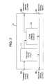
- FIG. 3 is a block diagram showing the schematic configuration of the inside of an echo canceler system shown in a second embodiment.
- FIG. 4 is a block diagram showing the schematic configuration of the inside of an echo canceler which is a main part of an echo canceler system shown in the second embodiment.
- An echo canceler system 20 shown in FIG. 3 is characterized in that the pseudo echo path 11 is not provided within an echo canceler 21, but the echo canceler 21 has a switch 22 for conducting changeover connection of the telephone circuit 6 with an echo cancel circuit 12.
- the analog two-wire telephone set 2 when originating a call from the analog two-wire telephone set 2 to a telephone set of the other party, the analog two-wire telephone set 2 obtains a dial tone from an exchange of the other party as a result of off-hook of the analog two-wire telephone set 2. In this state, a calling subscribed of the analog two-wire telephone set 2 depresses a dial number of a telephone set of the other party. In the case where the dial signaling system is the PB system, the analog two-wire telephone set 2 transmits the depressed PB signal to an exchange 7. The exchange 7 temporarily stores this PB signal and, in addition, transmits the PB signal to a transmission apparatus 5 via a PB signal transmitter 10.
- the transmit signal obtained from the transmit signal input terminal 4c is transferred to the telephone circuit of the telephone set of the other party via the echo cancel circuit 12.
- the echo cancel circuit 12 suppresses the echo of the receive signal contained in the transmit signal by answering or off-hook of the telephone set of the other party, and consequently the usage state becoming the talking state.
- the echo cancel circuit 12 if the usage state of the telephone circuit 6 is judged to be a talking state, then the echo cancel circuit 12 is connected with the telephone circuit 6, and the transmit signal is transferred to the telephone circuit 6 via the echo cancel circuit 12.
- the PB signal which is the transmit signal is transferred to the telephone circuit 6 without being passed through the echo cancel circuit 12. Therefore, the echo cancel circuit 12 does not affect the signal quality of the PB signal. It thus becomes possible to avoid problems such as uncompleted connection or mis-connection caused by the quality degradation of the PB signal.
- the echo canceler estimates the transfer function of the pseudo echo path on the basis of the receive signal obtained from the telephone circuit and the echo of the receive signal, generates a pseudo echo on the basis of a value thus estimated and the receive signal, and subtracts this pseudo echo from the transmit signal. If the echo canceler is applied to a telephone circuit having no echo path and even if the double talk state is caused, therefore, the estimated value of the transfer function of the pseudo echo path is not largely disturbed by false judgment of double talk, because the pseudo echo path is always present. As a result, the speech quality degradation of the transmit signal can be certainly improved.
- the echo canceler if the usage state of the telephone circuit is judged to be a talking state, then the pseudo echo path is connected with the echo cancel circuit, and the transmit signal is transferred to the telephone circuit via the echo cancel circuit.
- the PB signal which is the transmit signal is transferred to the telephone circuit without being passed through the echo cancel circuit. Therefore, it becomes possible to certainly prevent the echo cancel circuit from degrading the signal quality of the PB signal.
- the echo cancel circuit if the usage state of the telephone circuit is judged to be a talking state, then the echo cancel circuit is connected with the telephone circuit, and the transmit signal is transferred to the telephone circuit via the echo cancel circuit.
- the PB signal which is the transmit signal is transferred to the telephone circuit without being passed through the echo cancel circuit. Therefore, it becomes possible to certainly prevent the echo cancel circuit from degrading the signal quality of the PB signal.
Landscapes
- Engineering & Computer Science (AREA)
- Computer Networks & Wireless Communication (AREA)
- Signal Processing (AREA)
- Cable Transmission Systems, Equalization Of Radio And Reduction Of Echo (AREA)
- Interface Circuits In Exchanges (AREA)
Applications Claiming Priority (3)
| Application Number | Priority Date | Filing Date | Title |
|---|---|---|---|
| JP254105/97 | 1997-09-04 | ||
| JP25410597 | 1997-09-04 | ||
| JP25410597A JP3710606B2 (ja) | 1997-09-04 | 1997-09-04 | エコーキャンセラ |
Publications (3)
| Publication Number | Publication Date |
|---|---|
| EP0901238A2 true EP0901238A2 (fr) | 1999-03-10 |
| EP0901238A3 EP0901238A3 (fr) | 1999-10-20 |
| EP0901238B1 EP0901238B1 (fr) | 2005-07-27 |
Family
ID=17260301
Family Applications (1)
| Application Number | Title | Priority Date | Filing Date |
|---|---|---|---|
| EP98307064A Expired - Lifetime EP0901238B1 (fr) | 1997-09-04 | 1998-09-02 | Annulateur d'écho |
Country Status (7)
| Country | Link |
|---|---|
| US (1) | US6618479B1 (fr) |
| EP (1) | EP0901238B1 (fr) |
| JP (1) | JP3710606B2 (fr) |
| CN (1) | CN1213907A (fr) |
| CA (1) | CA2246757C (fr) |
| DE (1) | DE69830959T2 (fr) |
| ID (1) | ID20795A (fr) |
Families Citing this family (1)
| Publication number | Priority date | Publication date | Assignee | Title |
|---|---|---|---|---|
| US6351531B1 (en) * | 2000-01-21 | 2002-02-26 | Motorola, Inc. | Method and system for controlling echo cancellation using zero echo path, ringing, and off-hook detection |
Family Cites Families (15)
| Publication number | Priority date | Publication date | Assignee | Title |
|---|---|---|---|---|
| JPS5226973B2 (fr) * | 1973-01-19 | 1977-07-18 | ||
| US4144417A (en) | 1975-03-07 | 1979-03-13 | Kokusai Denshin Denwa Kabushiki Kaisha | Echo cancelling system |
| JPS56153850A (en) | 1980-04-28 | 1981-11-28 | Kokusai Denshin Denwa Co Ltd <Kdd> | Echo control system |
| JPS6053336A (ja) * | 1983-09-02 | 1985-03-27 | Nec Corp | 反響消去装置 |
| JPH01218131A (ja) * | 1988-02-25 | 1989-08-31 | Nec Corp | エコーキャンセラ制御システム |
| JP2520770B2 (ja) * | 1990-07-06 | 1996-07-31 | 富士通株式会社 | ハイブリッド回路 |
| JPH0483429A (ja) * | 1990-07-25 | 1992-03-17 | Fujitsu Ltd | 残留エコー抑圧方式 |
| JP2814777B2 (ja) | 1991-06-28 | 1998-10-27 | 松下電器産業株式会社 | エコーキャンセラ制御方法 |
| JP3147457B2 (ja) | 1992-02-04 | 2001-03-19 | 松下電器産業株式会社 | エコーキャンセラ制御法 |
| CN1232048C (zh) | 1994-05-06 | 2005-12-14 | 株式会社Ntt都科摩 | 回波消除器 |
| JP3395388B2 (ja) * | 1994-08-16 | 2003-04-14 | ソニー株式会社 | 信号適応処理装置及びエコー抑圧装置 |
| US5606550A (en) * | 1995-05-22 | 1997-02-25 | Hughes Electronics | Echo canceller and method for a voice network using low rate coding and digital speech interpolation transmission |
| JP3244416B2 (ja) | 1995-11-18 | 2002-01-07 | 松下電器産業株式会社 | エコーキャンセラ |
| JP3654470B2 (ja) * | 1996-09-13 | 2005-06-02 | 日本電信電話株式会社 | サブバンド多チャネル音声通信会議用反響消去方法 |
| US5920834A (en) * | 1997-01-31 | 1999-07-06 | Qualcomm Incorporated | Echo canceller with talk state determination to control speech processor functional elements in a digital telephone system |
-
1997
- 1997-09-04 JP JP25410597A patent/JP3710606B2/ja not_active Expired - Fee Related
-
1998
- 1998-09-01 US US09/144,463 patent/US6618479B1/en not_active Expired - Fee Related
- 1998-09-01 CA CA002246757A patent/CA2246757C/fr not_active Expired - Fee Related
- 1998-09-02 DE DE69830959T patent/DE69830959T2/de not_active Expired - Lifetime
- 1998-09-02 EP EP98307064A patent/EP0901238B1/fr not_active Expired - Lifetime
- 1998-09-04 ID IDP981197A patent/ID20795A/id unknown
- 1998-09-04 CN CN98118584A patent/CN1213907A/zh active Pending
Also Published As
| Publication number | Publication date |
|---|---|
| CA2246757A1 (fr) | 1999-03-04 |
| DE69830959T2 (de) | 2006-04-20 |
| DE69830959D1 (de) | 2005-09-01 |
| CN1213907A (zh) | 1999-04-14 |
| ID20795A (id) | 1999-03-04 |
| EP0901238A3 (fr) | 1999-10-20 |
| EP0901238B1 (fr) | 2005-07-27 |
| US6618479B1 (en) | 2003-09-09 |
| JPH1188922A (ja) | 1999-03-30 |
| JP3710606B2 (ja) | 2005-10-26 |
| CA2246757C (fr) | 2001-08-07 |
Similar Documents
| Publication | Publication Date | Title |
|---|---|---|
| US5353348A (en) | Double echo cancelling system | |
| US6052462A (en) | Double talk detection and echo control circuit | |
| US8750493B2 (en) | Method and system for stereo echo cancellation for VoIP communication systems | |
| US6665402B1 (en) | Method and apparatus for performing echo cancellation | |
| US5381474A (en) | Method of converging an echo canceller | |
| US7231036B2 (en) | Anti-howling circuit detecting howling from effect of predicted echo signal | |
| US6836547B2 (en) | Protecting an echo canceller against random transitions in echo paths | |
| CA2207461C (fr) | Affaiblissement d'equilibrage pour l'echo non constant pour poste telephonique mains libres | |
| EP0901238B1 (fr) | Annulateur d'écho | |
| CN1208518A (zh) | 消除通信系统中回声信号的方法及配置 | |
| JP2002280938A (ja) | エコーキャンセラ装置 | |
| JP3220979B2 (ja) | 音声スイッチ | |
| US6912281B2 (en) | Route delay sensitive echo cancellation | |
| EP0920172B1 (fr) | Méthode de commande d'un annuleur d'echo dans un canal de données | |
| KR100540943B1 (ko) | 서비스신호를검파하기위해에코제거기를구비한전화장치및서비스신호검파방법 | |
| US5898773A (en) | Telephone apparatus with call transfer function and with improved arrangement for hand-free operation | |
| US7734036B1 (en) | Dynamic attenuation method and apparatus for optimizing voice quality using echo cancellers | |
| JPS6364104B2 (fr) | ||
| JPH04185023A (ja) | エコーキャンセラ装置 | |
| JPH0346419A (ja) | 自動遅延キャンセラ装置 | |
| JPS61172471A (ja) | 会議通話用拡声電話機の廻り込み防止方式 | |
| JP3003383B2 (ja) | Pbxの音声品質保証装置 | |
| JP3016312B2 (ja) | エコーキャンセラのノンリニアプロセッサ制御回路 | |
| US20060002527A1 (en) | Network telephone system and telephone terminal | |
| JPS6199425A (ja) | 反響消去回路 |
Legal Events
| Date | Code | Title | Description |
|---|---|---|---|
| PUAI | Public reference made under article 153(3) epc to a published international application that has entered the european phase |
Free format text: ORIGINAL CODE: 0009012 |
|
| 17P | Request for examination filed |
Effective date: 19980921 |
|
| AK | Designated contracting states |
Kind code of ref document: A2 Designated state(s): DE FR GB |
|
| AX | Request for extension of the european patent |
Free format text: AL;LT;LV;MK;RO;SI |
|
| PUAL | Search report despatched |
Free format text: ORIGINAL CODE: 0009013 |
|
| AK | Designated contracting states |
Kind code of ref document: A3 Designated state(s): AT BE CH CY DE DK ES FI FR GB GR IE IT LI LU MC NL PT SE |
|
| AX | Request for extension of the european patent |
Free format text: AL;LT;LV;MK;RO;SI |
|
| AKX | Designation fees paid |
Free format text: DE FR GB |
|
| 17Q | First examination report despatched |
Effective date: 20040309 |
|
| GRAP | Despatch of communication of intention to grant a patent |
Free format text: ORIGINAL CODE: EPIDOSNIGR1 |
|
| GRAS | Grant fee paid |
Free format text: ORIGINAL CODE: EPIDOSNIGR3 |
|
| GRAA | (expected) grant |
Free format text: ORIGINAL CODE: 0009210 |
|
| AK | Designated contracting states |
Kind code of ref document: B1 Designated state(s): DE FR GB |
|
| REG | Reference to a national code |
Ref country code: GB Ref legal event code: FG4D |
|
| REF | Corresponds to: |
Ref document number: 69830959 Country of ref document: DE Date of ref document: 20050901 Kind code of ref document: P |
|
| ET | Fr: translation filed | ||
| PLBE | No opposition filed within time limit |
Free format text: ORIGINAL CODE: 0009261 |
|
| STAA | Information on the status of an ep patent application or granted ep patent |
Free format text: STATUS: NO OPPOSITION FILED WITHIN TIME LIMIT |
|
| 26N | No opposition filed |
Effective date: 20060428 |
|
| PGFP | Annual fee paid to national office [announced via postgrant information from national office to epo] |
Ref country code: GB Payment date: 20090902 Year of fee payment: 12 |
|
| PGFP | Annual fee paid to national office [announced via postgrant information from national office to epo] |
Ref country code: DE Payment date: 20090827 Year of fee payment: 12 |
|
| PGFP | Annual fee paid to national office [announced via postgrant information from national office to epo] |
Ref country code: FR Payment date: 20091012 Year of fee payment: 12 |
|
| GBPC | Gb: european patent ceased through non-payment of renewal fee |
Effective date: 20100902 |
|
| REG | Reference to a national code |
Ref country code: FR Ref legal event code: ST Effective date: 20110531 |
|
| REG | Reference to a national code |
Ref country code: DE Ref legal event code: R119 Ref document number: 69830959 Country of ref document: DE Effective date: 20110401 |
|
| PG25 | Lapsed in a contracting state [announced via postgrant information from national office to epo] |
Ref country code: DE Free format text: LAPSE BECAUSE OF NON-PAYMENT OF DUE FEES Effective date: 20110401 Ref country code: FR Free format text: LAPSE BECAUSE OF NON-PAYMENT OF DUE FEES Effective date: 20100930 |
|
| PG25 | Lapsed in a contracting state [announced via postgrant information from national office to epo] |
Ref country code: GB Free format text: LAPSE BECAUSE OF NON-PAYMENT OF DUE FEES Effective date: 20100902 |