EP0902253B1 - Gyroscope à vibration - Google Patents
Gyroscope à vibration Download PDFInfo
- Publication number
- EP0902253B1 EP0902253B1 EP98116820A EP98116820A EP0902253B1 EP 0902253 B1 EP0902253 B1 EP 0902253B1 EP 98116820 A EP98116820 A EP 98116820A EP 98116820 A EP98116820 A EP 98116820A EP 0902253 B1 EP0902253 B1 EP 0902253B1
- Authority
- EP
- European Patent Office
- Prior art keywords
- vibrating gyroscope
- support member
- bar
- vibrating
- shaped vibrator
- Prior art date
- Legal status (The legal status is an assumption and is not a legal conclusion. Google has not performed a legal analysis and makes no representation as to the accuracy of the status listed.)
- Expired - Lifetime
Links
- 238000001514 detection method Methods 0.000 claims description 32
- 238000005452 bending Methods 0.000 claims description 19
- 230000035945 sensitivity Effects 0.000 description 19
- 239000000463 material Substances 0.000 description 7
- 230000001360 synchronised effect Effects 0.000 description 6
- 229910000942 Elinvar Inorganic materials 0.000 description 4
- 238000006243 chemical reaction Methods 0.000 description 4
- 238000010276 construction Methods 0.000 description 4
- 230000004075 alteration Effects 0.000 description 3
- 239000000919 ceramic Substances 0.000 description 3
- 238000009499 grossing Methods 0.000 description 3
- 239000002184 metal Substances 0.000 description 3
- 229910052751 metal Inorganic materials 0.000 description 3
- 238000010586 diagram Methods 0.000 description 2
- 238000011156 evaluation Methods 0.000 description 2
- 239000011521 glass Substances 0.000 description 2
- VYPSYNLAJGMNEJ-UHFFFAOYSA-N silicon dioxide Inorganic materials O=[Si]=O VYPSYNLAJGMNEJ-UHFFFAOYSA-N 0.000 description 2
- 238000005476 soldering Methods 0.000 description 2
- 238000003466 welding Methods 0.000 description 2
- 239000004593 Epoxy Substances 0.000 description 1
- 229910001030 Iron–nickel alloy Inorganic materials 0.000 description 1
- 239000000853 adhesive Substances 0.000 description 1
- 230000001070 adhesive effect Effects 0.000 description 1
- 230000003321 amplification Effects 0.000 description 1
- 230000005540 biological transmission Effects 0.000 description 1
- 230000015572 biosynthetic process Effects 0.000 description 1
- 230000003247 decreasing effect Effects 0.000 description 1
- 230000000694 effects Effects 0.000 description 1
- 230000033001 locomotion Effects 0.000 description 1
- 238000000034 method Methods 0.000 description 1
- 238000003199 nucleic acid amplification method Methods 0.000 description 1
- 239000010453 quartz Substances 0.000 description 1
- 239000011034 rock crystal Substances 0.000 description 1
Images


Classifications
-
- G—PHYSICS
- G01—MEASURING; TESTING
- G01C—MEASURING DISTANCES, LEVELS OR BEARINGS; SURVEYING; NAVIGATION; GYROSCOPIC INSTRUMENTS; PHOTOGRAMMETRY OR VIDEOGRAMMETRY
- G01C19/00—Gyroscopes; Turn-sensitive devices using vibrating masses; Turn-sensitive devices without moving masses; Measuring angular rate using gyroscopic effects
- G01C19/56—Turn-sensitive devices using vibrating masses, e.g. vibratory angular rate sensors based on Coriolis forces
- G01C19/5642—Turn-sensitive devices using vibrating masses, e.g. vibratory angular rate sensors based on Coriolis forces using vibrating bars or beams
- G01C19/5663—Manufacturing; Trimming; Mounting; Housings
Definitions
- the present invention relates to a vibrating gyroscope, and more particularly to a vibrating gyroscope used in a video camera or the like to detect external vibrations such as hand shaking by detecting a rotational angular velocity and cancel out the vibrations on the basis of the detected information.
- the invention also relates to a method for adjusting the above type of vibrating gyroscope.
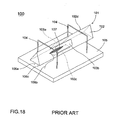
- Fig. 18 is a perspective view of an example of a conventional vibrating gyroscope.
- This vibrating gyroscope 100 comprises a vibrator 101 of a substantially regular triangle bar-shape.
- the vibrator 101 is composed of a vibrating body 102 of a substantially regular triangle bar-shape made up of a permanently elastic metal and piezoelectric elements 103a, 103b, and 103c which are substantially rectangular in shape and which are attached nearly in the center of each of the three side surfaces of the vibrating body 102.
- the piezoelectric element 103c is used for input of a drive signal, and the piezoelectric elements 103a and 103b are used for detection and feedback.
- electrodes (not shown) are formed, and one of them is joined to the vibrating body 102 and the other electrode is connected to one end of the lead wires 106a, 106b, and 106c by soldering, etc.
- the ends of the lead wires 106a, 106b, and 106c which extend to the vicinity of the nodal point of the vibrating body 102 are fixed thereto using elastic adhesive 107, and the other end of the lead wires 106a, 106b, and 106c are led to the surface of the mounting base 105 and connected to a circuit (not shown).
- metallic support members 104 and 104 having the shape of a square letter "C" made up of a thin wire of a high elasticity are joined by, for example, soldering. And the end portions of the support members 104, 104 are joined to one main surface of the mounting base 105 made up of glass epoxy material, etc., and the vibrating body 10 is supported by the mounting base 105 through the support members 104, 104.
- a drive circuit as a feedback loop for self-oscillation of the vibrating body 102 is connected, and because of this drive circuit the vibrator 102 generates bending vibration at a right angle to the surface on which the piezoelectric element 103c is provided.
- This bending vibration is hereinafter referred to as a drive mode (fx mode). While the bending vibration in the drive mode is generated, bending vibration in the direction perpendicular to the drive mode is induced owing to the Coriolis force when the rotation around the axis of the vibrating body 102 is added.
- This bending vibration is called a detection mode (fy mode) in the following explanation.
- the bending vibration in the detection mode causes an output difference between the piezoelectric elements 103a and 103b proportional to the angular velocity, and the angular velocity can be detected by detecting the output difference using a detection circuit.
- the vibrating gyroscope 100 there has arisen the problem that the vibration of the vibrator 101 leaks to the mounting base 105 through the four legs of the support members 104, 104.
- the leakage of the vibration from the four legs of the support members 104, 104 is different. This causes the vibration of the vibrator 101 to become unbalanced in such a way that it becomes difficult to detect an accurate angular velocity.
- the vibrating gyroscope 100 has had a weakness at impact because the support members 104, 104 are formed using a thin wire material.
- the vibrating gyroscope shown in Fig. 18 has a problem that the sensitivity of detecting angular velocity is greatly varied as shown in a graph of Fig. 21 when the frequency characteristic (resonance characteristic) becomes different because of the change of external conditions. That is, as these vibrating gyroscopes are formed so that the resonance frequency in the fx mode coincides with the resonance frequency in the fy mode, they have a good detection sensitivity. However, because the slope of the curve showing the resonance characteristic in the fy mode is sharp, there is a concern that the detection sensitivity may be greatly changed when the resonance frequency in the fy mode corresponding to the resonance frequency in the fx mode is changed owing to the change of external conditions.
- EP 0 682 407 A discloses a vibrating gyroscope including a piezoelectric vibrator.
- the piezoelectric vibrator includes a vibrating body having a regular triangular prism shape. Grooves are formed on one side face of the vibrating body along its width direction. The grooves are formed at portions corresponding to nodal points of the vibrating body. Piezoelectric elements are formed on three side faces of the vibrating body. An M-shaped supporting members are attached to the vibrating body at portions in grooves.
- JP 09-145379 A discloses a support structure for a vibrator.
- Four buffer materials are connected to the sides of the vibrator at the positions corresponding to the nodes of the sides at an interval of 90 degrees in the circumferential direction, and the gaps between the adjacent materials are disposed in Y-axis and X-axis directions.
- the vibrator mounted with the buffer materials is coupled to the support leg.
- the buffer materials follow the bending vibration in the Y-axis of the vibrator and the bending vibration in the X-axis direction of Coriolis force with large twist deformation. The transmission of the bending motions of the respective directions of the vibrator to the leg is effectively stopped.
- the present invention is directed to a vibrating gyroscope that satisfies this need.
- the vibrating gyroscope comprises a bar-shaped vibrator and a support member.
- the bar-shaped vibrator includes a drive element for vibrating the bar-shaped vibrator and a detection element for detecting the vibration of the bar-shaped vibrator and has two grooves therein which extend along a direction perpendicular to a longitudinal direction of the bar-shaped vibrator in the vicinity of two node points of the vibration of the bar-shaped vibrator, respectively.
- the support member has two portions extending within the two grooves, respectively, for supporting the bar-shaped vibrator.
- the support member has a shape in which two arch portions held in a non-horizontal direction are connected by two connecting portions at both ends of the arch portions.
- the arch portions of the support member are connected to the bar-shaped vibrator at respective bottoms of the grooves thereof.
- the arch portions and connecting portions of the support member are integrally formed with each other.
- the arch portions and connecting portions of the support member may have a wire shape.
- the arch portions and connecting portions of the support member have a strip shape.
- the support member may include another connecting portion which is connected between middles of the connecting portions.
- the support member may be formed by bending opposite sides of a flat plate having the square ring shape in the same direction so that the arch portions in the shape of a reversed square bottomed letter "U" are formed.
- the bar-shaped vibrator may have a polygonal cross-section, and each of the grooves is provided in two adjacent side faces of the bar-shaped vibrator.
- the bar-shaped vibrator has a polygonal cross-section, and each of the grooves is provided in one side face of the bar-shaped vibrator.
- Depths of the grooves are preferably adjusted such that resonance frequencies of two directions perpendicular with each other have a predetermined difference.
- the predetermined difference is preferably within the range of about 50 to 150Hz.
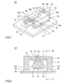
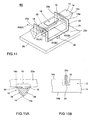
- Fig. 1 is a perspective view of a vibrating gyroscope 10 according to a first embodiment of the present invention.
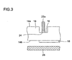
- Fig. 2 is a cross sectional view taken along line II - II of the gyroscope 10 and
- Fig. 3 is a sectional view taken along line III - III.
- the vibrating gyroscope 10 shown in Fig. 1 comprises a vibrator 12.
- the vibrator 12 is composed of a vibrating body 14, a drive piezoelectric element 18, and a detection piezoelectric element 20.
- the vibrating body 14 is formed generally of a material for producing mechanical vibration such as elinvar, iron-nickel alloy, quartz, glass, rock-crystal, ceramics, etc.
- the vibrating body 14 is formed of elinvar and has a regular triangle prism shape.
- Grooves 16, 16 each having a depth in the cross sectional direction of the vibrating body 14 are provided at two points corresponding to the nodal points on an edge line 14a out of three edge lines of the vibrating body 14.
- the grooves 16, 16 have a triangular shape in a direction parallel to the cross sectional direction of the vibrating body 14 (Fig. 2) and a rectangular shape in a direction perpendicular to the cross sectional direction (Fig. 3).
- the grooves 16, 16 are formed so as to have a width at least wider than the thickness of a support member 22 to be described later along the longitudinal direction of the vibrating body 14.
- the cross sectional direction of the vibrating body 14 means the transversal direction at a right angle to the longitudinal direction of the vibrating body 14.
- a drive piezoelectric element 18 is provided for exciting a bending vibration in the fx mode on the vibrating body 14 and a detection piezoelectric element 20 is provided for detecting the deformation of the vibrating body 14.
- the side surface 14b means the bottom surface of the vibrator 12.
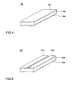
- Fig. 4 is a perspective view showing one example of the drive piezoelectric element 18.
- the drive piezoelectric element 18 includes one piezoelectric plate 18a made up of, for example, piezoelectric ceramics. Electrodes 18b and 18c are formed on opposite surfaces of the piezoelectric plate 18a.
- the drive piezoelectric element 18 is attached on the side surface 14b of the vibrating body 14 so that one end portion of the drive piezoelectric element 18 in its longitudinal direction overlaps with the location corresponding to one of the nodal points in the vibrating body 14 as shown in Fig. 6. At this time the electrode 18b of the drive piezoelectric element 18 is joined to the vibrating body 14 so as to make electrical contact with the vibrating body 14.
- Fig. 5 is a perspective view showing one example of the detection piezoelectric element 20.
- the detection piezoelectric element 20 includes one piezoelectric plate 20a made up of, for example, piezoelectric ceramics.
- an electrode 20b is formed over the entire surface on one surface of the surfaces opposite to each other in the thickness direction of the piezoelectric plate 20a.
- Divided electrodes 20c and 20d are arranged on another surface of the piezoelectric plate 20a so as to be spaced in a direction perpendicular to the longitudinal direction of the piezoelectric plate 20.
- the detection piezoelectric element 20 is attached on the side surface 14b of the vibrating body 14 so that one end portion of the detection piezoelectric element 20 in its longitudinal direction overlaps with the location corresponding to the other nodal point in the vibrating body 14 as shown in Fig. 6. Then, an electrode 20b of the detection piezoelectric element 20 is joined to the vibrating body 14 so as to make electrical contact with the vibrating body 14.
- the vibrating gyroscope 10 comprises a support member 22 to support the vibrator 12 so that it is suspended.
- the support member 22 is made of a metal such as elinvar and has a shape in which two arch portions 22a, 22a are held in a non-horizontal direction, preferably in a substantial vertical direction, and are connected by two connecting portions 22b, 22b at both ends of the arch portions 22a, 22a such that the arch portions 22a, 22a and connecting portions 22b, 22b create a cubic space therebetween.
- the arch portions 22a, 22a may be rectangular, triangular, oblong, circular, or the like.
- the arch portions 22a, 22a and the connecting portions 22b, 22b are formed integrally into the support member 22.
- the arch portions 22a and connecting portions 22b may have a wire shape or a strip shape, but it is more preferable to employ the strip-shaped arch portions 22a and the strip-shaped connecting portions 22b in view of mechanical strength.
- the support member 22 may be formed by bending opposite sides of a flat plate having the square ring shape in the same direction so that the arch portions 22a, 22a in the shape of a reversed square bottomed letter "U" are formed.
- Protrusions 24, 24, for example, of a nearly rectangular shape are integrally formed respectively in the middle of the arch portions 22a, 22a of the support member 22.
- Both of the arch portions 22a, 22a of the support member 22 are inserted into the grooves 16, 16 of the vibrator 12, respectively, with the tip portions of the protrusions 24, 24 in contact with the bottom of the grooves 16, 16 and joined thereto, for example, by welding.
- the other portions of the sides 22a, 22a do not contact the inside surface of the grooves 16, 16. In this way the support member 22 are joined to the vicinity of the nodal points of the vibrator 12 and electrically connected to the vibrator 12.
- the vibrating gyroscope 10 further comprises a plate-like mounting base 26 made up of metal, etc.
- a mounting base 26 made up of metal, etc.
- two mounting block 28, 28 are attached by means of welding, etc.
- the middle point of the connecting portions 22b of the support member 22 is joined onto the mounting blocks 28, 28, respectively.
- the vibrator 12 is supported on the mounting base 26 through the mounting blocks 28 so as to be suspended by the support member 22.
- I-V conversion circuits 30, 30 are connected to the divided electrodes 20c and 20d of the detection piezoelectric element 20 in the vibrating gyroscope 10, respectively.
- the output from the two I-V conversion circuits 30, 30 is summed, and the resultant signal is input to an auto gain control (AGC) circuit 32.
- AGC auto gain control
- phase correction circuit 34 and a synchronous detection circuit 38 are connected on the output side of the AGC circuit 32.
- the output side of the phase correction circuit 34 is connected to the electrode 18c of the drive piezoelectric element 18.
- the bending vibration in the fx mode means bending vibration in the direction perpendicular to the side surface 14b on which the drive piezoelectric element 18 is formed.
- the deformation of the vibrating body 14 because of this bending vibration is detected, and is output as a detected signal from the split electrodes 20c, 20c respectively.
- the resultant of the detected signals output is fedback to the drive piezoelectric element 18 as a driving piece through the AGC circuit 32 and phase correction circuit 34.
- the vibrator 12 in the vibrating gyroscope 10 generates mechanically stable self-excited vibration.
- the output of the I-V conversion circuits 30, 30 is input to the differential amplifier 36 respectively.
- the output from the differential amplifier 36 is input to the synchronous detection circuit, and synchronous detection is performed based on the signal from the AGC circuit 32.
- the output signal of the synchronous detection circuit 38 is input as an output signal from the vibrating gyroscope 10 through a smoothing circuit 40 and a DC amplifier 42.
- bending vibration in the fy mode is induced in the vibrating body 14 owing to the Coriolis force when an angular velocity is applied and the vibrator 12 rotates around its axis.
- the bending vibration in the fy mode means vibration in the direction perpendicular to the direction of the vibration in the fx mode as shown in Fig. 7B.
- a voltage difference is generated between the divided electrode 20c and the divided electrode 2Od of the detection piezoelectric element 20, and this voltage difference is output from the differential amplifier 36.
- the output signal from the differential amplifier 36 is caused by the change of direction of the vibration of the vibrator 12, the output signal is the detection signal corresponding to the rotating angular velocity applied to the vibrating gyroscope 10. Therefore, after synchronous detection of the output signal from differential amplifier 36 has been performed in the synchronous detection circuit 38, through smoothing in the smoothing circuit 40 and amplification by the DC amplifier 42, a detection signal in accordance with the angular velocity applied to the vibrating gyroscope 10 can be obtained.
- Fig. 7A is a diagrammatic side view showing one specific embodiment of a vibrating body 14 to be used in the vibrating gyroscope 10 shown in Fig. 1, and Fig. 7B is its diagrammatic front view.
- the vibrating body 14 used here is a triangular prism with a total length of 35 mm and a height of 2 mm made up of elinvar.
- the depth of the grooves 16 means the length from the edge line 14a to the bottom of the grooves 16, and the width of the grooves 16 means the length in the longitudinal direction of the vibrating body 14.
- the difference f between the resonance frequency in the fx mode and the resonance frequency in the fy mode (hereinafter, simply referred to as the difference of resonance frequency) is shown as a graph in Fig. 8.
- the graph in Fig. 9 shows the difference of resonance frequency f when the depth and width of the grooves 16 were set as 1.0 mm and 0.7 mm to 1.3 mm respectively in the vibrating body 14 shown in Fig. 7.
- Fig. 10 is a graph showing the relation among the difference of resonance frequency ⁇ f, the temperature (°C), and the changing rate of sensitivity (%) in the vibrating gyroscope 10 using the vibrating body 14 shown in Fig. 7.
- the changing rate of sensitivity means the relative sensitivity referenced to the sensitivity at a temperature of 25°C.
- the temperature means a temperature in the external environment.
- the difference of resonance frequency ⁇ f is within the range of about 50 to 150Hz.
- Fig. 11 shows the relationship between the shift due to the change of external conditions of the resonance frequency characteristic in the fy mode and the sensitivity for detecting angular velocity in the vibrating gyroscope 10 relating to the present invention.
- This vibrating gyroscope 10 is formed so that by adjustment of the shape of the groove 16 it is formed in advance so as to make the difference of resonance frequency f large and the resonance frequency in the fx mode corresponding to the frequency around which the characteristic curve of the resonance frequency in the fy mode has a bottom area of a slow slope. Therefore, even if the resonance frequency in the fx mode shifts due to the change of external conditions, the change of the detection sensitivity is made small.
- the vibrating gyroscope 10 shown in Fig. 1 is hardly affected by external impact, etc. because the support member 22 has the shape in which the arch portions are connected by two connecting portions. Especially, when the support member 22 is formed of a flat rectangular ring plate. Furthermore, as the grooves 16 are formed in the vicinity of the nodal points of the vibrator 12 and the vibrator 12 is supported by joining the tip of the protrusions 24 of the support member 22 to part of the bottom of the grooves 16, it is possible to support the vibrator 12 at the portion nearer to the nodal points. For that reason, the rigidity of the support member 22 makes it hard for the vibration of the vibrator 12 to be damped down and accordingly the leak of the vibration is made small.
- the grooves 16 are formed in the shape of a slit which has a depth from the edge line 14a of the vibrator 12 toward the side surface 14b, the difference of resonance frequency f between the fx mode and the fy mode can be adjusted at a desired value by controlling the width and depth of the groove 16. Once the difference of resonance frequency ⁇ f has been adjusted in advance to become large, the fluctuation of detecting sensitivity due to the change of external conditions can be decreased.
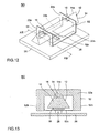
- Fig. 12 is a perspective view of a modified example of the vibrating gyroscope shown in Fig. 1, and Fig. 13 is a sectional view taken on line XIII - XIII of Fig. 12. Note that the elements which are the same as those in the gyroscope 10 shown in Fig. 1 are denoted by the same reference numerals.
- the vibrating gyroscope 50 shown in Fig. 12 is different in the construction of support from the vibrating gyroscope 10 in Fig. 1.
- This vibrating gyroscope 50 comprises a support member 52 to support the vibrator 12 so that it is suspended.
- the support member 52 is different form the support member 22 shown in Fig. 1 in that the support member 52 further includes a connecting portion 52c which connects between the center portions of the two connecting portions 22b.
- the support member 52 is fixed to the mounting block 28 and the mounting block 28 is fixed on the mounting base 26.
- the vibrator 12 is supported on the mounting base 26 through the mounting portion 28 so as to be hanged down by the support member 52.
- the vibrating gyroscope 50 shown in Fig. 12 is also hardly affected by external impact, etc. and is able to give the same effects as the vibrating gyroscope 10 shown in Fig. 1.
- Fig. 14 is a perspective view showing another embodiment of the vibrating gyroscope relating to the present invention.
- Fig. 15A is a sectional view taken on line XV(A) XV(A) of Fig. 14, and
- Fig. 15B is a sectional view taken on line XV(B)-XV(B) of Fig. 14.
- the vibrating gyroscope 60 shown in Fig. 14 is different in formation of the groove 16 and support of the vibrator 12 from the vibrating gyroscope 10. That is, in the vibrating gyroscope 60, the groove 16 extending in the direction perpendicular to the longitudinal direction of the vibrating body 14 is formed in the side surface 14b of the vibrating body 14 and in the vicinity of two nodal points in the vibrating body 14.
- the edge line 14a of the vibrator 12 is arranged on the side of the mounting base 26, and the side surface 14b is on the opposite side to the mounting base 26. Therefore, in the vibrating gyroscope 60, the side surface 14b is located as an upper side, and the vibrator 12 is supported with a front view of an upside-down triangle shape so as to be suspended over the mounting base 26.
- a drive piezoelectric element 18 is attached nearly in the middle of the side surface 14b of the vibrating body 14.
- Piezoelectric elements 18 of the same construction as the drive piezoelectric element 18 is attached as a detection piezoelectric element nearly in the middle of the two adjacent side surfaces with the edge line 14a of the vibrating body 14 therebetween.
- the two piezoelectric elements 18 as a detection piezoelectric element are connected to the IV conversion circuits 30, 30 in place of the divided electrodes 20c and 20d of the detection piezoelectric element 20 in the circuit diagram shown in Fig. 6.
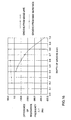
- Fig. 16 is a graph showing the relation of the difference of resonance frequency ⁇ f (Hz) to the location of the groove to be formed and the depth (mm) of the groove.
- ⁇ f the difference of resonance frequency
- Fig. 16 when the groove 16 is formed from the side surface 14b, the relation between the depth of the groove and the difference of resonance frequency ⁇ f is shown by a broken line, and when the groove 16 is formed from the edge line 14a, the relation between the depth of the groove and the difference of resonance frequency ⁇ f is shown by a solid line.
- the above figure is different in numerical value from Fig. 9, as the vibrating body used to obtain the result of evaluation in Fig. 9 is different in shape from the vibrating body used to obtain the result of evaluation shown in Fig. 16.
- the vibrating gyroscope 60 shown in Fig. 14 is hardly affected by external impact, etc. because of the same reasons mentioned above. Also, in the vibrating gyroscope 60, as the difference of resonance frequency ⁇ f between in the fx mode and in the fy mode varies little, the detecting sensitivity of angular velocity becomes high.
- Fig. 17 is a perspective view of a modified example of the vibrating gyroscope shown in Fig. 14.
- the vibrating gyroscope 70 shown in Fig. 17 is different in only construction of the support from the vibrating gyroscope 60 in Fig. 14.
- the support member 52 shown in Fig. 12 is employed in the vibrating gyroscope 70 shown in Fig. 17 .
- the support member 52 is fixed on the mounting base 26 through the mounting block 28.
- the vibrating body 14 may be formed in a square prism shape or other polygonal prism shapes, and also may be formed into a columnar shape.
- the difference of resonance frequency ⁇ f between the fx mode and the fy mode can be freely adjusted by controlling the width and depth of the groove, and once the difference of resonance frequency ⁇ f has been adjusted in advance, the alteration of the detection sensitivity owing to the change of external conditions may be reduced.
Landscapes
- Engineering & Computer Science (AREA)
- Manufacturing & Machinery (AREA)
- Physics & Mathematics (AREA)
- General Physics & Mathematics (AREA)
- Radar, Positioning & Navigation (AREA)
- Remote Sensing (AREA)
- Gyroscopes (AREA)
Claims (11)
- Gyroscope à vibration, comprenant :un vibrateur en forme de barre (12) comprenant un élément d'entraînement (18) destiné à faire vibrer le vibrateur en forme de barre (12) et un élément de détection (20) destiné à détecter la vibration du vibrateur en forme de barre (12), le vibrateur en forme de barre (12) possédant deux rainures (16) qui s'étendent le long d'une direction perpendiculaire à une direction longitudinale du vibrateur en forme de barre (12) à une position correspondant aux deux points de noeud de la vibration du vibrateur en forme de barre (12), respectivement ; etun élément de support (22 ; 52) ayant une forme avec deux parties arquées (22a) reliées au vibrateur en forme de barre (12) au niveau de parties inférieures respectives des rainures de celui-ci ;caractérisé en ce queles deux parties arquées (22a) de l'élément de support (22, 52) sont reliées par deux parties de liaison (22b) aux deux extrémités des parties arquées (22a),le gyroscope à vibration comprend en outre un élément de monture (28) supportant l'élément de support (22 ; 52) sensiblement à une position centrale entre les deux parties arquées (22a).
- Gyroscope à vibration selon la revendication 1, dans lequel l'élément de monture possède deux blocs de monture (28), dans lequel sensiblement le point central de chacune des deux parties de liaison (22b) de l'élément de support (22) est joint à un bloc de monture (28), respectivement.
- Gyroscope à vibration selon l'une quelconque des revendications 1 et 2, dans lequel l'élément de support (52) comprend une partie de liaison supplémentaire (52c) qui est reliée entre les centres des parties de liaison (22b), et dans lequel l'élément de monture possède un seul bloc de monture (28) fixé à la partie de liaison supplémentaire (52c).
- Gyroscope à vibration selon l'une quelconque des revendications 1 à 3, dans lequel les parties arquées (22a) et les parties de liaison (22b) de l'élément de support (22) sont formées de manière intégrée les unes avec les autres.
- Gyroscope à vibration selon la revendication 4, dans lequel les parties arquées (22a) et les parties de liaison (22b) de l'élément de support (22) ont des formes de fil.
- Gyroscope à vibration selon la revendication 4, dans lequel les parties arquées (22a) et les parties de liaison (22b) de l'élément de support ont des formes de bande.
- Gyroscope à vibration selon l'une quelconque des revendications 1 à 6, dans lequel l'élément de support (22) est formé en pliant les côtés opposés d'une plaque plate ayant la forme d'une bague carrée dans la même direction de sorte que les parties arquées (22a) ayant la forme d'une lettre « U » à fond carré inversé soient formées.
- Gyroscope à vibration selon l'une quelconque des revendications 1 à 7, dans lequel le vibrateur en forme de barre (12) présente une coupe transversale polygonale, et chacune des rainures (16) est disposée dans deux faces latérales adjacentes du vibrateur en forme de barre (12).
- Gyroscope à vibration selon l'une quelconque des revendications 1 à 8, dans lequel le vibrateur en forme de barre (12) présente une coupe transversale polygonale, et chacune des rainures (16) est disposée dans une seule face latérale du vibrateur en forme de barre (12).
- Gyroscope à vibration selon l'une quelconque des revendications 1 à 9, dans lequel les profondeurs des rainures (16) sont ajustées de sorte que les fréquences de résonance de deux directions perpendiculaires l'une à l'autre aient une différence prédéterminée.
- Gyroscope à vibration selon la revendication 10, dans lequel la différence prédéterminée se trouve dans la plage d'environ 50 à 150 Hz.
Applications Claiming Priority (3)
| Application Number | Priority Date | Filing Date | Title |
|---|---|---|---|
| JP9268058A JPH1194557A (ja) | 1997-09-12 | 1997-09-12 | 振動ジャイロ |
| JP268058/97 | 1997-09-12 | ||
| JP26805897 | 1997-09-12 |
Publications (3)
| Publication Number | Publication Date |
|---|---|
| EP0902253A2 EP0902253A2 (fr) | 1999-03-17 |
| EP0902253A3 EP0902253A3 (fr) | 2000-08-30 |
| EP0902253B1 true EP0902253B1 (fr) | 2007-04-11 |
Family
ID=17453312
Family Applications (1)
| Application Number | Title | Priority Date | Filing Date |
|---|---|---|---|
| EP98116820A Expired - Lifetime EP0902253B1 (fr) | 1997-09-12 | 1998-09-04 | Gyroscope à vibration |
Country Status (5)
| Country | Link |
|---|---|
| US (1) | US6035713A (fr) |
| EP (1) | EP0902253B1 (fr) |
| JP (1) | JPH1194557A (fr) |
| CN (1) | CN1091515C (fr) |
| DE (1) | DE69837512D1 (fr) |
Families Citing this family (14)
| Publication number | Priority date | Publication date | Assignee | Title |
|---|---|---|---|---|
| JP3649090B2 (ja) * | 2000-06-16 | 2005-05-18 | 株式会社村田製作所 | 振動ジャイロ用振動子及びそれを用いた振動ジャイロ及びそれを用いた電子装置 |
| JP3687609B2 (ja) * | 2001-04-19 | 2005-08-24 | 株式会社村田製作所 | 振動ジャイロおよびそれを用いた電子装置 |
| CN100538687C (zh) | 2002-09-03 | 2009-09-09 | 美商内数位科技公司 | 两不同终端间协议地址交换的方法及装置 |
| DE10317158B4 (de) * | 2003-04-14 | 2007-05-10 | Litef Gmbh | Verfahren zur Ermittlung eines Nullpunktfehlers in einem Corioliskreisel |
| DE10317159B4 (de) * | 2003-04-14 | 2007-10-11 | Litef Gmbh | Verfahren zur Kompensation eines Nullpunktfehlers in einem Corioliskreisel |
| US7322238B2 (en) * | 2004-03-03 | 2008-01-29 | Northrop Grumman Corporation | Support of vibrating beam near nodal point |
| CA2498178A1 (fr) * | 2004-03-03 | 2005-09-03 | Northrop Grumman Corporation | Support de poutre vibrante pres du point nodal |
| JP5145637B2 (ja) * | 2005-03-04 | 2013-02-20 | ソニー株式会社 | 振動型ジャイロセンサ |
| US20090212475A1 (en) * | 2005-07-03 | 2009-08-27 | Hermann Tropf | Fastening Means Preventing The Transmission of Shocks and Vibrations |
| US7392702B2 (en) * | 2005-08-08 | 2008-07-01 | Litton Systems Inc. | Method for modifying the location of nodal points of a vibrating beam |
| JP3969459B1 (ja) * | 2006-04-26 | 2007-09-05 | 株式会社村田製作所 | 振動ジャイロ |
| CN102278983B (zh) * | 2011-07-22 | 2014-03-26 | 上海交通大学 | 具有三角形振子的硅微陀螺仪及其制作方法 |
| US8991247B2 (en) * | 2011-10-21 | 2015-03-31 | The Regents Of The University Of California | High range digital angular rate sensor based on frequency modulation |
| FI125238B (en) | 2012-06-29 | 2015-07-31 | Murata Manufacturing Co | Improved vibration gyroscope |
Family Cites Families (5)
| Publication number | Priority date | Publication date | Assignee | Title |
|---|---|---|---|---|
| DE69310799T2 (de) * | 1992-03-30 | 1997-11-13 | Murata Manufacturing Co | Vibrator mit abgeglichenen Kantenbereichen |
| JPH07128063A (ja) * | 1993-11-04 | 1995-05-19 | Murata Mfg Co Ltd | 振動ジャイロ |
| JP3211562B2 (ja) * | 1994-05-12 | 2001-09-25 | 株式会社村田製作所 | 圧電振動子 |
| JPH0843106A (ja) * | 1994-07-27 | 1996-02-16 | Murata Mfg Co Ltd | 振動ジャイロ |
| JPH09145379A (ja) * | 1995-11-22 | 1997-06-06 | Akai Electric Co Ltd | 振動子の支持構造 |
-
1997
- 1997-09-12 JP JP9268058A patent/JPH1194557A/ja active Pending
-
1998
- 1998-09-03 US US09/146,885 patent/US6035713A/en not_active Expired - Fee Related
- 1998-09-04 EP EP98116820A patent/EP0902253B1/fr not_active Expired - Lifetime
- 1998-09-04 DE DE69837512T patent/DE69837512D1/de not_active Expired - Lifetime
- 1998-09-11 CN CN98119169A patent/CN1091515C/zh not_active Expired - Fee Related
Also Published As
| Publication number | Publication date |
|---|---|
| EP0902253A2 (fr) | 1999-03-17 |
| DE69837512D1 (de) | 2007-05-24 |
| US6035713A (en) | 2000-03-14 |
| JPH1194557A (ja) | 1999-04-09 |
| EP0902253A3 (fr) | 2000-08-30 |
| CN1091515C (zh) | 2002-09-25 |
| CN1211725A (zh) | 1999-03-24 |
Similar Documents
| Publication | Publication Date | Title |
|---|---|---|
| EP0649002B1 (fr) | Gyroscope de vibration | |
| EP0902253B1 (fr) | Gyroscope à vibration | |
| US6378369B1 (en) | Angular velocity sensor | |
| US6023973A (en) | Vibrating gyroscope and adjusting method therefor | |
| EP0597338B1 (fr) | Gyromètre vibrant | |
| EP0682407B1 (fr) | Vibrateur piézoélectrique | |
| EP0744593B1 (fr) | Gyroscope à vibration | |
| KR100361118B1 (ko) | 2축 각속도 검출용 진동자 및 이를 구비한 진동 자이로스코프 | |
| JPH0650761A (ja) | 振動ジャイロ | |
| EP0585785B1 (fr) | Gyromètre vibrant | |
| JP2996157B2 (ja) | 振動ジャイロ | |
| JP3045053B2 (ja) | 振動ジャイロ | |
| EP0684450B1 (fr) | Structure de support d'un vibreur | |
| EP0563762B1 (fr) | Gyroscope vibrateur dont les éléments piézoélectriques se trouvent près noeuds vibratoires | |
| JPH0650762A (ja) | 振動ジャイロ | |
| JPH02228518A (ja) | 振動子の支持構造 | |
| JPH0251066A (ja) | 振動ジャイロ | |
| JPH07103769A (ja) | 振動ジャイロ | |
| JP2000258164A (ja) | 振動ジャイロ | |
| JP2000002541A (ja) | 振動ジャイロ | |
| JPH1194558A (ja) | 振動ジャイロ | |
| JPH07122968A (ja) | 振動子の支持構造 | |
| JPH06174474A (ja) | 振動子の支持構造 | |
| JPH08159775A (ja) | 振動ジャイロ | |
| JPH07139951A (ja) | 角速度センサ |
Legal Events
| Date | Code | Title | Description |
|---|---|---|---|
| PUAI | Public reference made under article 153(3) epc to a published international application that has entered the european phase |
Free format text: ORIGINAL CODE: 0009012 |
|
| 17P | Request for examination filed |
Effective date: 19980904 |
|
| AK | Designated contracting states |
Kind code of ref document: A2 Designated state(s): DE FR GB SE |
|
| AX | Request for extension of the european patent |
Free format text: AL;LT;LV;MK;RO;SI |
|
| PUAL | Search report despatched |
Free format text: ORIGINAL CODE: 0009013 |
|
| AK | Designated contracting states |
Kind code of ref document: A3 Designated state(s): AT BE CH CY DE DK ES FI FR GB GR IE IT LI LU MC NL PT SE |
|
| AX | Request for extension of the european patent |
Free format text: AL;LT;LV;MK;RO;SI |
|
| AKX | Designation fees paid |
Free format text: DE FR GB SE |
|
| 17Q | First examination report despatched |
Effective date: 20050620 |
|
| GRAP | Despatch of communication of intention to grant a patent |
Free format text: ORIGINAL CODE: EPIDOSNIGR1 |
|
| GRAS | Grant fee paid |
Free format text: ORIGINAL CODE: EPIDOSNIGR3 |
|
| GRAA | (expected) grant |
Free format text: ORIGINAL CODE: 0009210 |
|
| AK | Designated contracting states |
Kind code of ref document: B1 Designated state(s): DE FR GB SE |
|
| REG | Reference to a national code |
Ref country code: GB Ref legal event code: FG4D |
|
| REF | Corresponds to: |
Ref document number: 69837512 Country of ref document: DE Date of ref document: 20070524 Kind code of ref document: P |
|
| PG25 | Lapsed in a contracting state [announced via postgrant information from national office to epo] |
Ref country code: SE Free format text: LAPSE BECAUSE OF FAILURE TO SUBMIT A TRANSLATION OF THE DESCRIPTION OR TO PAY THE FEE WITHIN THE PRESCRIBED TIME-LIMIT Effective date: 20070711 |
|
| RAP2 | Party data changed (patent owner data changed or rights of a patent transferred) |
Owner name: MURATA MANUFACTURING CO., LTD. |
|
| EN | Fr: translation not filed | ||
| PGFP | Annual fee paid to national office [announced via postgrant information from national office to epo] |
Ref country code: GB Payment date: 20070824 Year of fee payment: 10 |
|
| PLBE | No opposition filed within time limit |
Free format text: ORIGINAL CODE: 0009261 |
|
| STAA | Information on the status of an ep patent application or granted ep patent |
Free format text: STATUS: NO OPPOSITION FILED WITHIN TIME LIMIT |
|
| 26N | No opposition filed |
Effective date: 20080114 |
|
| PG25 | Lapsed in a contracting state [announced via postgrant information from national office to epo] |
Ref country code: FR Free format text: LAPSE BECAUSE OF FAILURE TO SUBMIT A TRANSLATION OF THE DESCRIPTION OR TO PAY THE FEE WITHIN THE PRESCRIBED TIME-LIMIT Effective date: 20071207 Ref country code: DE Free format text: LAPSE BECAUSE OF FAILURE TO SUBMIT A TRANSLATION OF THE DESCRIPTION OR TO PAY THE FEE WITHIN THE PRESCRIBED TIME-LIMIT Effective date: 20070712 |
|
| PG25 | Lapsed in a contracting state [announced via postgrant information from national office to epo] |
Ref country code: FR Free format text: LAPSE BECAUSE OF FAILURE TO SUBMIT A TRANSLATION OF THE DESCRIPTION OR TO PAY THE FEE WITHIN THE PRESCRIBED TIME-LIMIT Effective date: 20070411 |
|
| GBPC | Gb: european patent ceased through non-payment of renewal fee |
Effective date: 20080904 |
|
| PG25 | Lapsed in a contracting state [announced via postgrant information from national office to epo] |
Ref country code: GB Free format text: LAPSE BECAUSE OF NON-PAYMENT OF DUE FEES Effective date: 20080904 |