EP0903745A2 - Batterieeinlegemechanismus - Google Patents
Batterieeinlegemechanismus Download PDFInfo
- Publication number
- EP0903745A2 EP0903745A2 EP98203900A EP98203900A EP0903745A2 EP 0903745 A2 EP0903745 A2 EP 0903745A2 EP 98203900 A EP98203900 A EP 98203900A EP 98203900 A EP98203900 A EP 98203900A EP 0903745 A2 EP0903745 A2 EP 0903745A2
- Authority
- EP
- European Patent Office
- Prior art keywords
- battery
- lid
- mechanical chassis
- cassette
- lid portion
- Prior art date
- Legal status (The legal status is an assumption and is not a legal conclusion. Google has not performed a legal analysis and makes no representation as to the accuracy of the status listed.)
- Granted
Links
Images


Classifications
-
- G—PHYSICS
- G11—INFORMATION STORAGE
- G11B—INFORMATION STORAGE BASED ON RELATIVE MOVEMENT BETWEEN RECORD CARRIER AND TRANSDUCER
- G11B33/00—Constructional parts, details or accessories not provided for in the other groups of this subclass
- G11B33/02—Cabinets; Cases; Stands; Disposition of apparatus therein or thereon
-
- G—PHYSICS
- G11—INFORMATION STORAGE
- G11B—INFORMATION STORAGE BASED ON RELATIVE MOVEMENT BETWEEN RECORD CARRIER AND TRANSDUCER
- G11B33/00—Constructional parts, details or accessories not provided for in the other groups of this subclass
- G11B33/12—Disposition of constructional parts in the apparatus, e.g. of power supply, of modules
- G11B33/121—Disposition of constructional parts in the apparatus, e.g. of power supply, of modules the apparatus comprising a single recording/reproducing device
-
- G—PHYSICS
- G11—INFORMATION STORAGE
- G11B—INFORMATION STORAGE BASED ON RELATIVE MOVEMENT BETWEEN RECORD CARRIER AND TRANSDUCER
- G11B15/00—Driving, starting or stopping record carriers of filamentary or web form; Driving both such record carriers and heads; Guiding such record carriers or containers therefor; Control thereof; Control of operating function
- G11B15/675—Guiding containers, e.g. loading, ejecting cassettes
- G11B15/67581—Guiding containers, e.g. loading, ejecting cassettes with pivoting movement of the cassette holder
-
- G—PHYSICS
- G11—INFORMATION STORAGE
- G11B—INFORMATION STORAGE BASED ON RELATIVE MOVEMENT BETWEEN RECORD CARRIER AND TRANSDUCER
- G11B31/00—Arrangements for the associated working of recording or reproducing apparatus with related apparatus
- G11B31/006—Arrangements for the associated working of recording or reproducing apparatus with related apparatus with video camera or receiver
-
- G—PHYSICS
- G11—INFORMATION STORAGE
- G11B—INFORMATION STORAGE BASED ON RELATIVE MOVEMENT BETWEEN RECORD CARRIER AND TRANSDUCER
- G11B33/00—Constructional parts, details or accessories not provided for in the other groups of this subclass
- G11B33/02—Cabinets; Cases; Stands; Disposition of apparatus therein or thereon
- G11B33/08—Insulation or absorption of undesired vibrations or sounds
-
- H—ELECTRICITY
- H04—ELECTRIC COMMUNICATION TECHNIQUE
- H04N—PICTORIAL COMMUNICATION, e.g. TELEVISION
- H04N23/00—Cameras or camera modules comprising electronic image sensors; Control thereof
- H04N23/50—Constructional details
- H04N23/51—Housings
Definitions
- the single-unit video camera-recorder has various mechanical restrictions, such as where to dispose a cassette eject button and how to provide a cassette eject button locking mechanism.
- the battery accommodating mechanism portion has, however, encountered the problems that it is difficult to load the rechargeable battery into the battery accommodating portion and that the loading of the rechargeable battery is hard to understand. Further, since the locking mechanism for positioning the battery in the battery accommodating portion is complicated in structure, the number of assembly parts is unavoidably increased. There is then the problem that the assembling of the battery mechanism portion is troublesome for the user. Furthermore, since the battery mechanism portion is disposed on the electronic equipment at a very restricted place, the battery mechanism portion tends to be restricted from a plan or design standpoint. Therefore, it is unavoidable that the electronic equipment is deteriorated in outer face.
- a recent trend of a recording apparatus is that the recording apparatus is more and more miniaturized and reduced in weight.
- a mechanical chassis on which important mechanism portions of the recording apparatus are mounted or a cabinet forming an outer housing of the recording apparatus is reduced in thickness in order to reduce the weight thereof.
- the mechanical chassis or the cabinet can be reduced in weight when it is reduced in thickness, a rigidity (strength) thereof is lowered unavoidably. For this reason, the mechanical chassis or cabinet tends to be deformed by an external stress, such as a twisting force or the like.
- An important problem caused when the mechanical chassis or cabinet is deformed by the twisting force or the like is that an accurate tape path cannot be formed on a drum by a very small displacement produced between tape path mechanisms provided on the mechanical chassis.
- a rechargeable battery can be loaded with ease onto electronic equipment
- the battery loading mechanism can be easy to handle and a locking mechanism of a battery loading mechanism can be simplified in structure and the number of assembly parts can be reduced considerably.
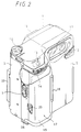
- a lens window 11 of a camera portion is provided on the upper portion of the front wall of the main body portion 2.
- a sound collecting portion 12 is provided near the lens window 11.
- the main body portion 2 includes a camera mode start/stop button 13 provided on the upper one side thereof.
- a switching lever 14 is provided near the start/stop button 14 to switch a wide angle mode and a telephoto mode of the camera portion.
- a camera mode and video mode switching operation dial 15 is provided on the upper portion of another one side of the main body portion 2.
- a viewfinder 16 is provided on the upper rear surface portion of the main body portion 2.
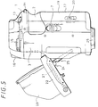
- the lid portion 3 includes on its rear wall a liquid crystal display portion 21 which can display a picture to be monitored as shown in FIG. 1.
- the liquid crystal display portion 21 is held by a frame 22 and the frame 22 includes an openable and closable hood 23 of a foldable type. The user can watch the liquid crystal display portion 21 by spreading the hood 23 as shown in FIG. 5.
- the frame 22 is pivotally supported at its upper end portion to the lid portion 3 by means of a hinge metal fitting 24.
- An angle of the frame 22 can be changed by an ancillary arm 25 as shown in FIG. 5. Therefore, the cameraman can take a picture while watching the liquid crystal display portion 21 under the condition that the liquid crystal display portion 21 is set at a desired angle by rotating the frame 22 in adjustment.
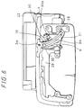
- the lid portion 3 can be released from the locked state when the lock member 31 of the guide arm 9 passes the spring member 32 by a force in the closing direction. Simultaneously, the operation member 28 of the guide arm 9 is released from the projected member 30a of the eject switch 30 and the eject switch 30 is disabled so that the cassette compartment 27 is moved at the loading position in a ganged relation to the eject switch 30. Thereafter, the levers 5, 5 provided on the open end portion of the lid portion 3 are locked into the engagement holes 6, 6 bored through the main body portion 2 side, thereby the lid portion 3 being placed in the closed state.
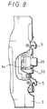
- the pop-up member 35 is urged against the end portion of the main body portion 2 against the spring force of the spring member 34.
- the lid portion 3 is released from the locked state by operating the lid lock releasing slide switch 7, the lid portion 3 can be popped up under the spring force of the spring member 34 urged against the pop-up member 35.
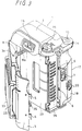
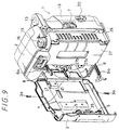
- the lid portion 3 can be rotated about the hinge portion 4 in the opening direction by removing the screws 3a, 3a which secured the guide frames 8, 9 to the lid portion 3, as shown in FIG. 9. Therefore, it is possible to repair and inspect the drum head 27a, such as cleaning of the drum head 27a or exchange the worn drum head 27a or to repair and inspect the tape path mechanism portion, such as cleaning of the tape guide system 27a of the tape path mechanism portion and a tape path adjustment with the ease without disassembling the main body portion 2 and the lid portion 3.
- the lid portion 3 Since the lid portion 3 is locked under the condition that it is opened at maximum, the lid portion 3 can be prevented from being closed so long as the lid portion 3 is not closed by a recklessly large force. Therefore, the tape cassette can reliably be loaded to and/or unloaded from the cassette compartment which is placed under the eject state.
- the lid portion 2 is set in the popped-up state so long as the lid portion 3 is not closed completely. Therefore, it is possible to prevent the recording or reproducing apparatus from being used under the condition that the lid portion 3 remains opened.
- the lid portion includes a pair of guide arms which assist the lid portion to be opened and closed relative to the main body portion in which a cassette eject switch is opened in a ganged relation with the opening operation of the lid portion, the cassette eject button need not be disposed on the surface of the housing of the recording or reproducing apparatus. As a consequence, it becomes possible to reliably prevent the tape cassette from being ejected during the single-unit video camera recorder is being operated.
Landscapes
- Engineering & Computer Science (AREA)
- Multimedia (AREA)
- Signal Processing (AREA)
- Studio Devices (AREA)
- Casings For Electric Apparatus (AREA)
- Battery Mounting, Suspending (AREA)
Applications Claiming Priority (10)
| Application Number | Priority Date | Filing Date | Title |
|---|---|---|---|
| JP209625/93 | 1993-08-24 | ||
| JP20962693A JP3318630B2 (ja) | 1993-08-24 | 1993-08-24 | 録画装置におけるメカシャーシの保持機構 |
| JP20962693 | 1993-08-24 | ||
| JP5209625A JPH0767007A (ja) | 1993-08-24 | 1993-08-24 | 電子機器装置のバッテリ装着機構 |
| JP20962493A JP3240767B2 (ja) | 1993-08-24 | 1993-08-24 | 記録及び/又は再生装置のカセット着脱機構及び記録及び/又は再生装置 |
| JP209624/93 | 1993-08-24 | ||
| JP209626/93 | 1993-08-24 | ||
| JP20962493 | 1993-08-24 | ||
| JP20962593 | 1993-08-24 | ||
| EP94306101A EP0640973B1 (de) | 1993-08-24 | 1994-08-18 | Kassetten-Auswurfmechanismus, Batterielademechanismus, und mechanische Gestellträgervorrichtung |
Related Parent Applications (1)
| Application Number | Title | Priority Date | Filing Date |
|---|---|---|---|
| EP94306101A Division EP0640973B1 (de) | 1993-08-24 | 1994-08-18 | Kassetten-Auswurfmechanismus, Batterielademechanismus, und mechanische Gestellträgervorrichtung |
Publications (3)
| Publication Number | Publication Date |
|---|---|
| EP0903745A2 true EP0903745A2 (de) | 1999-03-24 |
| EP0903745A3 EP0903745A3 (de) | 1999-05-12 |
| EP0903745B1 EP0903745B1 (de) | 2003-03-26 |
Family
ID=27329027
Family Applications (3)
| Application Number | Title | Priority Date | Filing Date |
|---|---|---|---|
| EP98203902A Expired - Lifetime EP0910085B1 (de) | 1993-08-24 | 1994-08-18 | Trägervorrichtung mit mechanischem Gestell |
| EP94306101A Expired - Lifetime EP0640973B1 (de) | 1993-08-24 | 1994-08-18 | Kassetten-Auswurfmechanismus, Batterielademechanismus, und mechanische Gestellträgervorrichtung |
| EP98203900A Expired - Lifetime EP0903745B1 (de) | 1993-08-24 | 1994-08-18 | Batterieeinlegemechanismus |
Family Applications Before (2)
| Application Number | Title | Priority Date | Filing Date |
|---|---|---|---|
| EP98203902A Expired - Lifetime EP0910085B1 (de) | 1993-08-24 | 1994-08-18 | Trägervorrichtung mit mechanischem Gestell |
| EP94306101A Expired - Lifetime EP0640973B1 (de) | 1993-08-24 | 1994-08-18 | Kassetten-Auswurfmechanismus, Batterielademechanismus, und mechanische Gestellträgervorrichtung |
Country Status (6)
| Country | Link |
|---|---|
| US (3) | US5539463A (de) |
| EP (3) | EP0910085B1 (de) |
| KR (1) | KR100327459B1 (de) |
| CA (1) | CA2130011C (de) |
| DE (3) | DE69431682T2 (de) |
| TW (3) | TW293120B (de) |
Families Citing this family (25)
| Publication number | Priority date | Publication date | Assignee | Title |
|---|---|---|---|---|
| DE69513224T2 (de) * | 1994-05-12 | 2000-07-13 | Matsushita Electric Industrial Co., Ltd. | Videokamera |
| JP3496207B2 (ja) * | 1994-06-22 | 2004-02-09 | ソニー株式会社 | ビデオカメラ |
| JPH08125890A (ja) * | 1994-10-21 | 1996-05-17 | Sony Corp | ビデオカメラ |
| JP3612801B2 (ja) * | 1995-07-03 | 2005-01-19 | ソニー株式会社 | 電子機器 |
| JP3417226B2 (ja) * | 1996-08-22 | 2003-06-16 | 松下電器産業株式会社 | 電子モニター付きビデオカメラ |
| US7092030B1 (en) * | 1997-09-03 | 2006-08-15 | Canon Kabushiki Kaisha | Image pickup apparatus with prism optical system |
| JPH11271592A (ja) * | 1998-03-24 | 1999-10-08 | Fuji Photo Optical Co Ltd | テレビレンズ用操作装置 |
| USD414505S (en) | 1998-05-01 | 1999-09-28 | Casio Keisanki Kabushiki Kaisha | Electronic still camera with a printer |
| US6462780B1 (en) * | 1998-07-10 | 2002-10-08 | Eastman Kodak Company | Power and signal interconnection scheme for a personal electronic product |
| USD456832S1 (en) | 2000-04-25 | 2002-05-07 | Matsushita Kotobuki Electronics Industries, Ltd. | Convexly curved grip of camera |
| FI20002897L (fi) * | 2000-12-29 | 2002-06-30 | Nokia Corp | Elektroninen laite ja välineet irrotettavan yksikön varmistamiseksi toiminta-asentoon |
| TW460006U (en) * | 2000-12-30 | 2001-10-11 | Inventec Multimedia & Telecom | Portable expanding-type apparatus for digital camera |
| TW495130U (en) * | 2001-02-09 | 2002-07-11 | Acer Inc | Flat display device and the rotatory structure thereof |
| USD452260S1 (en) | 2001-02-16 | 2001-12-18 | Lightsurf Technologies, Inc. | Integrated hand grip/battery cover for a digital camera |
| KR20050088002A (ko) * | 2004-02-28 | 2005-09-01 | 삼성전자주식회사 | 영상촬영장치 및 그 조립방법 |
| KR20050090820A (ko) * | 2004-03-10 | 2005-09-14 | 삼성전자주식회사 | 영상촬영장치 |
| KR20050090783A (ko) * | 2004-03-10 | 2005-09-14 | 삼성전자주식회사 | 자기 기록/재생장치의 데크 샤시구조 |
| KR20050090821A (ko) * | 2004-03-10 | 2005-09-14 | 삼성전자주식회사 | 영상촬영장치의 하우징 커버 |
| US20060092319A1 (en) * | 2004-10-18 | 2006-05-04 | Matsushita Electric Industrial Co., Ltd. | Image pickup apparatus |
| JP2007157238A (ja) * | 2005-12-05 | 2007-06-21 | Sony Corp | 電子機器および撮像装置 |
| US7896564B2 (en) * | 2006-11-16 | 2011-03-01 | Datamax-O'neil Corporation | Portable printer |
| CN101662007B (zh) * | 2008-08-29 | 2013-03-13 | 深圳富泰宏精密工业有限公司 | 电池盖结构 |
| JP1573659S (de) * | 2016-07-06 | 2017-04-10 | ||
| JP1573871S (de) * | 2016-07-06 | 2017-04-10 | ||
| JP6612925B2 (ja) * | 2017-09-29 | 2019-11-27 | 本田技研工業株式会社 | マガジン式充電装置 |
Family Cites Families (27)
| Publication number | Priority date | Publication date | Assignee | Title |
|---|---|---|---|---|
| NL7714233A (nl) * | 1977-12-22 | 1979-06-26 | Philips Nv | Batterijhouder. |
| US4371594A (en) * | 1980-10-03 | 1983-02-01 | Canon Kabushiki Kaisha | Battery accommodating device |
| US4391883A (en) * | 1981-09-28 | 1983-07-05 | Motorola, Inc. | Housing arrangement with breakaway battery access door |
| US4468439A (en) * | 1981-10-15 | 1984-08-28 | Canon Kabushiki Kaisha | Battery loading device |
| US4829984A (en) * | 1983-12-15 | 1989-05-16 | Gordon Robert T | Method for the improvement of transplantation techniques and for the preservation of tissue |
| JPS6272280A (ja) * | 1985-09-25 | 1987-04-02 | Canon Inc | 電子カメラ |
| JPS6269370U (de) * | 1985-10-21 | 1987-05-01 | ||
| JPS62105579A (ja) * | 1985-11-01 | 1987-05-16 | Sony Corp | ビデオカメラ |
| JPS63193773A (ja) * | 1987-02-06 | 1988-08-11 | Hitachi Ltd | 再生機能を具備したvtr一体形カメラ |
| US4847170A (en) * | 1988-09-09 | 1989-07-11 | Pulse Electronics, Inc. | Battery container and adapter |
| JPH0295085A (ja) * | 1988-09-30 | 1990-04-05 | Sony Corp | ビデオカメラ |
| JPH0516779Y2 (de) * | 1988-10-04 | 1993-05-06 | ||
| JPH02289961A (ja) * | 1989-04-28 | 1990-11-29 | Sony Corp | 可搬式記録再生装置 |
| US5105317A (en) * | 1989-04-19 | 1992-04-14 | Sony Corporation | Cassette loading and lid mechanisms for a portable video tape recorder |
| JPH081721B2 (ja) * | 1989-06-07 | 1996-01-10 | パイオニア株式会社 | 記録媒体演奏装置 |
| JPH0328542U (de) * | 1989-07-25 | 1991-03-22 | ||
| KR920007734Y1 (ko) * | 1989-11-30 | 1992-10-17 | 삼성전자 주식회사 | 스틸 비디오 카메라의 도어장치 |
| JP3035784B2 (ja) * | 1990-01-09 | 2000-04-24 | コニカ株式会社 | 画像記録装置 |
| JPH04365270A (ja) * | 1991-06-13 | 1992-12-17 | Canon Inc | ビデオカメラ |
| DE69225097T2 (de) * | 1991-06-18 | 1998-10-15 | Canon Kk | Kamera mit integriertem Video-Aufnahmegerät |
| DE69229895T2 (de) * | 1991-06-18 | 2000-04-20 | Canon K.K. | Videokamera |
| JP2832097B2 (ja) * | 1991-06-18 | 1998-12-02 | キヤノン株式会社 | カメラ一体型ビデオレコーダ |
| US5381176A (en) * | 1991-08-11 | 1995-01-10 | Sony Corporation | Miniaturized video camera |
| JP3158293B2 (ja) * | 1991-08-20 | 2001-04-23 | ソニー株式会社 | ディスクカートリッジ着脱装置 |
| WO1993006589A1 (fr) * | 1991-09-13 | 1993-04-01 | Seiko Epson Corporation | Appareil portatif de reproduction et d'amplification du son |
| JP2994846B2 (ja) * | 1992-03-10 | 1999-12-27 | キヤノン株式会社 | カメラ |
| JPH06225193A (ja) * | 1993-01-21 | 1994-08-12 | Konica Corp | ディジタル電子スチルカメラ |
-
1994
- 1994-08-12 CA CA002130011A patent/CA2130011C/en not_active Expired - Fee Related
- 1994-08-13 TW TW083107423A patent/TW293120B/zh active
- 1994-08-13 TW TW084112050A patent/TW290684B/zh active
- 1994-08-13 TW TW085210558U patent/TW296101U/zh unknown
- 1994-08-18 EP EP98203902A patent/EP0910085B1/de not_active Expired - Lifetime
- 1994-08-18 DE DE69431682T patent/DE69431682T2/de not_active Expired - Fee Related
- 1994-08-18 DE DE69428851T patent/DE69428851T2/de not_active Expired - Fee Related
- 1994-08-18 DE DE69432371T patent/DE69432371T2/de not_active Expired - Fee Related
- 1994-08-18 EP EP94306101A patent/EP0640973B1/de not_active Expired - Lifetime
- 1994-08-18 EP EP98203900A patent/EP0903745B1/de not_active Expired - Lifetime
- 1994-08-22 US US08/293,919 patent/US5539463A/en not_active Expired - Lifetime
- 1994-08-23 KR KR1019940020744A patent/KR100327459B1/ko not_active Expired - Fee Related
-
1995
- 1995-02-23 US US08/393,455 patent/US5822001A/en not_active Expired - Fee Related
- 1995-02-23 US US08/393,454 patent/US5530476A/en not_active Expired - Lifetime
Also Published As
| Publication number | Publication date |
|---|---|
| US5822001A (en) | 1998-10-13 |
| US5530476A (en) | 1996-06-25 |
| EP0640973A3 (de) | 1996-12-11 |
| EP0640973A2 (de) | 1995-03-01 |
| EP0903745A3 (de) | 1999-05-12 |
| DE69432371D1 (de) | 2003-04-30 |
| CA2130011C (en) | 2004-03-30 |
| DE69432371T2 (de) | 2004-03-04 |
| EP0640973B1 (de) | 2001-10-31 |
| DE69431682D1 (de) | 2002-12-12 |
| KR950006844A (ko) | 1995-03-21 |
| TW296101U (en) | 1997-01-11 |
| EP0910085B1 (de) | 2002-11-06 |
| EP0910085A2 (de) | 1999-04-21 |
| TW293120B (de) | 1996-12-11 |
| EP0903745B1 (de) | 2003-03-26 |
| TW290684B (de) | 1996-11-11 |
| DE69428851D1 (de) | 2001-12-06 |
| US5539463A (en) | 1996-07-23 |
| KR100327459B1 (ko) | 2002-11-20 |
| DE69431682T2 (de) | 2003-09-18 |
| EP0910085A3 (de) | 1999-05-12 |
| DE69428851T2 (de) | 2002-06-27 |
| CA2130011A1 (en) | 1995-02-25 |
Similar Documents
| Publication | Publication Date | Title |
|---|---|---|
| EP0910085B1 (de) | Trägervorrichtung mit mechanischem Gestell | |
| US6307743B1 (en) | Electronic apparatus and apparatus for recording and/or playback on recording medium | |
| US5541809A (en) | Electronic equipments chassis made from bent sheet metal | |
| US7372498B2 (en) | Image pickup apparatus having a shutter clutch | |
| JPH0922585A (ja) | 電子機器 | |
| JP2007174584A (ja) | 電子機器 | |
| JP4228478B2 (ja) | 撮像装置 | |
| US7275253B2 (en) | Electronic apparatus and apparatus for recording and/or playback on recording medium | |
| JPH0918159A (ja) | 電子機器 | |
| JP2004022998A (ja) | 蓋開閉装置及び電子機器 | |
| JPH0698216A (ja) | カメラのレンズカバー開閉機構 | |
| JP2832098B2 (ja) | カメラ一体型ビデオレコーダ装置 | |
| JP2744129B2 (ja) | Vtr一体形カメラ | |
| JP3353343B2 (ja) | カメラのスイッチ機構 | |
| JP3644040B2 (ja) | 携帯電子機器 | |
| KR100208005B1 (ko) | 캠코더의 렌즈도어 개폐장치 | |
| JP3205973B2 (ja) | カメラ用アダプタ | |
| JP2001053987A (ja) | ビデオカメラ | |
| JP4011923B2 (ja) | 電子機器 | |
| JP3318630B2 (ja) | 録画装置におけるメカシャーシの保持機構 | |
| JPH0767007A (ja) | 電子機器装置のバッテリ装着機構 | |
| JPH09163204A (ja) | 電池蓋の開閉装置 | |
| JP2004079543A (ja) | 電子機器 | |
| JPH0686121A (ja) | カメラ一体型vtrの電源供給装置 | |
| JPH04120881A (ja) | Vtr一体形カメラ |
Legal Events
| Date | Code | Title | Description |
|---|---|---|---|
| PUAI | Public reference made under article 153(3) epc to a published international application that has entered the european phase |
Free format text: ORIGINAL CODE: 0009012 |
|
| AC | Divisional application: reference to earlier application |
Ref document number: 640973 Country of ref document: EP |
|
| AK | Designated contracting states |
Kind code of ref document: A2 Designated state(s): DE FR GB IT |
|
| PUAL | Search report despatched |
Free format text: ORIGINAL CODE: 0009013 |
|
| AK | Designated contracting states |
Kind code of ref document: A3 Designated state(s): DE FR GB IT |
|
| 17P | Request for examination filed |
Effective date: 19991001 |
|
| 17Q | First examination report despatched |
Effective date: 20001130 |
|
| GRAG | Despatch of communication of intention to grant |
Free format text: ORIGINAL CODE: EPIDOS AGRA |
|
| GRAG | Despatch of communication of intention to grant |
Free format text: ORIGINAL CODE: EPIDOS AGRA |
|
| GRAH | Despatch of communication of intention to grant a patent |
Free format text: ORIGINAL CODE: EPIDOS IGRA |
|
| GRAH | Despatch of communication of intention to grant a patent |
Free format text: ORIGINAL CODE: EPIDOS IGRA |
|
| GRAA | (expected) grant |
Free format text: ORIGINAL CODE: 0009210 |
|
| AC | Divisional application: reference to earlier application |
Ref document number: 0640973 Country of ref document: EP Kind code of ref document: P |
|
| AK | Designated contracting states |
Designated state(s): DE FR GB IT |
|
| REG | Reference to a national code |
Ref country code: GB Ref legal event code: FG4D |
|
| REF | Corresponds to: |
Ref document number: 69432371 Country of ref document: DE Date of ref document: 20030430 Kind code of ref document: P |
|
| ET | Fr: translation filed | ||
| PLBE | No opposition filed within time limit |
Free format text: ORIGINAL CODE: 0009261 |
|
| STAA | Information on the status of an ep patent application or granted ep patent |
Free format text: STATUS: NO OPPOSITION FILED WITHIN TIME LIMIT |
|
| 26N | No opposition filed |
Effective date: 20031230 |
|
| PGFP | Annual fee paid to national office [announced via postgrant information from national office to epo] |
Ref country code: DE Payment date: 20080829 Year of fee payment: 15 |
|
| PGFP | Annual fee paid to national office [announced via postgrant information from national office to epo] |
Ref country code: IT Payment date: 20080827 Year of fee payment: 15 Ref country code: FR Payment date: 20080818 Year of fee payment: 15 |
|
| PGFP | Annual fee paid to national office [announced via postgrant information from national office to epo] |
Ref country code: GB Payment date: 20080827 Year of fee payment: 15 |
|
| GBPC | Gb: european patent ceased through non-payment of renewal fee |
Effective date: 20090818 |
|
| REG | Reference to a national code |
Ref country code: FR Ref legal event code: ST Effective date: 20100430 |
|
| PG25 | Lapsed in a contracting state [announced via postgrant information from national office to epo] |
Ref country code: FR Free format text: LAPSE BECAUSE OF NON-PAYMENT OF DUE FEES Effective date: 20090831 Ref country code: DE Free format text: LAPSE BECAUSE OF NON-PAYMENT OF DUE FEES Effective date: 20100302 |
|
| PG25 | Lapsed in a contracting state [announced via postgrant information from national office to epo] |
Ref country code: GB Free format text: LAPSE BECAUSE OF NON-PAYMENT OF DUE FEES Effective date: 20090818 |
|
| PG25 | Lapsed in a contracting state [announced via postgrant information from national office to epo] |
Ref country code: IT Free format text: LAPSE BECAUSE OF NON-PAYMENT OF DUE FEES Effective date: 20090818 |