EP0905455A1 - Unite exterieure d'un conditionneur d'air de type separe - Google Patents
Unite exterieure d'un conditionneur d'air de type separe Download PDFInfo
- Publication number
- EP0905455A1 EP0905455A1 EP98902248A EP98902248A EP0905455A1 EP 0905455 A1 EP0905455 A1 EP 0905455A1 EP 98902248 A EP98902248 A EP 98902248A EP 98902248 A EP98902248 A EP 98902248A EP 0905455 A1 EP0905455 A1 EP 0905455A1
- Authority
- EP
- European Patent Office
- Prior art keywords
- blades
- outdoor unit
- air conditioner
- outlet
- plane
- Prior art date
- Legal status (The legal status is an assumption and is not a legal conclusion. Google has not performed a legal analysis and makes no representation as to the accuracy of the status listed.)
- Granted
Links
Images




Classifications
-
- F—MECHANICAL ENGINEERING; LIGHTING; HEATING; WEAPONS; BLASTING
- F24—HEATING; RANGES; VENTILATING
- F24F—AIR-CONDITIONING; AIR-HUMIDIFICATION; VENTILATION; USE OF AIR CURRENTS FOR SCREENING
- F24F1/00—Room units for air-conditioning, e.g. separate or self-contained units or units receiving primary air from a central station
- F24F1/06—Separate outdoor units, e.g. outdoor unit to be linked to a separate room comprising a compressor and a heat exchanger
- F24F1/56—Casing or covers of separate outdoor units, e.g. fan guards
-
- F—MECHANICAL ENGINEERING; LIGHTING; HEATING; WEAPONS; BLASTING
- F24—HEATING; RANGES; VENTILATING
- F24F—AIR-CONDITIONING; AIR-HUMIDIFICATION; VENTILATION; USE OF AIR CURRENTS FOR SCREENING
- F24F5/00—Air-conditioning systems or apparatus not covered by F24F1/00 or F24F3/00, e.g. using solar heat or combined with household units such as an oven or water heater
-
- F—MECHANICAL ENGINEERING; LIGHTING; HEATING; WEAPONS; BLASTING
- F04—POSITIVE - DISPLACEMENT MACHINES FOR LIQUIDS; PUMPS FOR LIQUIDS OR ELASTIC FLUIDS
- F04D—NON-POSITIVE-DISPLACEMENT PUMPS
- F04D29/00—Details, component parts, or accessories
- F04D29/66—Combating cavitation, whirls, noise, vibration or the like; Balancing
- F04D29/661—Combating cavitation, whirls, noise, vibration or the like; Balancing especially adapted for elastic fluid pumps
- F04D29/667—Combating cavitation, whirls, noise, vibration or the like; Balancing especially adapted for elastic fluid pumps by influencing the flow pattern, e.g. suppression of turbulence
-
- F—MECHANICAL ENGINEERING; LIGHTING; HEATING; WEAPONS; BLASTING
- F04—POSITIVE - DISPLACEMENT MACHINES FOR LIQUIDS; PUMPS FOR LIQUIDS OR ELASTIC FLUIDS
- F04D—NON-POSITIVE-DISPLACEMENT PUMPS
- F04D29/00—Details, component parts, or accessories
- F04D29/70—Suction grids; Strainers; Dust separation; Cleaning
- F04D29/701—Suction grids; Strainers; Dust separation; Cleaning especially adapted for elastic fluid pumps
- F04D29/703—Suction grids; Strainers; Dust separation; Cleaning especially adapted for elastic fluid pumps specially for fans, e.g. fan guards
-
- F—MECHANICAL ENGINEERING; LIGHTING; HEATING; WEAPONS; BLASTING
- F24—HEATING; RANGES; VENTILATING
- F24F—AIR-CONDITIONING; AIR-HUMIDIFICATION; VENTILATION; USE OF AIR CURRENTS FOR SCREENING
- F24F13/00—Details common to, or for air-conditioning, air-humidification, ventilation or use of air currents for screening
- F24F13/02—Ducting arrangements
- F24F13/06—Outlets for directing or distributing air into rooms or spaces, e.g. ceiling air diffuser
- F24F13/075—Outlets for directing or distributing air into rooms or spaces, e.g. ceiling air diffuser having parallel rods or lamellae directing the outflow, e.g. the rods or lamellae being individually adjustable
-
- F—MECHANICAL ENGINEERING; LIGHTING; HEATING; WEAPONS; BLASTING
- F24—HEATING; RANGES; VENTILATING
- F24F—AIR-CONDITIONING; AIR-HUMIDIFICATION; VENTILATION; USE OF AIR CURRENTS FOR SCREENING
- F24F13/00—Details common to, or for air-conditioning, air-humidification, ventilation or use of air currents for screening
- F24F13/08—Air-flow control members, e.g. louvres, grilles, flaps or guide plates
-
- F—MECHANICAL ENGINEERING; LIGHTING; HEATING; WEAPONS; BLASTING
- F24—HEATING; RANGES; VENTILATING
- F24F—AIR-CONDITIONING; AIR-HUMIDIFICATION; VENTILATION; USE OF AIR CURRENTS FOR SCREENING
- F24F13/00—Details common to, or for air-conditioning, air-humidification, ventilation or use of air currents for screening
- F24F13/24—Means for preventing or suppressing noise
-
- F—MECHANICAL ENGINEERING; LIGHTING; HEATING; WEAPONS; BLASTING
- F24—HEATING; RANGES; VENTILATING
- F24F—AIR-CONDITIONING; AIR-HUMIDIFICATION; VENTILATION; USE OF AIR CURRENTS FOR SCREENING
- F24F13/00—Details common to, or for air-conditioning, air-humidification, ventilation or use of air currents for screening
- F24F13/08—Air-flow control members, e.g. louvres, grilles, flaps or guide plates
- F24F13/082—Grilles, registers or guards
Definitions
- the present invention relates to an outdoor unit for use in an air conditioner. More particularly, the invention relates to an outdoor unit for use in an air conditioner which unit comprises a propeller fan disposed in a casing and comprises an outlet grille disposed on the outlet side of the propeller fan.
- Fig. 20 illustrates an outdoor unit Z 0 of a conventional air conditioner.
- the outdoor unit Z 0 has a heat exchanger (not shown) and a propeller fan 22 both disposed inside a casing 21 in the shape of a rectangle extending laterally, and has an outlet grille 25 fixed to a front opening 24 of the casing 21 on the outlet side of the propeller fan 22.
- an outlet grille in an outdoor unit is provided for preventing the danger that a man might touch a rotating fan, for preventing the breakage of the fan which might be caused by the intrusion of a foreign body into the unit, or for the like purpose.
- increasing importance has been attributed to objects of the provision from viewpoints such as an improvement in the design of the outlet grille itself, an improvement in the appearance of the outdoor unit as a whole achieved by hiding the fan in the unit from a person's sight from diagonally above the unit, and an alteration to the direction of outgoing airflow in accordance with the location of the outdoor unit.
- the outlet grille 25 takes the shape of a lattice as follows:
- the outlet grille 25 comprises an outer frame 28 having a square outlet opening 29 on the inside thereof, a plurality of blades 26, 26, ... extending laterally within the outer frame 28 and disposed in parallel with one another at given vertical intervals, and a plurality of support crosspieces 27, 27, ... vertically linking the blades 26, 26, ... to one another.
- a plurality of blades 26, 26, ... extending laterally within the outer frame 28 and disposed in parallel with one another at given vertical intervals, and a plurality of support crosspieces 27, 27, ... vertically linking the blades 26, 26, ... to one another.
- the blades 26 have a comparatively wide cross section curved upward with respect to the direction from a front edge 26a facing the propeller fan 22 to a rear edge 26b on the outdoor side, so as to combine a good design and the function of hiding the inside of the unit and the function of deflecting outgoing airflow.
- the outdoor unit Z 0 comprising the lattice-like outlet grille 25 as described above has the following problems.
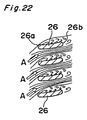
- the airflow enters between the blades 26, 26, ... of the outlet grille 25 from above, in the left-side area in a view toward the propeller fan 22 in Fig. 20, while the airflow enters between the blades 26, 26, ... of the outlet grille 25 from below, in the right-side area in a view toward the propeller fan 22.
- the states of the airflow passing through the blades in both the areas are illustrated as airflow lines in Figs. 21 and 22, respectively.
- airflow A having a downward component of velocity enters between the blades 26, the airflow A is greatly deflected upward by the blades 26, and airflow separation is therefore prone to occur on the lower surfaces (i.e., on the suction surfaces) of the blades 26, so that large vortexes are generated under the blades 26.
- airflow A having an upward component of velocity enters between the blades 26, airflow separation is prone to occur on the upper surfaces (i.e., on the suction surfaces) of the blades 26, so that large vortexes are generated over the blades.
- the invention employs the following arrangements:
- the invention provides an outdoor unit for use in an air conditioner comprising a casing, a propeller fan disposed in the casing, and an outlet grille disposed on an outlet side of the propeller fan, the outlet grille having a substantially quadrilateral outlet opening and having a plurality of blades disposed in parallel with one another at given intervals in the outlet opening, the outdoor unit for use in an air conditioner characterized in that, with respect to a plane which intersects with lines extending along lengths of the blades at a given angle in a rotational direction of the fan and which includes a central axis of the fan, a difference is provided between an inlet angle of portions of the blades positioned in an area on one side of the plane and an inlet angle of portions of the blades positioned in an area on the other side of the plane.
- the inlet angle of the portions of the blades positioned in the area on one side of the plane and the inlet angle of the portions of the blades positioned in the area on the other side of the plane can be respectively conformed to the directions of influx of swirl flow from the propeller fan.
- the inlet angle of the portions of the blades positioned in the area is set upward; in the area where the direction of influx of the swirl flow is upward, the inlet angle of the portions of the blades positioned in the area is set downward.
- a difference is provided between a chord length of the portions of the blades positioned in the area on the one side of the plane and a chord length of the portions of the blades positioned in the area on the other side of the plane.
- the chord length of the portions of the blades positioned in the area on one side of the plane and the chord length of the portions of the blades positioned in the area on the other side of the plane can be respectively conformed to the directions of influx of swirl flow from the propeller fan and to the direction of discharge from the outlet grille.
- the chord length of the portions of the blades positioned in the area where the direction of influx of the swirl flow is downward is set large to ensure a sufficient deflecting effect. Consequently, the airflow which has entered between the blades in the downward direction can be deflected sufficiently upward by the blades and thus can be discharged.
- chord length of the portions of the blades positioned in the area where the direction of influx of the swirl flow is upward is set small to make the effect of deflecting the entering airflow as small as possible. Consequently, the airflow which has entered between the blades in the upward direction can be discharged upward through the blades just as it was.
- the direction of discharge from the outlet grille is set downward, leftward, or rightward, the similar arrangement corresponding to each direction is provided. As a result, airflow separation on the suction surfaces of the blades subjected to the airflow is effectively restrained, although the airflow from the propeller fan is the swirl flow and makes different the directions of influx of the airflow at the portions of the blades.
- the turbulence in the discharged airflow can be prevented as completely as possible throughout the outlet opening of the outlet grille.
- aerodynamic noises are reduced, so that more quiet operation of the outdoor unit is achieved; additionally, the ventilating resistance at the outlet grille is reduced, so that the load for driving the fan is further reduced.
- the angle at which the plane intersects with the lines extending along the lengths of the blades is set within the range between 90° and 135°.
- the airflow forwarded as swirl flow from the propeller fan travels from the rear edges of the propeller fan to the front edges of the blades while rotating in the area between the rear edges of the propeller fan and the front edges of the blades.
- the plane generally coincides with the border between the area where the swirl flow actually enters between the front edges of the blades in a downward direction and the area where the swirl flow actually enters between the front edges of the blades in an upward direction, considering the angle through which the airflow rotates in the direction of the rotation of the fan between the instant when the airflow departs from the rear edges of the propeller fan and the instant when the airflow reaches the front edges of the blades. Accordingly, the above-mentioned effects of the invention can be achieved more reliably.
- shapes of rear edges toward the outside of the plurality of blades are the same throughout the outlet grille.
- the outdoor unit for use in an air conditioner achieves the above-mentioned effects of the invention and provides a good appearance in a view from the outside. Accordingly, the better appearance is achieved, the higher value of the outdoor unit as a commodity is expected.
- front edges of the plurality of blades are sawtoothed.
- a large number of small, vertical vortexes are generated from the roots of the sawteeth on the front edges of the blades, so that the airflow having high velocities of flow at large distances from the suction surfaces of the blades can be drawn close to the suction surfaces. Accordingly, airflow separation on the suction surfaces of the blades is effectively restrained, even though the inlet angles or chord length of the blades has a certain degree of deviation from the optimum values for the directions of influx of the airflow at the blade front edges. As a result, the above-mentioned effects of the invention are achieved more reliably.
- the sawtoothed shapes of the front edges of the blades are formed of a plurality of tapered projections.
- the tapered projections are shaped like right pyramids or right cones having apex portions thereof at the center of the thicknesses of the front edges of the blades.
- the deviation of the inlet angles or chord length of the blades from the optimum values for the directions of influx of the airflow at the blade front edges can be accommodated, whether the deviation is upward or downward.
- airflow separation on the suction surfaces of the blades is effectively and reliably restrained and the above-mentioned effects of the invention are thus achieved more reliably.
- the tapered projections are shaped like oblique pyramids or oblique cones having apex portions thereof in positions tilted in the direction of influx, relative to the center of the thicknesses of the front edges of the blades.
- the apex portions of the tapered projections are rounded.
- the tapered projections are readily manufactured and an improved safety in handling is ensured, as compared with the tapered projections shaped like spires.
- a ratio (H/L) of those values is set within the range between 0.05 and 0.35.
- a ratio (S/H) of those values is set within the range between 0.5 and 1.5.
- a ratio (S/H) of those values is set within the range between 0.7 and 1.3.
- the casing and the outlet grille are formed so that a position in which the outlet grille is installed can be changed so as to turn the direction of the lengths of the blades about the central axis of the fan.
- the direction of discharge from the outlet grille can be changed into upward, transverse, and other directions as required, by changing the position in which the outlet grille is installed and thereby turning the direction of the lengths of the blades about the central axis of the fan. Accordingly, the ability of the outdoor unit at installation is improved.
- the invention also provides an outdoor unit for use in an air conditioner comprising a casing, a propeller fan disposed in the casing, and an outlet grille disposed on an outlet side of the propeller fan, the outlet grille having a substantially quadrilateral outlet opening and having a plurality of blades disposed in parallel with one another at given intervals in the outlet opening, the outdoor unit for use in an air conditioner characterized in that, with respect to a plane which intersects with lengths of the blades at a given angle in a rotational direction of the fan and which includes a central axis of the fan, a difference is provided between a chord length of portions of the blades positioned in an area on one side of the plane and a chord length of portions of the blades positioned in an area on the other side of the plane.
- the chord length of the portions of the blades positioned in the area on one side of the plane and the chord length of the portions of the blades positioned in the area on the other side of the plane can be respectively conformed to the directions of influx of swirl flow from the propeller fan and to the direction of discharge from the outlet grille.
- the chord length of the portions of the blades positioned in the area where the direction of influx of the swirl flow is downward is set large to ensure a sufficient deflecting effect. Consequently, the airflow which has entered between the blades in the downward direction can be deflected sufficiently upward by the blades and thus can be discharged.
- chord length of the portions of the blades positioned in the area where the direction of influx of the swirl flow is upward is set small to make the effect of deflecting the entering airflow as small as possible. Consequently, the airflow which has entered between the blades in the upward direction can be discharged upward through the blades just as it was.
- the direction of discharge from the outlet grille is set downward, leftward, or rightward, the similar arrangement corresponding to each direction is provided. As a result, airflow separation on the suction surfaces of the blades subjected to the airflow is effectively restrained, although the airflow from the propeller fan is the swirl flow and makes different the directions of influx of the airflow at the portions of the blades.
- the turbulence in the discharged airflow can be prevented as completely as possible throughout the outlet opening of the outlet grille.
- aerodynamic noises are reduced, so that quiet operation of the outdoor unit is achieved.
- the ventilating resistance at the outlet grille is reduced, so that the load for driving the fan is reduced.13
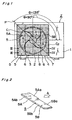
- Fig. 1 illustrates an outdoor unit Z in accordance with the first embodiment of the invention.
- the outdoor unit Z has a basic arrangement similar to that of the aforementioned conventional outdoor unit, in which arrangement a propeller fan 2 and a heat exchanger (not shown) are disposed in a casing 1 so as to face a square front opening 3 provided in the front surface of the casing and in which an outlet grille 4 is removably secured to the front opening 3.
- the outlet grille 4 has such a lattice-like shape as follows:
- the outlet grille 4 comprises an outer frame 7 having a substantially square outlet opening 8 on the inside thereof.
- a plurality of blades 5, 5, ... each shaped like a strip are disposed in horizontal position and in parallel with one another at given vertical intervals, and the plurality of blades 5, 5, ... are linked to one another by a plurality of support crosspieces 6, 6, ... disposed in vertical position.
- each of the blades 5, 5, ... has basically a curved section and is installed with its concave surface upward.
- an installed position in which the blades 5 extend vertically may be optionally selected instead of the installed position in which the blades 5 extend horizontally in general as shown in Fig. 1. Accordingly, in the installed position shown in Fig. 1, the airflow having outgone from the propeller fan 2 is deflected upward by the blades 5, 5, ... and is then discharged from the unit; in an installed position in which, for example, the blades 5 extend vertically with the concave surfaces of the blades 5 faced to the left in a view toward the propeller fan 2, the airflow from the propeller fan 2 is discharged in a leftward direction.
- each of the blades 5, 5, ... in the outlet grille 4 has a basic section similar to a section of a curved plate; in addition to such a basic section, this embodiment has different inlet angles of the blades 5, 5, ... in different areas defined according to the rotational direction of the propeller fan 2 and to the direction of the length of the blades 5, 5, ... .
- the whole area of the outlet opening 8 of the outlet grille 4 is divided into two areas C 1 and C 2 by an imaginary plane P (shown by a straight line in Fig. 1) including the central axis of the propeller fan 2, and the angle ⁇ (measured with respect to the rotational direction of the fan) at which the plane P intersects with lines extending along the lengths of the blades 5 is set within the range between 90° and 135° (Fig. 1 illustrates the arrangement in which the angle ⁇ of the intersection is 135°).
- each blade 5 is divided with respect to the direction of the length thereof into a first blade portion 5A positioned in the first outlet area C 1 and a second blade portion 5B positioned in the second outlet area C 2 so that an inlet angle ⁇ A of a front edge 5Aa of the first blade portion 5A and an inlet angle ⁇ B of a front edge 5Ba of the second blade portion 5B differ from each other.
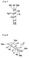
- the specific arrangement is as shown in Figs. 3 and 4.
- the inlet angle ⁇ A of the front edge 5Aa of the first blade portion 5A positioned in the first outlet area C 1 where the downward airflow enters is so set as to point upward relative to a horizontal line, according to the direction of influx of the airflow, so that the inlet angle ⁇ A matches the direction of influx of the airflow as satisfactorily as possible.
- the inlet angle ⁇ B of the front edge 5Ba of the second blade portion 5B positioned in the second outlet area C 2 where the upward airflow enters is so set as to point downward relative to a horizontal line, according to the direction of influx of the airflow, so that the inlet angle ⁇ B matches the direction of influx of the airflow as satisfactorily as possible.
- first blade portion 5A and the second blade portion 5B have different inlet angles ⁇ A , ⁇ B, as described above, the blade portions 5A and 5B have the same chord lengths L A , L B and the shapes of the rear edges 5Ab, 5Bb are also the same. Accordingly, the shapes of the rear edges of the blades 5, 5, ... are the same throughout the outlet grille 4 (i.e., throughout the outlet opening 8 of the outlet grille 4).
- the inlet angle ⁇ A of the first blade portion 5A and the inlet angle ⁇ B of the second blade portion 5B are respectively conformed to the directions of influx of the swirl flow from the propeller fan 2; therefore, the directions of influx of the airflow match the inlet angles ⁇ A and ⁇ B of the blades 5 as completely as possible in the first outlet area C 1 and the second outlet area C 2 , respectively, and thus airflow separation is effectively restrained on the negative pressure (suction) surfaces of the blades 5 subjected to the airflow, although the airflow from the propeller fan 2 is the swirl flow and makes different the directions of influx of the airflow at the portions 5A, 5B of the blades 5.
- the turbulence in the discharged airflow can be prevented as completely as possible throughout the outlet opening 8 of the outlet grille 4.
- aerodynamic noises are reduced, so that quiet operation of the outdoor unit Z is achieved.
- the ventilating resistance at the outlet grille 4 is reduced, so that the load for driving the fan is reduced.
- the first blade portions 5A and the second blade portions 5B have different inlet angles ⁇ A , ⁇ B but have the same shape in the rear edges 5Ab, 5Bb throughout the outlet grille 4, thus providing a good appearance in a view from the outdoor side. Accordingly, the better appearance is achieved, the higher value of the outdoor unit as a commodity is expected.
- Fig. 5 illustrates a blade 5 (designated by the same numeral for convenience) provided in the outlet grille 4.
- Fig. 6 illustrates a sectional view of first blade portions 5A, 5A, ... of the blades 5, 5, ... arranged in the first outlet area C 1
- Fig. 7 illustrates a sectional view of second blade portions 5B, 5B, ... arranged in the second outlet area C 2 .
- the other elements of the outdoor unit Z are the same as those of the first embodiment.
- the first blade portion 5A and the second blade portion 5B have the same basic shape in section which is similar to a section of a curved plate and have the same inlet angles ⁇ A , ⁇ B , while the first blade portion 5A and the second blade portion 5B have different chord lengths L A and L B , respectively. That is, the chord length L A of the first blade portion 5A positioned in the first outlet area C 1 is set large, while the chord lengths L B of the second blade portion 5B positioned in the second outlet area C 2 is set small.
- the large chord length L A of the first blade portion 5A ensures a sufficient effect of deflecting the airflow so that the airflow which has entered between the blades 5 in the downward direction can be deflected upward and thus can be discharged.
- the small chord length L B of the second blade portion 5B provides a decreased effect of deflecting the airflow so that the airflow which has entered between the blades 5 in the upward direction can be discharged upward from the blades just as it was.
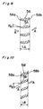
- Fig. 8 illustrates a blade 5 (designated by the same numeral for convenience) provided in the outlet grille 4.
- Fig. 9 illustrates a sectional view of first blade portions 5A, 5A, ... of the blades 5, 5, ... arranged in the first outlet area C 1
- Fig. 10 illustrates a sectional view of second blade portions 5B, 5B, ... arranged in the second outlet area C 2 .
- the other elements of the outdoor unit Z are the same as those of the first embodiment.
- first blade portion 5A and the second blade portion 5B have the same basic shape in section which is similar to a section of a curved plate, while the first blade portion 5A and the second blade portion 5B have different inlet angles ⁇ A , ⁇ B , and have different chord lengths L A and L B .
- the inlet angle ⁇ A of a front edge 5Aa of the first blade portion 5A positioned in the first outlet area C 1 where the airflow enters in a downward direction is so set as to point upward relative to a horizontal line, according to the direction of influx of the airflow, so that the inlet angle ⁇ A matches the direction of influx of the airflow as satisfactorily as possible.
- the inlet angle ⁇ B of a front edge 5Ba of the second blade portion 5B positioned in the second outlet area C 2 where the airflow enters in an upward direction is so set as to point downward relative to a horizontal line, according to the direction of influx of the airflow, so that the inlet angle ⁇ B matches the direction of influx of the airflow as satisfactorily as possible.
- the chord length L A of the first blade portion 5A positioned in the first outlet area C 1 is set large, while the chord lengths L B of the second blade portion 5B positioned in the second outlet area C 2 is set small.
- this embodiment has both the characteristics of the blades of the first and second embodiments, so as to exert both the operational effects of the first embodiment and the operational effects of the second embodiment. Accordingly, more quiet operation of the outdoor unit is achieved and the load for driving the fan is reduced.
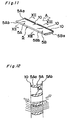
- FIG. 11 illustrates a blade 5 (designated by the same numeral for convenience) provided in the outlet grille 4.
- Fig. 12 illustrates a sectional view of first blade portions 5A, 5A, ... of the blades 5, 5, ... arranged in the first outlet area C 1
- Fig. 13 illustrates a sectional view of second blade portions 5B, 5B, ... arranged in the second outlet area C 2 .
- the other elements of the outdoor unit Z are the same as those of the first embodiment.
- the tapered projections 10, 10, ... are formed with a given pitch along the lengths of front edges 5Aa and 5Ba of blade portions 5A and 5B of the blade 5.
- the apex portion of each tapered projection 10 in this embodiment is shaped like a right pyramid positioned generally at the center of the thickness of the front edge 5Aa or 5Ba of the blade portion 5A or 5B.
- Such tapered projections 10, 10, ... are provided so that both the front edges 5Aa and 5Ba of the blade portions 5A and 5B have a sawtoothed shape.
- the tapered projections 10 shaped like regular cones accommodate the deviation of the inlet angles or chord length of the blades 10 from the optimum value(s) for the directions of influx of the airflow at the blade front edges 5Aa, 5Ba, whether the deviation is upward or downward, so that airflow separation on the negative pressure (suction) surfaces of the blades 5 is effectively restrained.
- the chord length of the blade 5 is given as L
- the height of the tapered projections 10 is given as H
- the pitch of the tapered projections 10, 10, ... is given as S.
- the relation between the ratio of the height H of the tapered projections 10 to the chord length L of the blade 5 and noise level i.e., one of the effects achieved by the restraint on airflow separation that the tapered projections 10 perform
- noise level i.e., one of the effects achieved by the restraint on airflow separation that the tapered projections 10 perform
- Fig. 17 illustrates air-volume/noise characteristics on the above embodiments in comparison with a prior art.
- a symbol ⁇ represents the characteristics of the prior art (Figs. 20 to 22); a symbol ⁇ represents the characteristics in the case that the blades of the prior art each comprising the tapered projections 10, 10, ... were used; a symbol ⁇ represents the characteristics of the first embodiment; and a symbol ⁇ represents the characteristics of the fourth embodiment. It is observed from the experimental data that the invention achieves quiet operation of the outdoor unit.
- Fig. 18 illustrates a sectional view of first blade portions 5A, 5A, ... arranged in the first outlet area C 1
- Fig. 19 illustrates a sectional view of second blade portions 5B, 5B, ... positioned in the second outlet area C 2
- the blades 5 of this embodiment represent a modification to the blades 5 of the fourth embodiment.
- a plurality of tapered projections 10, 10, ... on the front edges 5Aa and 5Ba of each blade 5 are shaped like right pyramids; in the fifth embodiment, by contrast, a plurality of tapered projections 10, 10, ...
- each blade 5 on front edges 5Aa and 5Ba of each blade 5 are shaped like oblique pyramids. More specifically, the apex portions of the tapered projections 10, 10, ... are in positions tilted in the direction of influx of the airflow forwarded to the blade 5, relative to the center of the thickness of the front edges 5Aa and 5Ba of the blade 5.
- the directions of influx of the airflow from the propeller fan 2 can be matched with the inlet angles ⁇ A and ⁇ B of the blades 5 as completely as possible in the first outlet area C 1 and the second outlet area C 2 , respectively.
- airflow having high velocities of flow at large distances from the suction surface of each blade 5 can be drawn close to the suction surface; as the synergy between these effects, more quiet operation can be achieved and the load for driving the fan can be further reduced.
- the tapered projections 10, 10, ... are provided on the front edges 5Aa and 5Ba of each blade 5 in which the first blade portion 5A and the second blade portion 5B have the same chord length and different inlet angles; however, the invention is not limited to such an arrangement.
- the tapered projections 10, 10, ... may be provided on front edges 5Aa and 5Ba of each blade 5 in which a first blade portion 5A and a second blade portion 5B have the same inlet angle and different chord lengths. In this arrangement also, the quiet operation can be achieved and the load for driving the fan can be reduced.
- each tapered projection 10 is shaped like a spire; however, the apex portion of each tapered projection 10 is not limited to such a shape but may be rounded. In the case that the apex portion of each tapered projection 10 is rounded, the tapered projections can be readily manufactured and an improved safety in handling is ensured, in comparison with the case that the apex portion is shaped like a spire.
- the sawtoothed front edges 5Aa and 5Ba of each blade 5 may be formed, e.g., simply by cutting in a zigzagged manner the blade front edges 5Aa and 5Ba which have the curved basic sections of the first to third embodiments, rather than by providing the tapered projections 10, 10, ... . That is, the blade front edges 5Aa and 5Ba have only to be sawtoothed in order that the airflow having high velocities of flow at large distances from the suction surface of each blade 5 may be drawn close to the suction surface.
- the outdoor unit for use in an air conditioner according to the invention can be preferably applied to an air conditioner, especially to an air conditioner of separate type having an indoor unit and an outdoor unit.
Landscapes
- Engineering & Computer Science (AREA)
- Mechanical Engineering (AREA)
- General Engineering & Computer Science (AREA)
- Chemical & Material Sciences (AREA)
- Combustion & Propulsion (AREA)
- Life Sciences & Earth Sciences (AREA)
- Sustainable Development (AREA)
- Other Air-Conditioning Systems (AREA)
- Structures Of Non-Positive Displacement Pumps (AREA)
Applications Claiming Priority (4)
| Application Number | Priority Date | Filing Date | Title |
|---|---|---|---|
| JP83759/97 | 1997-04-02 | ||
| JP9083759A JPH10281499A (ja) | 1997-04-02 | 1997-04-02 | 空気調和機用室外ユニット |
| JP8375997 | 1997-04-02 | ||
| PCT/JP1998/000636 WO1998044299A1 (fr) | 1997-04-02 | 1998-02-17 | Unite exterieure d'un conditionneur d'air de type separe |
Publications (3)
| Publication Number | Publication Date |
|---|---|
| EP0905455A1 true EP0905455A1 (fr) | 1999-03-31 |
| EP0905455A4 EP0905455A4 (fr) | 2000-04-05 |
| EP0905455B1 EP0905455B1 (fr) | 2003-05-02 |
Family
ID=13811504
Family Applications (1)
| Application Number | Title | Priority Date | Filing Date |
|---|---|---|---|
| EP98902248A Expired - Lifetime EP0905455B1 (fr) | 1997-04-02 | 1998-02-17 | Unite exterieure d'un conditionneur d'air |
Country Status (9)
| Country | Link |
|---|---|
| EP (1) | EP0905455B1 (fr) |
| JP (1) | JPH10281499A (fr) |
| KR (1) | KR20000015827A (fr) |
| CN (1) | CN1143094C (fr) |
| AU (1) | AU731727B2 (fr) |
| DE (1) | DE69813985T2 (fr) |
| ES (1) | ES2198043T3 (fr) |
| ID (1) | ID21819A (fr) |
| WO (1) | WO1998044299A1 (fr) |
Cited By (3)
| Publication number | Priority date | Publication date | Assignee | Title |
|---|---|---|---|---|
| EP2508815A1 (fr) * | 2011-04-08 | 2012-10-10 | TROX GmbH | Dispositif d'influence d'un flux d'air dans un composant d'une installation technique climatique |
| EP3805571A4 (fr) * | 2018-06-04 | 2021-05-26 | Mitsubishi Electric Corporation | Soufflante et dispositif à cycle de réfrigération |
| US12305879B2 (en) | 2019-07-02 | 2025-05-20 | Carrier Corporation | Cambered louvers |
Families Citing this family (12)
| Publication number | Priority date | Publication date | Assignee | Title |
|---|---|---|---|---|
| JP3804557B2 (ja) * | 2002-03-25 | 2006-08-02 | 三菱電機株式会社 | 空気調和機の室外機 |
| CN100348923C (zh) * | 2003-04-30 | 2007-11-14 | 乐金电子(天津)电器有限公司 | 相框式空调机的排出格栅 |
| CN100385180C (zh) * | 2005-04-05 | 2008-04-30 | 上海工程技术大学 | 干燥烘房的可调控引导送风系统 |
| JP4747822B2 (ja) * | 2005-12-14 | 2011-08-17 | ダイキン工業株式会社 | 空気調和機用室外機 |
| JP5322542B2 (ja) * | 2008-09-05 | 2013-10-23 | 三洋電機株式会社 | 空気調和装置の室外ユニット |
| JP5269155B2 (ja) * | 2011-07-15 | 2013-08-21 | 三洋電機株式会社 | 風向ガイドユニット、および、空気調和装置の室外ユニット |
| JP5269156B2 (ja) * | 2011-07-22 | 2013-08-21 | 三洋電機株式会社 | 風向ガイドユニット、および、空気調和装置の室外ユニット |
| US10273964B2 (en) * | 2015-07-30 | 2019-04-30 | WLC Enterprises, Inc. | Stepped-louvre heating, ventilating and air conditioning unit used in high-velocity, low speed fan |
| US10527046B2 (en) * | 2015-07-30 | 2020-01-07 | WLC Enterprises, Inc. | Stepped-louvre heating, ventilating and air conditioning unit used in high volume, low-speed fan |
| CN113251505B (zh) * | 2021-05-27 | 2024-11-15 | 珠海格力电器股份有限公司 | 一种出风格栅、出风组件及其控制方法和空调器 |
| KR20230127022A (ko) * | 2022-02-24 | 2023-08-31 | 삼성전자주식회사 | 송풍 장치 및 이를 포함하는 공기 조화기 |
| KR20250096313A (ko) * | 2023-12-20 | 2025-06-27 | 코웨이 주식회사 | 공기처리기 |
Family Cites Families (5)
| Publication number | Priority date | Publication date | Assignee | Title |
|---|---|---|---|---|
| US4976115A (en) * | 1989-08-21 | 1990-12-11 | Carrier Corporation | Cambered condenser grill |
| JP2924352B2 (ja) * | 1991-09-17 | 1999-07-26 | 松下電器産業株式会社 | 空気調和機の室外機用前面グリル |
| JPH0536220U (ja) * | 1991-10-09 | 1993-05-18 | ダイキン工業株式会社 | 空調装置の天吊室外機 |
| JPH05264070A (ja) * | 1992-03-17 | 1993-10-12 | Mitsubishi Electric Corp | 空気調和機の室外ユニット |
| JP3448136B2 (ja) * | 1994-11-08 | 2003-09-16 | 三菱重工業株式会社 | プロペラファン |
-
1997
- 1997-04-02 JP JP9083759A patent/JPH10281499A/ja active Pending
-
1998
- 1998-02-17 WO PCT/JP1998/000636 patent/WO1998044299A1/fr not_active Ceased
- 1998-02-17 ES ES98902248T patent/ES2198043T3/es not_active Expired - Lifetime
- 1998-02-17 CN CNB988004127A patent/CN1143094C/zh not_active Expired - Fee Related
- 1998-02-17 ID IDW980107D patent/ID21819A/id unknown
- 1998-02-17 AU AU58813/98A patent/AU731727B2/en not_active Ceased
- 1998-02-17 DE DE69813985T patent/DE69813985T2/de not_active Expired - Fee Related
- 1998-02-17 EP EP98902248A patent/EP0905455B1/fr not_active Expired - Lifetime
- 1998-02-17 KR KR1019980709377A patent/KR20000015827A/ko not_active Ceased
Cited By (4)
| Publication number | Priority date | Publication date | Assignee | Title |
|---|---|---|---|---|
| EP2508815A1 (fr) * | 2011-04-08 | 2012-10-10 | TROX GmbH | Dispositif d'influence d'un flux d'air dans un composant d'une installation technique climatique |
| EP3805571A4 (fr) * | 2018-06-04 | 2021-05-26 | Mitsubishi Electric Corporation | Soufflante et dispositif à cycle de réfrigération |
| US11397011B2 (en) | 2018-06-04 | 2022-07-26 | Mitsubishi Electric Corporation | Air-sending device and refrigeration cycle apparatus |
| US12305879B2 (en) | 2019-07-02 | 2025-05-20 | Carrier Corporation | Cambered louvers |
Also Published As
| Publication number | Publication date |
|---|---|
| AU731727B2 (en) | 2001-04-05 |
| KR20000015827A (ko) | 2000-03-15 |
| ES2198043T3 (es) | 2004-01-16 |
| JPH10281499A (ja) | 1998-10-23 |
| ID21819A (id) | 1999-07-29 |
| AU5881398A (en) | 1998-10-22 |
| CN1143094C (zh) | 2004-03-24 |
| CN1222965A (zh) | 1999-07-14 |
| EP0905455A4 (fr) | 2000-04-05 |
| DE69813985D1 (de) | 2003-06-05 |
| WO1998044299A1 (fr) | 1998-10-08 |
| DE69813985T2 (de) | 2004-02-19 |
| EP0905455B1 (fr) | 2003-05-02 |
Similar Documents
| Publication | Publication Date | Title |
|---|---|---|
| EP0905455A1 (fr) | Unite exterieure d'un conditionneur d'air de type separe | |
| JP3061026B2 (ja) | 空気調和機の室内機 | |
| JP5143173B2 (ja) | ターボファン及びこれを装備した空気調和機の室内機 | |
| JP2010133254A (ja) | 遠心送風機及びこれを備えた空気調和機 | |
| JP3052862B2 (ja) | 空気調和機用室外機 | |
| EP0844444B1 (fr) | Dispositif de conditionnement d'air avec une structure de sortie pour réduire le bruit de la turbulence de l'air | |
| HK1017418A (en) | Outdoor unit separate type air conditioner | |
| JP3240943B2 (ja) | 空気調和機の室内機 | |
| JPS61128038A (ja) | 空気調和装置 | |
| JP3444239B2 (ja) | 空気調和機用室外機 | |
| JPH05248662A (ja) | 空気調和装置の室外機 | |
| JP2762884B2 (ja) | 送風機構 | |
| CN119713550B (zh) | 用于空调的通风格栅、空调 | |
| JPH0443179B2 (fr) | ||
| JP3387840B2 (ja) | 空気調和装置の室内機 | |
| JPH0589899U (ja) | プロペラファンの吹出グリル構造 | |
| JPH0343557Y2 (fr) | ||
| JP3610585B2 (ja) | 空気調和機の室内ユニット | |
| JP6900033B2 (ja) | 気流拡散装置(拡散扇)及び空気調和機 | |
| JPH05195981A (ja) | クロスフローファン装置 | |
| JPH0261394A (ja) | 空気調和機および送風機保護ガード | |
| JPH07180855A (ja) | 空気調和装置 | |
| HK1009178B (en) | Air-conditioner having outlet structure for reducing air turbulence noise | |
| JPH01239391A (ja) | 空気調和機 | |
| JPH08193726A (ja) | 空気調和機 |
Legal Events
| Date | Code | Title | Description |
|---|---|---|---|
| PUAI | Public reference made under article 153(3) epc to a published international application that has entered the european phase |
Free format text: ORIGINAL CODE: 0009012 |
|
| 17P | Request for examination filed |
Effective date: 19981119 |
|
| AK | Designated contracting states |
Kind code of ref document: A1 Designated state(s): BE DE ES FR GB GR IT NL PT |
|
| A4 | Supplementary search report drawn up and despatched |
Effective date: 20000218 |
|
| AK | Designated contracting states |
Kind code of ref document: A4 Designated state(s): BE DE ES FR GB GR IT NL PT |
|
| RIC1 | Information provided on ipc code assigned before grant |
Free format text: 7F 24F 5/00 A, 7F 24F 13/08 B, 7F 24F 1/00 B, 7F 24F 13/075 B, 7F 24F 13/24 B |
|
| 17Q | First examination report despatched |
Effective date: 20020411 |
|
| GRAH | Despatch of communication of intention to grant a patent |
Free format text: ORIGINAL CODE: EPIDOS IGRA |
|
| RTI1 | Title (correction) |
Free format text: OUTDOOR UNIT OF AN AIR CONDITIONER |
|
| GRAH | Despatch of communication of intention to grant a patent |
Free format text: ORIGINAL CODE: EPIDOS IGRA |
|
| GRAA | (expected) grant |
Free format text: ORIGINAL CODE: 0009210 |
|
| AK | Designated contracting states |
Designated state(s): BE DE ES FR GB GR IT NL PT |
|
| PG25 | Lapsed in a contracting state [announced via postgrant information from national office to epo] |
Ref country code: BE Free format text: LAPSE BECAUSE OF FAILURE TO SUBMIT A TRANSLATION OF THE DESCRIPTION OR TO PAY THE FEE WITHIN THE PRESCRIBED TIME-LIMIT Effective date: 20030502 |
|
| REG | Reference to a national code |
Ref country code: GB Ref legal event code: FG4D |
|
| REF | Corresponds to: |
Ref document number: 69813985 Country of ref document: DE Date of ref document: 20030605 Kind code of ref document: P |
|
| PG25 | Lapsed in a contracting state [announced via postgrant information from national office to epo] |
Ref country code: GR Free format text: LAPSE BECAUSE OF FAILURE TO SUBMIT A TRANSLATION OF THE DESCRIPTION OR TO PAY THE FEE WITHIN THE PRESCRIBED TIME-LIMIT Effective date: 20030802 |
|
| PG25 | Lapsed in a contracting state [announced via postgrant information from national office to epo] |
Ref country code: PT Free format text: LAPSE BECAUSE OF FAILURE TO SUBMIT A TRANSLATION OF THE DESCRIPTION OR TO PAY THE FEE WITHIN THE PRESCRIBED TIME-LIMIT Effective date: 20030804 |
|
| REG | Reference to a national code |
Ref country code: ES Ref legal event code: FG2A Ref document number: 2198043 Country of ref document: ES Kind code of ref document: T3 |
|
| PG25 | Lapsed in a contracting state [announced via postgrant information from national office to epo] |
Ref country code: GB Free format text: LAPSE BECAUSE OF NON-PAYMENT OF DUE FEES Effective date: 20040217 |
|
| PG25 | Lapsed in a contracting state [announced via postgrant information from national office to epo] |
Ref country code: ES Free format text: LAPSE BECAUSE OF NON-PAYMENT OF DUE FEES Effective date: 20040218 |
|
| ET | Fr: translation filed | ||
| PLBE | No opposition filed within time limit |
Free format text: ORIGINAL CODE: 0009261 |
|
| STAA | Information on the status of an ep patent application or granted ep patent |
Free format text: STATUS: NO OPPOSITION FILED WITHIN TIME LIMIT |
|
| 26N | No opposition filed |
Effective date: 20040203 |
|
| PG25 | Lapsed in a contracting state [announced via postgrant information from national office to epo] |
Ref country code: NL Free format text: LAPSE BECAUSE OF NON-PAYMENT OF DUE FEES Effective date: 20040901 Ref country code: DE Free format text: LAPSE BECAUSE OF NON-PAYMENT OF DUE FEES Effective date: 20040901 |
|
| GBPC | Gb: european patent ceased through non-payment of renewal fee |
Effective date: 20040217 |
|
| PG25 | Lapsed in a contracting state [announced via postgrant information from national office to epo] |
Ref country code: FR Free format text: LAPSE BECAUSE OF NON-PAYMENT OF DUE FEES Effective date: 20041029 |
|
| NLV4 | Nl: lapsed or anulled due to non-payment of the annual fee |
Effective date: 20040901 |
|
| REG | Reference to a national code |
Ref country code: FR Ref legal event code: ST |
|
| PG25 | Lapsed in a contracting state [announced via postgrant information from national office to epo] |
Ref country code: IT Free format text: LAPSE BECAUSE OF NON-PAYMENT OF DUE FEES;WARNING: LAPSES OF ITALIAN PATENTS WITH EFFECTIVE DATE BEFORE 2007 MAY HAVE OCCURRED AT ANY TIME BEFORE 2007. THE CORRECT EFFECTIVE DATE MAY BE DIFFERENT FROM THE ONE RECORDED. Effective date: 20050217 |
|
| REG | Reference to a national code |
Ref country code: ES Ref legal event code: FD2A Effective date: 20040218 |
|
| REG | Reference to a national code |
Ref country code: HK Ref legal event code: WD Ref document number: 1017418 Country of ref document: HK |