EP0905599B1 - Manette de commande à contact multiple - Google Patents
Manette de commande à contact multiple Download PDFInfo
- Publication number
- EP0905599B1 EP0905599B1 EP98113543A EP98113543A EP0905599B1 EP 0905599 B1 EP0905599 B1 EP 0905599B1 EP 98113543 A EP98113543 A EP 98113543A EP 98113543 A EP98113543 A EP 98113543A EP 0905599 B1 EP0905599 B1 EP 0905599B1
- Authority
- EP
- European Patent Office
- Prior art keywords
- usual
- input device
- pressing
- contact
- switch
- Prior art date
- Legal status (The legal status is an assumption and is not a legal conclusion. Google has not performed a legal analysis and makes no representation as to the accuracy of the status listed.)
- Expired - Lifetime
Links
- 238000005192 partition Methods 0.000 claims description 20
- 230000007935 neutral effect Effects 0.000 claims description 9
- 230000003405 preventing effect Effects 0.000 claims description 9
- 230000002093 peripheral effect Effects 0.000 claims description 5
- 230000003247 decreasing effect Effects 0.000 claims description 4
- 238000009434 installation Methods 0.000 claims description 4
- 230000035807 sensation Effects 0.000 description 8
- 230000000694 effects Effects 0.000 description 4
- 239000012790 adhesive layer Substances 0.000 description 1
- 230000006870 function Effects 0.000 description 1
- 239000002184 metal Substances 0.000 description 1
- 229920003002 synthetic resin Polymers 0.000 description 1
- 239000000057 synthetic resin Substances 0.000 description 1
Images



Classifications
-
- G—PHYSICS
- G05—CONTROLLING; REGULATING
- G05G—CONTROL DEVICES OR SYSTEMS INSOFAR AS CHARACTERISED BY MECHANICAL FEATURES ONLY
- G05G9/00—Manually-actuated control mechanisms provided with one single controlling member co-operating with two or more controlled members, e.g. selectively, simultaneously
- G05G9/02—Manually-actuated control mechanisms provided with one single controlling member co-operating with two or more controlled members, e.g. selectively, simultaneously the controlling member being movable in different independent ways, movement in each individual way actuating one controlled member only
- G05G9/04—Manually-actuated control mechanisms provided with one single controlling member co-operating with two or more controlled members, e.g. selectively, simultaneously the controlling member being movable in different independent ways, movement in each individual way actuating one controlled member only in which movement in two or more ways can occur simultaneously
- G05G9/047—Manually-actuated control mechanisms provided with one single controlling member co-operating with two or more controlled members, e.g. selectively, simultaneously the controlling member being movable in different independent ways, movement in each individual way actuating one controlled member only in which movement in two or more ways can occur simultaneously the controlling member being movable by hand about orthogonal axes, e.g. joysticks
-
- H—ELECTRICITY
- H01—ELECTRIC ELEMENTS
- H01H—ELECTRIC SWITCHES; RELAYS; SELECTORS; EMERGENCY PROTECTIVE DEVICES
- H01H25/00—Switches with compound movement of handle or other operating part
- H01H25/04—Operating part movable angularly in more than one plane, e.g. joystick
-
- H—ELECTRICITY
- H01—ELECTRIC ELEMENTS
- H01H—ELECTRIC SWITCHES; RELAYS; SELECTORS; EMERGENCY PROTECTIVE DEVICES
- H01H2205/00—Movable contacts
- H01H2205/032—Several contacts formed in one plate or layer
- H01H2205/034—Several contacts formed in one plate or layer with snap action
-
- H—ELECTRICITY
- H01—ELECTRIC ELEMENTS
- H01H—ELECTRIC SWITCHES; RELAYS; SELECTORS; EMERGENCY PROTECTIVE DEVICES
- H01H2215/00—Tactile feedback
- H01H2215/034—Separate snap action
-
- H—ELECTRICITY
- H01—ELECTRIC ELEMENTS
- H01H—ELECTRIC SWITCHES; RELAYS; SELECTORS; EMERGENCY PROTECTIVE DEVICES
- H01H2215/00—Tactile feedback
- H01H2215/034—Separate snap action
- H01H2215/036—Metallic disc
Definitions
- the present invention relates to a multiple contact input device.
- the multiple contact input device according to the present invention comprises a first switch for being operated through a pushing motion of an operation member and a plurality of second switches for being operated by a swinging motion of the operation member.
- Such a multiple contact input device is useful as a pointing device employed for navigation systems or the like.
- a gazette of Japanese Utility Model Registration No. 2541120 has a description of a changeover switch device.
- a circular operation plate is swingingly moved, thereby enabling four switches disposed on four points at intervals of 90° to be selectively operated.
- a supporting shaft being a fulcrum for swinging movement is disposed on a center portion of the operation plate, four points at intervals of 90° at a periphery of the supporting shaft have respectively operation portions respectively corresponding to the four switches, and each stopper is disposed between the respective two adjacent operation portions. According to a direction of a force applied to the operation plate, the stopper exhibits an effect for interrupting the swinging movement of the operation plate, and such a swinging preventing effect by the stopper can prevent the two switches from being operated simultaneously.
- a gazette of Japanese Utility Model Laid-open No: 6-9025 has a description of a paddle switch.
- a circular key top plate is swingingly operated, thereby operating selectively four switches arranged on four points at intervals of 90°.
- a hole formed on a center of the key top plate is provided with a key top and the switches disposed on the center portion of the base are operated when the key top is pressed.
- the gazette has a description wherein a plate spring is employed so as to return the key top plate to a neutral position and the clicking plate is employed so as to return the key top.
- the second prior art for example, it is possible to output a coordinate signal through a swinging movement operation of the key top plate. Moreover, through the pressing operation of the key top, it is possible to output a point setting signal for generating a determination signal for deciding the previously input coordinate.
- the key top plate and the key top are independently required so as to output the coordinate signal and the point setting signal, thus causing problems such as hindering the number of the parts from being decreased and reducing the operation.
- a relatively long guide for guiding a pressing and returning motion of the key top is disposed at a peripheral surface of the hole formed on the key top plate so that the force may be applied to the key top in order to enable the key top plate to be swingingly moved. As a result, it is inconveniently limited to thin the guide by the second prior art.
- the first prior art makes only it possible to output the coordinate signal by means of the swinging movement operation of the operation plate.
- the first prior art makes it impossible to output the point setting signal. Therefore, it cannot be employed as a pointing device used for navigation system or the like.
- JP-A-07 282 689 A similar switch is described in JP-A-07 282 689.
- This switch comprises a rubber sheet having peripheral movable contacts which can be brought into contact with fixed contacts on a base board by inclining a key top. A protruded part at the center of the rubber sheet forms another contact.
- the key top is resiliently energized by the center part. By pushing the key top down the movable contacts and the center contacts are closed as shown in Fig. 4.
- a multi-wag flipping switch is disclosed with a click rubber member placed on a base plate.
- a housing mounted outher base plate having a central opening, a holding member mounted on the housing.
- Rotating members having one end rotatably are mounted on the holding member in such a wag that the second end can contact an upper surface of hollow protrusions of the click rubber member.
- an operating member pivotally mounted on the housing the rotating members can be individually pivoted to close the contacts positioned in the hollow pritusions.
- the present invention has been conducted in view of the above mentioned circumstances.
- the operation member is swingingly moved thereby pressing the each second switch corresponding to the each second pressing portion via the predetermined second pressing portion with the result that the second switch is switched between an opening state and a closing state.
- the coordinate signal can be output.
- a pressing force is applied to the operation member, thus pressing the first switch via the first pressing portion.
- the first switch is switched between an opening state and a closing state.
- one-side-members for example, projections
- another-side-members for example, receiving portions
- the first switch is opened or closed through a snapping motion of the first movable portion
- the each second switch is opened or closed through a snapping motion of the each second movable portion
- the operation member has a plate-shaped portion, and the plate-shaped portion is provided with the one first pressing portion, the plural second pressing portions and the plural one-side-members.
- the multiple contact input device comprises a spring member for touching the operation member thereby elastically and usually pressing the first pressing portion of the operation member against the first movable portion, and usually urging the operation member toward a neutral position set at a non-pressing position wherein the all second pressing members do not press the second movable positions.
- the spring member may be disposed on another portion.
- the case is formed by the base and a side wall raised on a periphery of the base, the case has a cover body fixed therein, a sheet is applied on an upper surface of the first movable portion and the second movable portion, there may be the spring member between the sheet and the plate-shaped portion of the operation member for elastically urging the operation member toward the cover body, and usually urging the operation member toward a neutral position set at a non-pressing position wherein the all second pressing members do not press the second movable positions.
- the operation member when the force is not applied to the operation member, the operation member is urged by the spring member, thereby being kept in a neutral position. Accordingly, the first movable portion of the first switch and the second movable portion of the second switch are kept in a non-pressure state.
- the multiple contact input device comprises each engaging mechanism for preventing the operation member from axially rotating.
- the each engaging mechanism may be provided with a recess formed on a periphery of the plate-shaped portion of the operation member, and a protrusion formed on the side wall of the case, and engaged with the recess.
- the each second switch comprises:
- the second pressing portions of the operation member can ensure usually pressing the second usual-opening contacts of the second switches.
- the first switch comprises the circular first movable portion made of a dome-shaped snap plate having a first usual-opening contact formed on a center portion thereof and a first usual-closing contact formed on a peripheral portion thereof, a first usual-closing fixing contact buried in the base for usually touching the first usual-closing contact, and a first usual-opening fixing contact buried in the base for corresponding to the first usual-opening contact.
- the second movable portion of the second switch is arranged so as to make a longitudinal direction of the second usual-opening contact and the second usual-closing contact correspond to a crossing direction with respect to a radial direction of the first movable portion.
- installation spaces of the first switch and the second switches are allowed to be small, thereby availing to promote miniaturizing the multiple contact input device.
- the first usual-closing fixing contact and the second usual-closing fixing contact may be unified as a common electrode.
- partitions for dividing a surface of the base into four sections at a periphery of an installation point of the first switch are disposed on four points of the base at intervals of 90° so as to protrude from the surface of the base, and a space surrounded by an inner end surfaces of the partitions is allocated to a portion for arranging the first movable portion, and each space between the respective two partitions adjacent to each other in a direction of arranging the partitions is allocated to each portion for arranging the second movable portions.
- the one-side-member is the projection
- the first pressing portion, the second pressing portion and the projection is subsequently decreased in a projecting length from the plate-shaped portion
- the another-side-member is the receiving member
- the receiving member is formed on the surface of the partition.
- the multiple contact input device can employ an arrangement wherein an aperture arranged on a center portion of the cover body is penetrated by an operation rod protruding to the center portion of the operation member, and the operation rod is protruded to an outer side of the cover body.
- the longitudinally both ends of the second usual-closing contact and the short circuit portions are bent by a folding line of a boundary portion thereof.
- the first movable portion may be formed by overlapping the two snap plates with each other.
- a single operation member enables respectively the first switch and a number of the second switches to be selectively switched. Therefore, the operation member can be used in common for controlling a coordinate signal and setting a point. In addition, it can provide a multiple contact input device for preventing the two switches from simultaneously operating, and as an effect, it can facilitate miniaturizing and thinning the multiple contact input device.
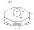
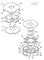
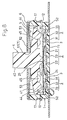
- a case 1 of the multiple contact input device is made of a synthetic resin-forming body integrally including a polygonal (for example, octagonal) base 11 and a side wall 12 raised at a periphery of the base 11.
- the base 11 of the case 1 is provided with a single first switch 2 and four second switches 3.
- the first switch 2 comprises a first usual-closing fixing contact 21 buried in a center portion of the base and having a surface of the switch exposed in approximately C-shaped, a first usual-opening fixing contact 22 buried in the base 11, and having a surface exposed on a center portion of the first usual-closing fixing contact 21, and a first movable portion 23.
- the first movable portion 23 made of a circular dome-shaped snap plate has first usual-closing contacts 24 at an outer periphery thereof and a spherical surface-shaped first usual-opening contact 25 extruded upward on a center portion thereof.
- the first movable portion 23 is mounted on the center portion of the base 11 so that the first usual-closing contact 24 may usually touch the first usual-closing fixing contact 21, and the first usual-opening contact 25 is opposed to the first usual-opening fixing contact 22.
- the first switch 2 has a structure wherein a top of the first movable portion 23 made of the snap plate is pushed downward, whereby the first usual-opening contact 25 touches the first usual-opening fixing contact 22 with a snapping motion, and the first usual-opening fixing contact 22 is electrically conducted to the first usual-closing fixing contact 21 via the first movable portion 23, thereby leading to a closing state.
- the first usual-opening contact 25 is separated from the first usual-opening fixing contact 22 with the snapping motion, the first usual-opening fixing contact 22 is electrically insulated from the first usual-closing fixing contact 21, thereby leading to an opening state.
- a sound and a touching sensation are made by the snapping motion of the snap plate.
- the second switches 3 are arranged on positions spaced from the first switch 2.
- the each second switch includes a second usual-closing fixing contact 31 buried in the base 11 and having an exposed surface, a second usual-opening fixing contact 32 buried in the base 11 and having an exposed surface and a second movable portion 33.
- the second movable portion 33 is rectangularly formed.
- the second usual-closing contacts 34, 34 made of a plate piece curved opposite to a second usual-opening contact 35 made of a curved plate piece are arranged on both sides of the second usual-opening contact 35 via slits 36, 36, and longitudinally both end portions of the second usual-opening contact 35 and the second usual-closing contacts 34, 34 are connected to each other via short circuit portions 37, 37.
- the second movable portion 33 is mounted on the base 11 so that the second usual-closing contact 34 may usually touch the second usual-closing fixing contact 31, and the second usual-opening contact 35 is opposed to the second usual-opening fixing contact 32.
- a top of the second movable portion 33 is pressingly lowered, whereby the second usual-opening contact 35 touches the second usual-opening fixing contact 32 with a snapping motion, and the second usual-opening fixing contact 32 is electrically conducted to the second usual-closing fixing contact 31 via the second movable portion 33 with the result that the second switch 3 is closed.
- the second usual-opening contact 35 is separated from the second usual-opening fixing contact 32 with the snapping motion and the second usual-opening fixing contact 32 is electrically insulated from the second usual-closing fixing contact 31 with the result that it is opened.
- a clicking sound and a touching sensation are made by the snapping motion of the snap plate.
- these clicking sound and touching sensation by the snapping motion of the snap plate are more clearly generated by including a bent folding line on each boundary portion between the longitudinally both end portions of the each second usual-closing contact 34 and the each short circuit portions 37.
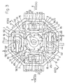
- the each second switch 3 is disposed on a plurality of peripheral portions positioned at regular intervals from the first switch 2. Namely, the second switches are disposed on four points around the first switch 2 at intervals of 90° . Moreover, the each second movable portion 33 of the four second switches 3 is disposed so as to make a longitudinal direction L (cf. Fig. 6) of the second usual-opening contact 35 and the second usual-closing contacts 34 correspond to a crossing direction with respect to a radial direction R of the first movable portion 23 of the first switch 2.
- the first usual-closing fixing contact 21 of the first switch 2 and the second usual-closing fixing contact 31 of the each second switch 3 are formed so as to be electrically short circuited by piercing a metal plate, as common electrodes.
- the base 11 of the case 1 is provided with partitions 13 for dividing a surface of the base 11 into four sections at a periphery of an installation point of the first switch 2 so that the partitions 13 may be disposed on four points of the base 11 at intervals of 90° so as to protrude from the surface of the base 11.
- a space S1 surrounded by an inner end surface 14 of the each partition 13 is allocated to a portion for arranging the first movable portion 23.
- each space S2 between the respective two adjacent partitions 13 is allocated to a portion for arranging the each second movable portion 33.
- a reference numeral 10 designates an insulating synthetic resin sheet.
- the sheet 10 is applied on an upper surface of the first movable portion 23, the second movable portions 33, the partitions 13 or the like via an adhesive layer, shown in Figs. 8 to 11.
- the sheet 10 is applied, thereby ensuring relationship of the positions of the first movable portion 23, the second movable portion 33, and the partitions 13.
- the operation member 4 is made of synthetic resin-forming body integrally including a polygonal (for example, octagonal) plate-shaped portion 41, and an operation rod 42 protruded upwardly from the center portion of the plate-shaped portion 41, and the plate-shaped portion 41 is housed by the case 1.
- a protrusive first pressing portion 43 is disposed on a center portion of a back surface of the plate-shaped portion 41.
- the first pressing portion 43 is supported by the top of the first movable portion 23 of the first switch 2, in a state wherein the sheet 10 is sandwiched therebetween (see Fig. 3).
- the back surface of the plate-shaped portion 41 has protrusive second pressing portions 44 on four points at intervals of 90° , equally spaced from the first pressing portion 43.
- the four second pressing portions 44 respectively correspond to the second usual-opening contacts 35 of the second movable portions 33 of the second switches 3, in a state of interposing the sheet 10 (see Fig. 3).
- each projection 45 is disposed on a middle portion between the respective two second pressing portions 44, 44 adjacent to each other in a direction of arranging the four second pressing portions 44.
- the projections 45 disposed at intervals of 90° are opposed to receiving portions 15 formed on the respective surface of the four partitions 13.
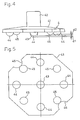
- the first pressing portion 43, the four second pressing portions 44 and the four projections 45 are decreased in that order in a projecting length from the plate-shaped portion 41.
- the first pressing portion 43 is more protrusive to a lower side by only d1 than the second pressing portion 44 and the second pressing portion 44 is protrusive to a lower side by only d2 than the projection 45.
- the difference d1 of a projecting length between the first pressing portion 43 and the second pressing portion 44 is predetermined so as to be equal to a stroke length of the first movable portion 23 made of the snap plate of the first switch 2 or a little more than the stroke length thereof. Therefore, as shown in Fig.
- a difference d2 of the projecting length between the second pressing portion 44 and the projection 45 is predetermined as below.
- the operation member 4 is swingingly moved whereby the two second pressing portions 44, 44 adjacent to each other are lowered in a direction of simultaneously pressing the two second usual-opening contacts 35, 35 of the two second movable portions 33, 33 corresponding thereto, the each projection 45 touches the receiving portion 15 with the result that the two second pressing portions 44 makes the two second usual-opening contacts 35 simultaneously reverse.
- the difference d2 is set so as to avoid that the two second pressing portions 44 make the two second usual-opening contacts 35 simultaneously reverse.
- a reference numeral 5 designates a spring member.
- the spring member 5 includes a center frame portion 52 having an aperture 51 and four arms 53 extending from the center frame portion 52 in a crossing state, a tip of the each arm 53 is buried in a recess 16 formed on an upper end surface of the side wall 12 of the case 1, thereby overlapping it with a bottom surface of the recess 16.
- a reference numeral 6 designates a cover body, the cover body 6 is fixed on the case 1 by engaging an engaging-checking piece 61 disposed on a periphery thereof with an engaging projection 17 on a side of the case 1. The cover body 6 closes an aperture of the case 1 as well as holding the tip of the each arm 53 of the spring member 5 in the recess 16.
- the operation rod 42 of the operation member 4 pierces the aperture 51 of the spring member 5 and a slightly large aperture 62 disposed on the center portion of the cover body 6 thereby protruding to an outer side of the cover member 6.
- the aperture 51 of the spring member 5 is formed in a square shaped hole, and the operation rod 42 is also formed in a square shape, whereby the aperture 51 of the spring 5 prevents the operation member from axially rotating via the operation rod 42.
- recesses 46, 46 formed on two points of a periphery of the plate-shaped portion 41 of the operation member 4 are engaged with two protrusions 18, 18 (see Fig. 3) formed on the side wall 12 of the case 1, thereby preventing the operation member 4 from axially rotating. Therefore, each engaging mechanism 7 for preventing the operation member 4 from axially rotating comprises the recess 46 and the protrusion 18.
- the center frame portion 52 of the spring member 5 elastically and lightly presses the plate-shape portion 41 of the operation member 4 downward. Therefore, when the force is not applied to the operation member 4, the pressing force is generated by the spring member 5, thereby keeping the operation member 4 in a neutral position so that an axis thereof may be vertical with respect to the base 11.
- the first usual-opening contact 25 touches the first usual-opening fixing contact 22 to switch the state of the first switch 2 from opening to closing.
- the touching sensation the feel
- the snapping motion of the first movable portion 23 is conveyed to a hand, at the same time while a clicking sound is made.
- the first usual-opening contact 25 is separated from the first usual-opening fixing contact 22 accompanied with the snapping motion of the first movable portion 23, thereby switching the first switch 2 from a closing state to an opening one. Also, in this case, the touching sensation accompanied with the snapping motion of the first movable portion 23 is conveyed to the hand at the same time while the clicking sound is made.
- the touching sensation accompanied with the snapping motion of the second usual-opening contact 35 is conveyed to the hand at the same time while the clicking sound is made.
- the second usual-opening contact 35 accompanied with the snapping motion thereof is separated from the second usual-opening fixing contact 32, thereby switching the second switch 2 from the closing state to the opening state.
- the touching sensation accompanied with the snapping motion of the second usual-opening contact 35 is conveyed to the hand, at the same time while the clicking sound is made.
- the first movable portion 23 may be formed by only one snap plate, needless to say.
- the first movable portion 23 are formed by overlapping the two snap plates, thereby achieving advantages wherein elasticity and strength of the first movable portion 23 is enhanced, and the clicking sound accompanied with the snapping motion is more clearly made at the same time while the touching sensation thereof conveyed to the hand is further clear.
- a crossing shaped plate spring is employed as the spring member
- a circular or polygonal (preferably octagonal) shaped plate spring may be employed.
- a position for arranging the spring member 5 is not limited to a portion between the operation member 4 and the cover body 6. Accordingly, it may be interposed between the sheet 10 and the plate-shaped portion 41 of the operation member 4.
- the spring member 5 having an upwardly protruding shape can be preferably employed.
- the receiving portion is disposed on the back side of the plate-shaped portion 41 of the operation member 4, and the projection corresponding to the receiving portion is disposed on a side of the case 1.
Landscapes
- Physics & Mathematics (AREA)
- General Physics & Mathematics (AREA)
- Engineering & Computer Science (AREA)
- Automation & Control Theory (AREA)
- Switches With Compound Operations (AREA)
- Push-Button Switches (AREA)
Claims (19)
- Un dispositif d'entrée à contacts multiples comprenant :un premier commutateur (2),plusieurs seconds commutateurs (3) disposés sur une pluralité de portions périphériques positionnés à intervalle régulier du premier commutateur,une base (11) incluant le premier commutateur (2) et les seconds commutateurs (3),un membre d'actionnement (4) incluant une première portion de pression (43) pour actionner le premier commutateur (2), plusieurs secondes portions de pression (44) correspondant à leurs seconds commutateurs respectifs (3) et où un premier membre partiel en forme ou d'une saillie (45) ou d'une portion de réception est disposé sur chaque position entre à chaque fois deux des seconde portions de pression (44) qui sont disposées sur le membre d'actionnement et adjacentes l'une à l'autre etun autre membre partiel en forme ou d'une saillie ou d'une portion de réception (14) disposé sur la base (11) pour toucher le membre partiel quand le membre d'actionnement (4) est balancé, et par là empêchant les deux portions de pression (44) sur les deux côtés du premier membre partiel de presser simultanément les seconds commutateurs (3) y correspondant et au même moment de connecter le premier commutateur par une opération de pression.
- Un dispositif d'entrée à contacts multiples selon la revendication 1, où le premier commutateur (2) est ouvert ou fermé à travers un mouvement par encliquetage d'une première portion mobile (23)
- Un dispositif d'entrée à contacts multiples selon la revendication 1, où les seconds commutateurs (3) sont ouverts ou fermés à travers un mouvement par encliquetage de chaque seconde portion mobile (33).
- Un dispositif d'entrée à contacts multiples selon la revendication 1, où le membre d'actionnement (4) a une portion en forme de plaque (41), où la portion en forme de plaque est fournie avec la première portion de pression (43), les plusieurs secondes portions de pression (44) et les plusieurs premiers membres partiels (45).
- Un dispositif d'entrée à contacts multiples selon la revendication 4, comprenant un membre ressort (5) pour toucher le membre d'actionnement (4) et ainsi pressant normalement la première portion de pression (43) du membre d'actionnement (4) élastiquement contre la première portion mobile (23), et poussant normalement le membre d'actionnement (4) vers une position neutre fixée à une position de non-actionnement où aucun des seconds membres de pression (44) ne pressent les secondes portions mobiles.
- Un dispositif d'entrée à contacts multiples selon la revendication 4, où un boîtier est formé par la base et une paroi latérale (12), debout sur la périphérie de la base, le boîtier a un corps de couverture fixé là-dedans, et où un panneau est posée sur une surface de la première portion mobile (23) et de la seconde portion mobile (33), et le membre ressort (5) est disposé entre la couverture et la portion en forme de plaque du membre d'actionnement (4) pour pousser le membre d'actionnement élastiquement vers le corps de couverture (6) et le membre d'actionnement (4) normalement vers une position neutre fixée à une position de non-actionnement où aucun des seconds membres de pression (44) ne pressent une des secondes portions mobiles.
- Un dispositif d'entrée à contacts multiples selon la revendication 1, comprenant un mécanisme de maintien une rotation axiale du membre d'actionnement (4).
- Un dispositif d'entrée à contacts multiples selon la revendication 7, où le boîtier inclut la base (11) et la paroi latérale (12) encore debout sur la périphérie de la base, et le mécanisme de maintien est fourni avec un évidemment sur la périphérie de la portion en forme de plaque (41) du membre d'actionnement (4), et une saillie (18) formée sur la paroi latérale du boîtier, et est engrené avec l'évidemment.
- Un dispositif d'entrée à contacts multiples selon la revendication 1, où les seconds commutateurs sont disposés en quatre points à intervalle de 90° et les autres membres partiels (45) sont disposés en quatre points à intervalle de 90°.
- Un dispositif d'entrée à contacts multiples selon la revendication 1, où chaque second commutateur (3) comprend :une seconde portion mobile rectangulaire (33) ayant un second contact normalement ouvrant (35) et des seconds contacts normalement fermant (34), les seconds contacts normalement fermant sont composés d'une pièce en tôle, qui est inclinée de manière opposée au second contact normalement ouvrant et est disposée de manière séparée des deux côtés des seconds contacts normalement ouvrants à travers des fentes (36), et où les deux extrémités dans une direction longitudinale du second contact normalement ouvrant (35) et des seconds contacts normalement fermant (34) sont connectés ensemble via chacune des portions de connexion,un second normalement fermant contact fixant (31) enfoncé dans la base et normalement touchant les second contacts normalement fermant (34), etun second normalement ouvrant contact fixant enfoncé dans la base et correspondant au second contact normalement ouvrant (35).
- Un dispositif d'entrée à contacts multiples selon l'une des revendications 1 ou 10, où le premier commutateur (2) comprend une première portion mobile (23) en forme d'anneau, qui est composée d'une un panneau forme de cloche et un premier contact normalement ouvrant (22) qui est formé dans une portion centrale de là, et un premier contact normalement fermé (21) qui est formé dans une périphérie de là, et un premier normalement fermé contact fixant, qui est enfoncé dans la base pour toucher le premier contact normalement fermé, et un premier normalement ouvrant contact fixant, qui est enfoncé dans la base pour correspondre au premier contact normalement ouvrant.
- Un dispositif d'entrée à contacts multiples selon la revendication 11, où la seconde portion mobile (33) du second commutateur (3) est disposée de sorte à faire correspondre une direction longitudinale du second contact normalement ouvrant (35) et du second contact normalement fermant (31) à une direction croisante relativement à une direction radiale de la première portion mobile (23).
- Un dispositif d'entrée à contacts multiples selon la revendication 11, où le premier normalement fermant contact fixant (21) et le second normalement fermant contact fixant (31) sont unifiés comme électrode commune.
- Un dispositif d'entrée à contacts multiples selon la revendication 11, où des partitions pour diviser une surface de la base en quatre sections au niveau d'une périphérie d'un point d'installation du premier commutateur (2) sont disposées en quatre points sur la base à intervalle de 90° de sorte à faire saillie de la surface de la base (11) et un espace entouré par une surface d'extrémité intérieure des partitions, est alloué à une portion pour arranger la première portion mobile (23), et chaque espace entre deux partitions adjacentes relativement à leur direction d'arrangement correspondante est alloué à chaque portion pour arranger chacune des secondes portions mobiles (33).
- Un dispositif d'entrée à contacts multiples selon la revendication 4, où le premier membre partiel est la projection (45), et la première portion de pression (43), la seconde portion de pression (44) et la projection en conséquence de quoi présentent une longueur de projection diminuée relativement à la portion en forme de plaque, pendant que l'autre membre partiel est le membre de réception, et le membre de réception est formé sur la surface de la partition.
- Un dispositif d'entrée à contacts multiples selon la revendication 6, où une ouverture disposée sur une portion centrale du corps de couverture est pénétrée par une barre d'actionnement qui s'étend de la portion centrale du membre d'actionnement et la barre d'actionnement s'étend sur la périphérie du corps de couverture.
- Un dispositif d'entrée à contacts multiples selon la revendication 5 ou 6, où le membre ressort (5) est composé d'un ressort feuilleté (23).
- Un dispositif d'entrée à contacts multiples selon la revendication 10, où dans la seconde portion mobile (33), les deux extrémités du second contact normalement fermant (34) longitudinalement et les portions de connexion sont courbées le long d'une ligne de pliage dans une portion frontière de là.
- Un dispositif d'entrée à contacts multiples selon la revendication 11, où la première portion mobile (23) est formée par recouvrement des deux panneaux l'un avec l'autre.
Applications Claiming Priority (3)
| Application Number | Priority Date | Filing Date | Title |
|---|---|---|---|
| JP26608897 | 1997-09-30 | ||
| JP26608897A JP3470022B2 (ja) | 1997-09-30 | 1997-09-30 | 多接点入力装置 |
| JP266088/97 | 1997-09-30 |
Publications (3)
| Publication Number | Publication Date |
|---|---|
| EP0905599A2 EP0905599A2 (fr) | 1999-03-31 |
| EP0905599A3 EP0905599A3 (fr) | 2003-11-12 |
| EP0905599B1 true EP0905599B1 (fr) | 2006-06-21 |
Family
ID=17426175
Family Applications (1)
| Application Number | Title | Priority Date | Filing Date |
|---|---|---|---|
| EP98113543A Expired - Lifetime EP0905599B1 (fr) | 1997-09-30 | 1998-07-21 | Manette de commande à contact multiple |
Country Status (6)
| Country | Link |
|---|---|
| US (1) | US6399904B1 (fr) |
| EP (1) | EP0905599B1 (fr) |
| JP (1) | JP3470022B2 (fr) |
| KR (1) | KR100328792B1 (fr) |
| DE (1) | DE69834991T2 (fr) |
| TW (1) | TW364136B (fr) |
Cited By (1)
| Publication number | Priority date | Publication date | Assignee | Title |
|---|---|---|---|---|
| CN104599888A (zh) * | 2013-11-01 | 2015-05-06 | 褚锦雄 | 五向位开关基座结构 |
Families Citing this family (46)
| Publication number | Priority date | Publication date | Assignee | Title |
|---|---|---|---|---|
| JP4018813B2 (ja) * | 1998-07-03 | 2007-12-05 | 富士通株式会社 | 携帯電話機 |
| JP2001283690A (ja) * | 2000-03-29 | 2001-10-12 | Hosiden Corp | 多接点入力装置 |
| JP2002008485A (ja) * | 2000-06-19 | 2002-01-11 | Matsushita Electric Ind Co Ltd | キー操作装置 |
| USD474247S1 (en) | 2000-06-27 | 2003-05-06 | Hosiden Corporation | Multi directional input apparatus |
| JP3890863B2 (ja) * | 2000-08-23 | 2007-03-07 | 松下電器産業株式会社 | 多方向操作スイッチ及びこれを用いた電子機器 |
| JP3925067B2 (ja) * | 2000-10-05 | 2007-06-06 | 松下電器産業株式会社 | 多方向入力装置およびこれを用いた電子機器 |
| JP2002248269A (ja) * | 2001-02-26 | 2002-09-03 | Mitsumi Electric Co Ltd | ゲームコントローラ用入力キー |
| JP4100879B2 (ja) * | 2001-03-12 | 2008-06-11 | アルプス電気株式会社 | 多方向入力装置 |
| JP2003045291A (ja) * | 2001-08-02 | 2003-02-14 | Fuji Photo Film Co Ltd | 操作ボタン構造 |
| US20030098842A1 (en) * | 2001-11-27 | 2003-05-29 | Shin Jiuh Corp. | Directional switch |
| US20030184522A1 (en) * | 2002-03-28 | 2003-10-02 | Takashi Mita | Text input device |
| JP4256685B2 (ja) | 2002-05-13 | 2009-04-22 | ポリマテック株式会社 | 多方向入力キーおよびキー入力装置 |
| JP4029701B2 (ja) * | 2002-09-09 | 2008-01-09 | 松下電器産業株式会社 | 多方向入力装置 |
| JP4055523B2 (ja) * | 2002-09-12 | 2008-03-05 | 松下電器産業株式会社 | 四方向操作スイッチ |
| KR20040041760A (ko) * | 2002-11-11 | 2004-05-20 | 미츠쿠 덴시 고교 가부시키가이샤 | 4방향 스위치 |
| EP1590132B1 (fr) * | 2003-02-07 | 2008-03-26 | Flytec AG | Couteau de poche pourvu d'un microprocesseur |
| USD510392S1 (en) * | 2003-07-21 | 2005-10-04 | Intec, Inc. | Audio accessory for an electronic device |
| JP2005122686A (ja) * | 2003-09-22 | 2005-05-12 | Ntt Docomo Inc | 入力キー及び入力装置 |
| JP2005242983A (ja) * | 2004-01-30 | 2005-09-08 | Ntt Docomo Inc | 入力キー及び入力装置 |
| JP2005209616A (ja) * | 2003-12-25 | 2005-08-04 | Alps Electric Co Ltd | 可動接点付シート及びこれを用いた押釦スイッチ |
| TW200534315A (en) * | 2004-04-09 | 2005-10-16 | Hon Hai Prec Ind Co Ltd | Push switch |
| USD553620S1 (en) * | 2004-11-04 | 2007-10-23 | 3 Dconnexion Gmbh | Input device for computer-controlled systems |
| TWI249952B (en) * | 2004-12-29 | 2006-02-21 | Tatung Co Ltd | A direction key structure of preventing correlating action |
| TWI255477B (en) * | 2005-01-07 | 2006-05-21 | Lite On It Corp | Touching rib disposed on the surface of the operation unit |
| JP4446925B2 (ja) | 2005-04-28 | 2010-04-07 | ホシデン株式会社 | スライド操作式スイッチ |
| TWI273468B (en) * | 2005-04-29 | 2007-02-11 | Benq Corp | Electronic apparatus with multi-function key capable of functioning well |
| JP4551274B2 (ja) | 2005-05-16 | 2010-09-22 | アルプス電気株式会社 | 多方向入力装置 |
| US20070068785A1 (en) * | 2005-09-26 | 2007-03-29 | Taiwan Pwl Corporation | Rocker level assembly |
| TWI271763B (en) * | 2005-11-11 | 2007-01-21 | Benq Corp | Slender keyswitch structure |
| TWM303478U (en) * | 2006-04-24 | 2006-12-21 | Hon Hai Prec Ind Co Ltd | Multi direction switch |
| CN201000845Y (zh) * | 2006-07-14 | 2008-01-02 | 富士康(昆山)电脑接插件有限公司 | 多方向开关 |
| ITMI20070397A1 (it) * | 2007-03-01 | 2008-09-02 | Campagnolo Srl | Dispositivo di comando per bicicletta e bicicletta che lo comprende |
| JP4360442B2 (ja) * | 2008-02-18 | 2009-11-11 | オムロン株式会社 | 入力装置及びこれを用いた電子機器 |
| US8053696B1 (en) * | 2008-03-31 | 2011-11-08 | Shan Chaing Lin | Electric connector switch |
| JP5505303B2 (ja) * | 2008-04-28 | 2014-05-28 | 日本電気株式会社 | 複合スイッチ及びそれを備えた携帯機器 |
| USD627745S1 (en) * | 2009-07-30 | 2010-11-23 | Hosiden Corporation | Switch |
| CN102480287A (zh) * | 2010-11-23 | 2012-05-30 | 富士康(昆山)电脑接插件有限公司 | 定位开关 |
| KR200464163Y1 (ko) | 2011-05-26 | 2012-12-14 | 금승호 | 다방향 스위치 |
| JP2015102953A (ja) * | 2013-11-22 | 2015-06-04 | 株式会社デンソー | 操作入力装置 |
| JP6323467B2 (ja) * | 2016-01-21 | 2018-05-16 | カシオ計算機株式会社 | キー構造及びそのキー構造を備える電子機器 |
| US20170263395A1 (en) * | 2016-03-10 | 2017-09-14 | Omron Automotive Electronics Co., Ltd. | Switch Cell Apparatus having a Non-Electrical Tactile Feedback Pad |
| JP6538108B2 (ja) * | 2017-05-23 | 2019-07-03 | 株式会社ユニバーサルエンターテインメント | 遊技機 |
| DE102017210254A1 (de) * | 2017-06-20 | 2018-12-20 | Zf Friedrichshafen Ag | Bedieneinrichtung für ein Lenkrad eines Fahrzeugs |
| DE102017215999A1 (de) * | 2017-09-11 | 2019-03-14 | Continental Automotive Gmbh | Bedienvorrichtung mit einer in mehrere Richtungen verkippbaren Handhabe mit haptischer Rückmeldung |
| GB201909472D0 (en) * | 2019-07-01 | 2019-08-14 | Agco Int Gmbh | Joystick |
| KR102661080B1 (ko) * | 2022-03-16 | 2024-04-25 | 강성준 | 설치면과 연속되는 평평한 면을 포함하는 히든 스위치 |
Family Cites Families (18)
| Publication number | Priority date | Publication date | Assignee | Title |
|---|---|---|---|---|
| US2849549A (en) * | 1956-11-13 | 1958-08-26 | Gen Motors Corp | Electric switch |
| US4408103A (en) * | 1982-01-06 | 1983-10-04 | Smith Engineering | Joystick operated multiple position switch |
| US4492830A (en) * | 1983-03-28 | 1985-01-08 | Wico Corporation | Joystick with single-leaf spring switch |
| US4501939A (en) * | 1983-11-04 | 1985-02-26 | Personal Peripherals Inc. | Digital joystick controller |
| US4753000A (en) * | 1983-12-19 | 1988-06-28 | Advanced Circuit Technology | Method of making snap action switches |
| US4795862A (en) * | 1986-12-12 | 1989-01-03 | United Technologies Automotive, Inc. | Method and apparatus for operating vehicle windows with a switch |
| US4913285A (en) * | 1987-03-09 | 1990-04-03 | Alps Electronic Co., Ltd. | Water-and-dust-proof push-button switch housing dummy terminal for air venting |
| JPH0518818Y2 (fr) * | 1988-02-08 | 1993-05-19 | ||
| US5055642A (en) * | 1989-06-20 | 1991-10-08 | Mitsuku Denshi Kogyo Kabushiki Kaisha | Push button switch |
| JP2541120Y2 (ja) | 1990-02-28 | 1997-07-09 | ソニー株式会社 | 切換えスイッチ装置 |
| JPH069025U (ja) | 1992-07-08 | 1994-02-04 | 帝国通信工業株式会社 | パドルスイッチ |
| EP0587406B1 (fr) * | 1992-09-09 | 1997-11-12 | Matsushita Electric Industrial Co., Ltd. | Dispositif d'interrupteur à poussoir à combinaison |
| US5689095A (en) * | 1993-09-20 | 1997-11-18 | Kabushiki Kaisha Tokai Rika Denki Seisakusho | Switching device |
| JPH07282689A (ja) * | 1994-04-14 | 1995-10-27 | Alps Electric Co Ltd | 多方向入力スイッチ |
| JP3315245B2 (ja) * | 1994-05-12 | 2002-08-19 | アルプス電気株式会社 | 多方向入力スイッチ |
| JP3219353B2 (ja) * | 1994-08-26 | 2001-10-15 | アルプス電気株式会社 | 回転操作型スイッチおよび多方向入力装置 |
| JP3430186B2 (ja) * | 1994-10-07 | 2003-07-28 | アルプス電気株式会社 | 複合操作型スイッチ装置 |
| US5744765A (en) * | 1995-06-19 | 1998-04-28 | Sumitomo Wiring Systems, Ltd. | Lever switch with support walls for supporting movable contact points and method of detecting an operating direction of a lever switch |
-
1997
- 1997-09-30 JP JP26608897A patent/JP3470022B2/ja not_active Expired - Fee Related
- 1997-12-22 TW TW086119524A patent/TW364136B/zh not_active IP Right Cessation
-
1998
- 1998-07-21 EP EP98113543A patent/EP0905599B1/fr not_active Expired - Lifetime
- 1998-07-21 DE DE69834991T patent/DE69834991T2/de not_active Expired - Lifetime
- 1998-07-22 US US09/119,603 patent/US6399904B1/en not_active Expired - Lifetime
- 1998-09-28 KR KR1019980040208A patent/KR100328792B1/ko not_active Expired - Fee Related
Cited By (2)
| Publication number | Priority date | Publication date | Assignee | Title |
|---|---|---|---|---|
| CN104599888A (zh) * | 2013-11-01 | 2015-05-06 | 褚锦雄 | 五向位开关基座结构 |
| CN104599888B (zh) * | 2013-11-01 | 2017-04-12 | 褚锦雄 | 五向位开关基座结构 |
Also Published As
| Publication number | Publication date |
|---|---|
| KR19990030196A (ko) | 1999-04-26 |
| US6399904B1 (en) | 2002-06-04 |
| HK1019100A1 (en) | 2000-01-21 |
| DE69834991D1 (de) | 2006-08-03 |
| JP3470022B2 (ja) | 2003-11-25 |
| EP0905599A2 (fr) | 1999-03-31 |
| TW364136B (en) | 1999-07-11 |
| DE69834991T2 (de) | 2007-02-08 |
| EP0905599A3 (fr) | 2003-11-12 |
| KR100328792B1 (ko) | 2002-05-09 |
| JPH11111119A (ja) | 1999-04-23 |
Similar Documents
| Publication | Publication Date | Title |
|---|---|---|
| US6399904B1 (en) | Multiple contact input device | |
| JP3951493B2 (ja) | 多方向操作スイッチおよびこれを用いた複合スイッチ | |
| US4520240A (en) | Four-way key switch control mechanism | |
| KR100479489B1 (ko) | 슬라이드조작식 스위치 | |
| EP1069581B1 (fr) | Interrupteur multi-directionnel et dispositif de commande | |
| US6162999A (en) | Multi-directional operating switch | |
| KR960008882A (ko) | 회전조작형 스위치 및 다방향입력장치 | |
| GB2331850A (en) | Multi-directional switch assenbly | |
| US7087848B1 (en) | Multi operating electronic component | |
| JP2779604B2 (ja) | キースイッチ | |
| JPH07307125A (ja) | 多方向入力スイッチ | |
| KR20030001354A (ko) | 전자 장치용 제어 디바이스 | |
| EP1208575B1 (fr) | Bouton multifonction monte a la cardan | |
| EP3582243B1 (fr) | Commutateur à quatre voies comprenant une structure de prévention de dysfonctionnement | |
| JPH10188738A (ja) | 多方向スイッチ | |
| EP0832786A2 (fr) | Construction d'un interrupteur composite | |
| HK1019100B (en) | A multiple contact joystick | |
| JP3937670B2 (ja) | 多方向操作スイッチ | |
| US3959618A (en) | Switch actuator rocker handle | |
| JPH0323625Y2 (fr) | ||
| JP4251703B2 (ja) | 多方向押圧型スイッチ | |
| JP3220093B2 (ja) | 電子機器のキー構造 | |
| JPH0637554Y2 (ja) | スイツチ装置 | |
| JPH01221830A (ja) | 操作パネルスイッチ | |
| JP3170187B2 (ja) | ステアリングコラムスイッチ |
Legal Events
| Date | Code | Title | Description |
|---|---|---|---|
| PUAI | Public reference made under article 153(3) epc to a published international application that has entered the european phase |
Free format text: ORIGINAL CODE: 0009012 |
|
| AK | Designated contracting states |
Kind code of ref document: A2 Designated state(s): AT BE CH CY DE DK ES FI FR GB GR IE IT LI LU MC NL PT SE |
|
| AX | Request for extension of the european patent |
Free format text: AL;LT;LV;MK;RO;SI |
|
| PUAL | Search report despatched |
Free format text: ORIGINAL CODE: 0009013 |
|
| AK | Designated contracting states |
Kind code of ref document: A3 Designated state(s): AT BE CH CY DE DK ES FI FR GB GR IE IT LI LU MC NL PT SE |
|
| AX | Request for extension of the european patent |
Extension state: AL LT LV MK RO SI |
|
| 17P | Request for examination filed |
Effective date: 20031128 |
|
| 17Q | First examination report despatched |
Effective date: 20040303 |
|
| AKX | Designation fees paid |
Designated state(s): DE FI FR GB NL |
|
| GRAP | Despatch of communication of intention to grant a patent |
Free format text: ORIGINAL CODE: EPIDOSNIGR1 |
|
| GRAS | Grant fee paid |
Free format text: ORIGINAL CODE: EPIDOSNIGR3 |
|
| GRAA | (expected) grant |
Free format text: ORIGINAL CODE: 0009210 |
|
| AK | Designated contracting states |
Kind code of ref document: B1 Designated state(s): DE FI FR GB NL |
|
| REG | Reference to a national code |
Ref country code: GB Ref legal event code: FG4D |
|
| REF | Corresponds to: |
Ref document number: 69834991 Country of ref document: DE Date of ref document: 20060803 Kind code of ref document: P |
|
| REG | Reference to a national code |
Ref country code: HK Ref legal event code: GR Ref document number: 1019100 Country of ref document: HK |
|
| ET | Fr: translation filed | ||
| PLBE | No opposition filed within time limit |
Free format text: ORIGINAL CODE: 0009261 |
|
| STAA | Information on the status of an ep patent application or granted ep patent |
Free format text: STATUS: NO OPPOSITION FILED WITHIN TIME LIMIT |
|
| 26N | No opposition filed |
Effective date: 20070322 |
|
| PGFP | Annual fee paid to national office [announced via postgrant information from national office to epo] |
Ref country code: FI Payment date: 20120711 Year of fee payment: 15 Ref country code: GB Payment date: 20120719 Year of fee payment: 15 |
|
| PGFP | Annual fee paid to national office [announced via postgrant information from national office to epo] |
Ref country code: FR Payment date: 20120806 Year of fee payment: 15 Ref country code: DE Payment date: 20120720 Year of fee payment: 15 |
|
| PGFP | Annual fee paid to national office [announced via postgrant information from national office to epo] |
Ref country code: NL Payment date: 20120719 Year of fee payment: 15 |
|
| REG | Reference to a national code |
Ref country code: NL Ref legal event code: V1 Effective date: 20140201 |
|
| GBPC | Gb: european patent ceased through non-payment of renewal fee |
Effective date: 20130721 |
|
| REG | Reference to a national code |
Ref country code: FR Ref legal event code: ST Effective date: 20140331 |
|
| PG25 | Lapsed in a contracting state [announced via postgrant information from national office to epo] |
Ref country code: NL Free format text: LAPSE BECAUSE OF NON-PAYMENT OF DUE FEES Effective date: 20140201 Ref country code: DE Free format text: LAPSE BECAUSE OF NON-PAYMENT OF DUE FEES Effective date: 20140201 Ref country code: FI Free format text: LAPSE BECAUSE OF NON-PAYMENT OF DUE FEES Effective date: 20130721 Ref country code: GB Free format text: LAPSE BECAUSE OF NON-PAYMENT OF DUE FEES Effective date: 20130721 |
|
| REG | Reference to a national code |
Ref country code: DE Ref legal event code: R119 Ref document number: 69834991 Country of ref document: DE Effective date: 20140201 |
|
| PG25 | Lapsed in a contracting state [announced via postgrant information from national office to epo] |
Ref country code: FR Free format text: LAPSE BECAUSE OF NON-PAYMENT OF DUE FEES Effective date: 20130731 |