EP0905736A1 - Module de controle programmable - Google Patents
Module de controle programmable Download PDFInfo
- Publication number
- EP0905736A1 EP0905736A1 EP98117741A EP98117741A EP0905736A1 EP 0905736 A1 EP0905736 A1 EP 0905736A1 EP 98117741 A EP98117741 A EP 98117741A EP 98117741 A EP98117741 A EP 98117741A EP 0905736 A1 EP0905736 A1 EP 0905736A1
- Authority
- EP
- European Patent Office
- Prior art keywords
- control module
- circuit
- housing
- subcircuit
- module according
- Prior art date
- Legal status (The legal status is an assumption and is not a legal conclusion. Google has not performed a legal analysis and makes no representation as to the accuracy of the status listed.)
- Granted
Links
- 239000003990 capacitor Substances 0.000 claims abstract description 22
- 230000001419 dependent effect Effects 0.000 claims description 6
- 230000001934 delay Effects 0.000 description 3
- 230000001681 protective effect Effects 0.000 description 3
- 230000003111 delayed effect Effects 0.000 description 2
- 238000009429 electrical wiring Methods 0.000 description 1
- 238000009434 installation Methods 0.000 description 1
- 238000004519 manufacturing process Methods 0.000 description 1
- 230000001105 regulatory effect Effects 0.000 description 1
- 238000011144 upstream manufacturing Methods 0.000 description 1
- 238000004804 winding Methods 0.000 description 1
Images
Classifications
-
- H—ELECTRICITY
- H02—GENERATION; CONVERSION OR DISTRIBUTION OF ELECTRIC POWER
- H02H—EMERGENCY PROTECTIVE CIRCUIT ARRANGEMENTS
- H02H3/00—Emergency protective circuit arrangements for automatic disconnection directly responsive to an undesired change from normal electric working condition with or without subsequent reconnection ; integrated protection
- H02H3/24—Emergency protective circuit arrangements for automatic disconnection directly responsive to an undesired change from normal electric working condition with or without subsequent reconnection ; integrated protection responsive to undervoltage or no-voltage
- H02H3/247—Emergency protective circuit arrangements for automatic disconnection directly responsive to an undesired change from normal electric working condition with or without subsequent reconnection ; integrated protection responsive to undervoltage or no-voltage having timing means
-
- H—ELECTRICITY
- H01—ELECTRIC ELEMENTS
- H01H—ELECTRIC SWITCHES; RELAYS; SELECTORS; EMERGENCY PROTECTIVE DEVICES
- H01H83/00—Protective switches, e.g. circuit-breaking switches, or protective relays operated by abnormal electrical conditions otherwise than solely by excess current
- H01H83/12—Protective switches, e.g. circuit-breaking switches, or protective relays operated by abnormal electrical conditions otherwise than solely by excess current operated by voltage falling below a predetermined value, e.g. for no-volt protection
-
- H—ELECTRICITY
- H01—ELECTRIC ELEMENTS
- H01H—ELECTRIC SWITCHES; RELAYS; SELECTORS; EMERGENCY PROTECTIVE DEVICES
- H01H71/00—Details of the protective switches or relays covered by groups H01H73/00 - H01H83/00
- H01H71/02—Housings; Casings; Bases; Mountings
- H01H71/0207—Mounting or assembling the different parts of the circuit breaker
- H01H71/0228—Mounting or assembling the different parts of the circuit breaker having provisions for interchangeable or replaceable parts
-
- H—ELECTRICITY
- H01—ELECTRIC ELEMENTS
- H01H—ELECTRIC SWITCHES; RELAYS; SELECTORS; EMERGENCY PROTECTIVE DEVICES
- H01H71/00—Details of the protective switches or relays covered by groups H01H73/00 - H01H83/00
- H01H71/02—Housings; Casings; Bases; Mountings
- H01H71/0264—Mountings or coverplates for complete assembled circuit breakers, e.g. snap mounting in panel
- H01H71/0271—Mounting several complete assembled circuit breakers together
Definitions
- the invention relates to a control module for a Undervoltage release that can be placed on a busbar.
- An undervoltage release in combination with a circuit breaker usually serves to protect cables in installations and systems against overload and short circuit.
- the circuit breaker includes a thermal release, e.g. in the form of a bimetal, which depends on the overload time delayed tripping, and an instantaneous tripping magnetic or electromagnetic release device for high Surge and short-circuit currents.
- the undervoltage release releases the circuit breaker if the mains voltage drops below a threshold or in the event of a power failure. This triggering takes place after exceeding one of the mechanical inertia system-dependent response time.
- the shortest possible response time ensures good protection for one through the circuit breaker arrangement to be protected. As you can see a short-term interruption for certain applications the power supply is not critical is common the possibility of influencing the response time and thus a variation of a tripping time delay of the undervoltage release wanted.
- one of the shutdown kinematics is one Circuit breaker associated shutdown device for Delayed shutdown at minimum voltage.
- the winding connections with are connected to a control circuit.
- the invention is based, the trigger time delay the task for an undervoltage release, especially for an undervoltage release coupled to a circuit breaker, to be made variable.
- this object is achieved by a control module in a separate one that can be placed on the busbars Housing in which an electronic circuit for Tripping time delay (delay element) is integrated.
- the delay element is from the undervoltage release mechanically independent and therefore freely attachable, so that the Delay time varied by the user in a simple manner can be.
- control module and thus a separately attachable delay element allows on the one hand a simplified structure of the undervoltage release, because its control electronics are integrated in the control module can be.
- control module can be within a complex circuit breaker arrangement z. B. also at one end the busbar, i.e. in the distributor. Since the Control module developed independently of the undervoltage release and can be made will be a significant reduction of development and manufacturing costs for both the undervoltage release as well as for the control module achieved itself.
- the electronic Circuit of the control module for tripping time delay in a first subcircuit a diode and preferably two capacitors connected to this on the cathode side.
- This can be made by appropriate outside the housing Connections on the control module individually or interconnected can be connected to the undervoltage release.
- two capacitors can be different Capacity values realized three different variants be by either one of the capacitors or a parallel connection of these two capacitors outside the case will be produced.
- the electronic circuit comprises in addition, a second sub-circuit for voltage limitation.
- a second sub-circuit for voltage limitation.
- the second subcircuit thus forms a protective circuit for the one that determines the tripping time delay first subcircuit.
- the circuit further expediently comprises a third Subcircuit preferably two capacitors with input terminal contacts are connected. Furthermore the third subcircuit has a direct connection the resistances of the second subcircuit to one on the housing provided clamping contact. This is the control module for different DC voltages and for AC voltage applicable.
- the internally wired components of the electronic circuit of the control module are on the input and output sides Terminal contacts connected in a corresponding Number of housing openings of the control module arranged and are accessible from the outside.
- Terminal contacts connected in a corresponding Number of housing openings of the control module arranged and are accessible from the outside.
- at least two, preferably also three, output-side terminal contacts provided, via which an electrical Connection to undervoltage release established can be.
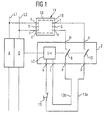
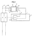
- Figure 1 shows a circuit breaker arrangement with an undervoltage release 2, the one with two line circuit breakers 4 and 6 and with two auxiliary contacts is coupled, the two switching paths 8 and 10 shown are.
- the undervoltage release 2 comprises a release device 12, which with the circuit breakers 4 and 6 and mechanically coupled to the auxiliary contacts 8, 10 is.
- the control module is on the output side 14 electrically connected to the undervoltage release 2.
- the output connection of the Control module 14 with the triggering device 12 of the undervoltage release 2 via its connections m, n and via the Switching paths 8, 10 and via connecting lines 13a, 13b, the connections o, p of the undervoltage release 2 connect to its connections k or l.
- control module 14 can be on the output side also directly via the connections k, l with the release device 12 be connected.
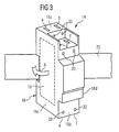
- the control module 14 contains in perspective in FIG 3 shown separate housing 16 an electronic Circuit or an electronic circuit 18 for Tripping time delay of undervoltage release 2 and to protect the protection provided for the tripping time delay Component (FIG 4 and 5).
- For electrical wiring of the control module 14 within the circuit breaker arrangement 2 to 6 comprises the control module 14 on the housing side accessible terminal contacts a to g, which in openings 20 at the Narrow sides 16a and 16b of the housing 16 arranged and over these are accessible.
- the housing 16 of the control module 14 in the direction of movement A on a busbar 22 in Form of a standard DIN rail can be attached.
- the housing 16 can with a usual housing of a low voltage or Shunt release to be identical, the one provided there Switch lock with switch knob led out of the housing can be omitted.
- the housing 16 is mechanically independent of the others the busbar 22 arranged switching elements or components 2 to 6 and therefore advantageously freely attachable. It is expediently arranged at one end of the busbar 22. The one resulting from the lack of the shift knob The opening can be closed with a cover.
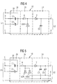
- Figures 4 and 5 show alternative variants of a delay element as part of the electronic circuit 18 of the Control module 14.
- the variants differ in principle on the one hand by the number of the tripping time delay realizing capacitors as well as the number of possible external connections of the terminal contacts a to g.
- the control module 14 comprises in a first subcircuit 24 of the electronic circuit 18 a single capacitor C3 for response time delay, the inside of the housing 16 on the one hand with the Terminal contact f and a rectifying diode V and on the other hand connected to the terminal contacts c and e is.
- a second sub-circuit 26 of the electronic Circuit 18 is the diode V connected upstream of the capacitor C3 on the anode side with a series resistor R and with a voltage-dependent one Resistor VDR1 connected, which in turn is connected to the terminal contacts c and e.
- the series resistor R forms with a capacitor C1 or C2 in one third divider circuit 28 a limiting element or RC element, that is connected to the terminal contacts a and b.
- the clamp contacts e and c can also be used to in addition to the capacitor C3 with the voltage dependent Resistor VDR1 to connect a capacitor C4.
- the two capacitors C3 and C4 are on the one hand the diode V is connected on the cathode side and with the terminal contact f connected. On the other hand, the capacitor C3 is with connected to the terminal contact e, while the capacitor C4 with the terminal contact g is connected.
- an input voltage U1 of 230V AC for the 110V variant of undervoltage release 2 makes contact the input voltage U1 - depending on the selected delay time - With the terminal contacts a and e on the input side or g, while in the 24V variant of the undervoltage release 2 the contacting of the terminal contacts on the input side b and e or g takes place. On the output side, different Tripping time delays or response times from the user be created by the undervoltage release 2 is connected to the terminal contacts f, g or f, e.
Landscapes
- Emergency Protection Circuit Devices (AREA)
- Regulation And Control Of Combustion (AREA)
- Breakers (AREA)
Applications Claiming Priority (2)
| Application Number | Priority Date | Filing Date | Title |
|---|---|---|---|
| DE19743038 | 1997-09-30 | ||
| DE19743038 | 1997-09-30 |
Publications (2)
| Publication Number | Publication Date |
|---|---|
| EP0905736A1 true EP0905736A1 (fr) | 1999-03-31 |
| EP0905736B1 EP0905736B1 (fr) | 2002-12-04 |
Family
ID=7844031
Family Applications (1)
| Application Number | Title | Priority Date | Filing Date |
|---|---|---|---|
| EP98117741A Expired - Lifetime EP0905736B1 (fr) | 1997-09-30 | 1998-09-18 | Module de controle programmable |
Country Status (4)
| Country | Link |
|---|---|
| EP (1) | EP0905736B1 (fr) |
| AT (1) | ATE229226T1 (fr) |
| DE (1) | DE59806511D1 (fr) |
| ES (1) | ES2189061T3 (fr) |
Cited By (1)
| Publication number | Priority date | Publication date | Assignee | Title |
|---|---|---|---|---|
| DE102011089211A1 (de) * | 2011-12-20 | 2013-01-31 | Siemens Aktiengesellschaft | Schalter, insbesondere Leistungsschalter für Niederspannungen |
Citations (3)
| Publication number | Priority date | Publication date | Assignee | Title |
|---|---|---|---|---|
| DE3912601A1 (de) * | 1988-04-18 | 1989-10-26 | Bassani Spa | Abschaltvorrichtung zum abschalten bei mindestspannung |
| EP0467504A2 (fr) * | 1990-07-16 | 1992-01-22 | International Business Machines Corporation | Appareil de traitement de données ayant un circuit anti-blocage |
| EP0473271A2 (fr) * | 1990-08-31 | 1992-03-04 | International Business Machines Corporation | Alimentation pour appareil de traitement de données |
-
1998
- 1998-09-18 AT AT98117741T patent/ATE229226T1/de not_active IP Right Cessation
- 1998-09-18 DE DE59806511T patent/DE59806511D1/de not_active Expired - Lifetime
- 1998-09-18 EP EP98117741A patent/EP0905736B1/fr not_active Expired - Lifetime
- 1998-09-18 ES ES98117741T patent/ES2189061T3/es not_active Expired - Lifetime
Patent Citations (3)
| Publication number | Priority date | Publication date | Assignee | Title |
|---|---|---|---|---|
| DE3912601A1 (de) * | 1988-04-18 | 1989-10-26 | Bassani Spa | Abschaltvorrichtung zum abschalten bei mindestspannung |
| EP0467504A2 (fr) * | 1990-07-16 | 1992-01-22 | International Business Machines Corporation | Appareil de traitement de données ayant un circuit anti-blocage |
| EP0473271A2 (fr) * | 1990-08-31 | 1992-03-04 | International Business Machines Corporation | Alimentation pour appareil de traitement de données |
Cited By (1)
| Publication number | Priority date | Publication date | Assignee | Title |
|---|---|---|---|---|
| DE102011089211A1 (de) * | 2011-12-20 | 2013-01-31 | Siemens Aktiengesellschaft | Schalter, insbesondere Leistungsschalter für Niederspannungen |
Also Published As
| Publication number | Publication date |
|---|---|
| ES2189061T3 (es) | 2003-07-01 |
| EP0905736B1 (fr) | 2002-12-04 |
| DE59806511D1 (de) | 2003-01-16 |
| ATE229226T1 (de) | 2002-12-15 |
Similar Documents
| Publication | Publication Date | Title |
|---|---|---|
| DE3525085A1 (de) | Einrichtung fuer ein kraftfahrzeug | |
| DE69019754T2 (de) | Fernsprechschutzmodul. | |
| DE3731361A1 (de) | Schalter mit einem in sich geschlossenen elektronischen ausloese-betaetigungsglied | |
| DE3911535A1 (de) | Elektrischer schalter | |
| DE69420923T2 (de) | Differentialschutzblock mit Kabeldurchgang | |
| DE10030954A1 (de) | Stromverteiler | |
| EP0905736B1 (fr) | Module de controle programmable | |
| DE2740744C2 (de) | Einrichtung zum Fernabschalten von Verbrauchern | |
| DE4326401C2 (de) | Anordnung bestehend aus einem Schalterteil und einem Sicherungsteil | |
| EP4068329B1 (fr) | Dispositif destiné à l'agencement sur barres de distribution comprenant un appareil de commutation et un composant électronique | |
| WO1995020257A1 (fr) | Disjoncteur de protection a courant differentiel residuel | |
| EP0262554A2 (fr) | Dispositif de connexion d'appareils d'installation aux barres de courant d'un système de base de barres omnibus | |
| DE10148863A1 (de) | Elektronisches Gerät | |
| DE2618288B2 (de) | Installations-Selbstschalter | |
| DE9105206U1 (de) | Gerätesteckeinheit | |
| EP1072077B1 (fr) | Alimentation d'une charge avec module antiparasites | |
| EP0026354B1 (fr) | Circuit pour des disjoncteurs multipolaires de courant de fuite | |
| DE3802324C2 (fr) | ||
| EP1721375B1 (fr) | Dispositif de protection destine a un branchement de recepteur | |
| DE102022212200B4 (de) | Verdrahtungsmodul zur internen Kontaktierung eines Hilfsschalters, Verdrahtungssystem und Verfahren zum elektrischen Kontaktieren eines solchen Verdrahtungsmoduls | |
| EP0352680B1 (fr) | Disjoncteur de protection pour courant de défaut | |
| DE102019112951B3 (de) | System zum Schutz einer elektrischen Quelle oder elektrischen Last | |
| AT390856B (de) | Vorrichtung zur gleichspannungswandlung einer eingangsspannung | |
| DE102022200296A1 (de) | Einpoliges Gehäusemodul und Niederspannungs-Schutzschaltgerät | |
| DE10146502A1 (de) | Elektrische Installationsverteilung |
Legal Events
| Date | Code | Title | Description |
|---|---|---|---|
| PUAI | Public reference made under article 153(3) epc to a published international application that has entered the european phase |
Free format text: ORIGINAL CODE: 0009012 |
|
| AK | Designated contracting states |
Kind code of ref document: A1 Designated state(s): AT BE DE ES GB IT |
|
| AX | Request for extension of the european patent |
Free format text: AL;LT;LV;MK;RO;SI |
|
| 17P | Request for examination filed |
Effective date: 19990820 |
|
| AKX | Designation fees paid |
Free format text: AT BE DE ES GB IT |
|
| GRAG | Despatch of communication of intention to grant |
Free format text: ORIGINAL CODE: EPIDOS AGRA |
|
| GRAG | Despatch of communication of intention to grant |
Free format text: ORIGINAL CODE: EPIDOS AGRA |
|
| GRAH | Despatch of communication of intention to grant a patent |
Free format text: ORIGINAL CODE: EPIDOS IGRA |
|
| 17Q | First examination report despatched |
Effective date: 20020614 |
|
| GRAH | Despatch of communication of intention to grant a patent |
Free format text: ORIGINAL CODE: EPIDOS IGRA |
|
| GRAA | (expected) grant |
Free format text: ORIGINAL CODE: 0009210 |
|
| AK | Designated contracting states |
Kind code of ref document: B1 Designated state(s): AT BE DE ES GB IT |
|
| REF | Corresponds to: |
Ref document number: 229226 Country of ref document: AT Date of ref document: 20021215 Kind code of ref document: T |
|
| REG | Reference to a national code |
Ref country code: GB Ref legal event code: FG4D Free format text: NOT ENGLISH |
|
| GBT | Gb: translation of ep patent filed (gb section 77(6)(a)/1977) |
Effective date: 20021204 |
|
| REF | Corresponds to: |
Ref document number: 59806511 Country of ref document: DE Date of ref document: 20030116 |
|
| REG | Reference to a national code |
Ref country code: ES Ref legal event code: FG2A Ref document number: 2189061 Country of ref document: ES Kind code of ref document: T3 |
|
| PGFP | Annual fee paid to national office [announced via postgrant information from national office to epo] |
Ref country code: AT Payment date: 20030820 Year of fee payment: 6 |
|
| PGFP | Annual fee paid to national office [announced via postgrant information from national office to epo] |
Ref country code: GB Payment date: 20030904 Year of fee payment: 6 |
|
| PGFP | Annual fee paid to national office [announced via postgrant information from national office to epo] |
Ref country code: BE Payment date: 20030916 Year of fee payment: 6 |
|
| PLBE | No opposition filed within time limit |
Free format text: ORIGINAL CODE: 0009261 |
|
| STAA | Information on the status of an ep patent application or granted ep patent |
Free format text: STATUS: NO OPPOSITION FILED WITHIN TIME LIMIT |
|
| 26N | No opposition filed |
Effective date: 20030905 |
|
| PG25 | Lapsed in a contracting state [announced via postgrant information from national office to epo] |
Ref country code: GB Free format text: LAPSE BECAUSE OF NON-PAYMENT OF DUE FEES Effective date: 20040918 Ref country code: AT Free format text: LAPSE BECAUSE OF NON-PAYMENT OF DUE FEES Effective date: 20040918 |
|
| PG25 | Lapsed in a contracting state [announced via postgrant information from national office to epo] |
Ref country code: BE Free format text: LAPSE BECAUSE OF NON-PAYMENT OF DUE FEES Effective date: 20040930 |
|
| BERE | Be: lapsed |
Owner name: *SIEMENS A.G. Effective date: 20040930 |
|
| GBPC | Gb: european patent ceased through non-payment of renewal fee |
Effective date: 20040918 |
|
| BERE | Be: lapsed |
Owner name: *SIEMENS A.G. Effective date: 20040930 |
|
| PGFP | Annual fee paid to national office [announced via postgrant information from national office to epo] |
Ref country code: DE Payment date: 20101119 Year of fee payment: 13 |
|
| PGFP | Annual fee paid to national office [announced via postgrant information from national office to epo] |
Ref country code: ES Payment date: 20111013 Year of fee payment: 14 |
|
| REG | Reference to a national code |
Ref country code: DE Ref legal event code: R119 Ref document number: 59806511 Country of ref document: DE Effective date: 20120403 |
|
| PG25 | Lapsed in a contracting state [announced via postgrant information from national office to epo] |
Ref country code: DE Free format text: LAPSE BECAUSE OF NON-PAYMENT OF DUE FEES Effective date: 20120403 |
|
| PGFP | Annual fee paid to national office [announced via postgrant information from national office to epo] |
Ref country code: IT Payment date: 20120927 Year of fee payment: 15 |
|
| REG | Reference to a national code |
Ref country code: ES Ref legal event code: FD2A Effective date: 20131022 |
|
| PG25 | Lapsed in a contracting state [announced via postgrant information from national office to epo] |
Ref country code: ES Free format text: LAPSE BECAUSE OF NON-PAYMENT OF DUE FEES Effective date: 20120919 |
|
| PG25 | Lapsed in a contracting state [announced via postgrant information from national office to epo] |
Ref country code: IT Free format text: LAPSE BECAUSE OF NON-PAYMENT OF DUE FEES Effective date: 20130918 |