EP0907098A1 - Digitale Kamera mit einer Bild/Zeichen Überlagerungsanzeigefunktion - Google Patents
Digitale Kamera mit einer Bild/Zeichen Überlagerungsanzeigefunktion Download PDFInfo
- Publication number
- EP0907098A1 EP0907098A1 EP98118589A EP98118589A EP0907098A1 EP 0907098 A1 EP0907098 A1 EP 0907098A1 EP 98118589 A EP98118589 A EP 98118589A EP 98118589 A EP98118589 A EP 98118589A EP 0907098 A1 EP0907098 A1 EP 0907098A1
- Authority
- EP
- European Patent Office
- Prior art keywords
- image
- photographic image
- luminance
- digital camera
- character
- Prior art date
- Legal status (The legal status is an assumption and is not a legal conclusion. Google has not performed a legal analysis and makes no representation as to the accuracy of the status listed.)
- Granted
Links
Images


Classifications
-
- G—PHYSICS
- G06—COMPUTING OR CALCULATING; COUNTING
- G06F—ELECTRIC DIGITAL DATA PROCESSING
- G06F3/00—Input arrangements for transferring data to be processed into a form capable of being handled by the computer; Output arrangements for transferring data from processing unit to output unit, e.g. interface arrangements
- G06F3/01—Input arrangements or combined input and output arrangements for interaction between user and computer
- G06F3/048—Interaction techniques based on graphical user interfaces [GUI]
- G06F3/0481—Interaction techniques based on graphical user interfaces [GUI] based on specific properties of the displayed interaction object or a metaphor-based environment, e.g. interaction with desktop elements like windows or icons, or assisted by a cursor's changing behaviour or appearance
- G06F3/0482—Interaction with lists of selectable items, e.g. menus
-
- G—PHYSICS
- G06—COMPUTING OR CALCULATING; COUNTING
- G06F—ELECTRIC DIGITAL DATA PROCESSING
- G06F3/00—Input arrangements for transferring data to be processed into a form capable of being handled by the computer; Output arrangements for transferring data from processing unit to output unit, e.g. interface arrangements
- G06F3/01—Input arrangements or combined input and output arrangements for interaction between user and computer
- G06F3/03—Arrangements for converting the position or the displacement of a member into a coded form
- G06F3/033—Pointing devices displaced or positioned by the user, e.g. mice, trackballs, pens or joysticks; Accessories therefor
- G06F3/0362—Pointing devices displaced or positioned by the user, e.g. mice, trackballs, pens or joysticks; Accessories therefor with detection of one-dimensional [1D] translations or rotations of an operating part of the device, e.g. scroll wheels, sliders, knobs, rollers or belts
-
- H—ELECTRICITY
- H04—ELECTRIC COMMUNICATION TECHNIQUE
- H04N—PICTORIAL COMMUNICATION, e.g. TELEVISION
- H04N1/00—Scanning, transmission or reproduction of documents or the like, e.g. facsimile transmission; Details thereof
- H04N1/0035—User-machine interface; Control console
- H04N1/00405—Output means
- H04N1/00408—Display of information to the user, e.g. menus
- H04N1/0044—Display of information to the user, e.g. menus for image preview or review, e.g. to help the user position a sheet
-
- H—ELECTRICITY
- H04—ELECTRIC COMMUNICATION TECHNIQUE
- H04N—PICTORIAL COMMUNICATION, e.g. TELEVISION
- H04N1/00—Scanning, transmission or reproduction of documents or the like, e.g. facsimile transmission; Details thereof
- H04N1/21—Intermediate information storage
- H04N1/2104—Intermediate information storage for one or a few pictures
- H04N1/2112—Intermediate information storage for one or a few pictures using still video cameras
- H04N1/2137—Intermediate information storage for one or a few pictures using still video cameras with temporary storage before final recording, e.g. in a frame buffer
-
- H—ELECTRICITY
- H04—ELECTRIC COMMUNICATION TECHNIQUE
- H04N—PICTORIAL COMMUNICATION, e.g. TELEVISION
- H04N23/00—Cameras or camera modules comprising electronic image sensors; Control thereof
- H04N23/60—Control of cameras or camera modules
- H04N23/63—Control of cameras or camera modules by using electronic viewfinders
- H04N23/631—Graphical user interfaces [GUI] specially adapted for controlling image capture or setting capture parameters
- H04N23/632—Graphical user interfaces [GUI] specially adapted for controlling image capture or setting capture parameters for displaying or modifying preview images prior to image capturing, e.g. variety of image resolutions or capturing parameters
-
- G—PHYSICS
- G09—EDUCATION; CRYPTOGRAPHY; DISPLAY; ADVERTISING; SEALS
- G09G—ARRANGEMENTS OR CIRCUITS FOR CONTROL OF INDICATING DEVICES USING STATIC MEANS TO PRESENT VARIABLE INFORMATION
- G09G2340/00—Aspects of display data processing
- G09G2340/12—Overlay of images, i.e. displayed pixel being the result of switching between the corresponding input pixels
- G09G2340/125—Overlay of images, i.e. displayed pixel being the result of switching between the corresponding input pixels wherein one of the images is motion video
-
- G—PHYSICS
- G09—EDUCATION; CRYPTOGRAPHY; DISPLAY; ADVERTISING; SEALS
- G09G—ARRANGEMENTS OR CIRCUITS FOR CONTROL OF INDICATING DEVICES USING STATIC MEANS TO PRESENT VARIABLE INFORMATION
- G09G5/00—Control arrangements or circuits for visual indicators common to cathode-ray tube indicators and other visual indicators
- G09G5/10—Intensity circuits
-
- G—PHYSICS
- G09—EDUCATION; CRYPTOGRAPHY; DISPLAY; ADVERTISING; SEALS
- G09G—ARRANGEMENTS OR CIRCUITS FOR CONTROL OF INDICATING DEVICES USING STATIC MEANS TO PRESENT VARIABLE INFORMATION
- G09G5/00—Control arrangements or circuits for visual indicators common to cathode-ray tube indicators and other visual indicators
- G09G5/36—Control arrangements or circuits for visual indicators common to cathode-ray tube indicators and other visual indicators characterised by the display of a graphic pattern, e.g. using an all-points-addressable [APA] memory
- G09G5/39—Control of the bit-mapped memory
- G09G5/395—Arrangements specially adapted for transferring the contents of the bit-mapped memory to the screen
-
- H—ELECTRICITY
- H04—ELECTRIC COMMUNICATION TECHNIQUE
- H04N—PICTORIAL COMMUNICATION, e.g. TELEVISION
- H04N2101/00—Still video cameras
-
- H—ELECTRICITY
- H04—ELECTRIC COMMUNICATION TECHNIQUE
- H04N—PICTORIAL COMMUNICATION, e.g. TELEVISION
- H04N2201/00—Indexing scheme relating to scanning, transmission or reproduction of documents or the like, and to details thereof
- H04N2201/32—Circuits or arrangements for control or supervision between transmitter and receiver or between image input and image output device, e.g. between a still-image camera and its memory or between a still-image camera and a printer device
- H04N2201/3285—Circuits or arrangements for control or supervision between transmitter and receiver or between image input and image output device, e.g. between a still-image camera and its memory or between a still-image camera and a printer device using picture signal storage, e.g. at transmitter
- H04N2201/3295—Deletion of stored data; Preventing such deletion
Definitions
- This invention relates to digital cameras and, more particularly, to a digital camera which is adapted to superpose character images on a photographic image being displayed, for example, on an LCD, according to a character display command.
- a digital camera comprising: an image monitor; a display means which displays a photographic image on said image monitor; an input means which inputs a character display command; a superposing means which superposes a character image on the photographic image in response to the character display command; and a first luminance reducing means which reduces a luminance of the photographic image in response to the character display command.
- the superposing means superposes a character image on the photographic image in response to the character display command. Also, the first luminance reducing means lowers the luminance of the photographic image in response to the character display command.
- the photographic image is a still image reproduced from a memory.
- the luminance of the photographic image lowered by the first luminance reducing means is increased by the first luminance increasing means for a predetermined time period from a start of renewing the photographic image by the renewing means.
- image data of the photographic image compressed by a predetermined method is stored in a memory.
- This compressed image data is decompressed by the predetermined method by a decompressing means during renewal.
- a display suspending means suspends display of the character and the photographic image prior to renewal.
- the character suspended of display is redisplayed by the character redisplay means after a lapse of a predetermined time period.
- the predetermined time period is a time period requiring the renewal.
- the first enabling means if an erasing means erases the photographic image recorded in the memory, the first enabling means enables the enabling means.
- the second enabling means enables the renewing means.
- the canceling means cancels the display of the character image
- the second luminance increasing means increases the luminance of the photographic image
- the character image displayed on the image monitor is reduced according to the character display command, the character image is easy to recognize.
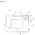
- a digital camera 10 of this embodiment includes a liquid crystal display (LCD) 14 provided in a back surface of a main body 12 to display photographic images.
- An image switching button 16 is arranged at a location of upper right with respect to the LCD 14. In a reproduce mode, if this image switching button 16 is operated while a desired photographic image (still image) is being reproduced from a memory card 70 shown in Figure 8, renewal is made for the photographic image being displayed on the LCD 14. That is, if a + button 16a is depressed once, a photographic image next to the current photographic image is reproduced from the memory card 70. If a - button 16b is depressed once, a photographic image preceding to the current photographic image is reproduced from the memory card 70.
- photographic images are displayed in real time on the LCD. Further, when a shutter button 22 provided on a top surface of the main body 12 is operated, a photographic image taken is recorded on the memory card 70.
- photographic image means a still image to be reproduced from the memory card 70 in the reproduce mode, besides real-time motion images taken in the camera mode.
- a main switch 18 is arranged on a right face of the main body 12. This main switch 18 is configured as shown in Figure 2(A), wherein if "OFF" is aligned to a mark provided on the side face, power supply is turned off. If “PLAY” is aligned to the mark 20, a reproduce mode is established, while a camera mode is established when "REC" is positioned to the mark 20.
- a menu button 24 of a dial type is also provided on the side face of the main body 12.
- this menu button 24 is depressed once in a direction toward the main body 12, an icon indicative of a menu is superposed and displayed on the LCD 14.
- the menu button 24 is rotated leftward, a cursor moves in a direction from right to left or from bottom to top. If the menu button 24 is rotated rightward, the cursor moves from left to right or from top to bottom. If the menu button 24 is depressed when the cursor is pointing at a desired icon, the icon designated by the cursor is selected.
- menu is displayed in this way.
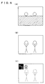
- the photographic image (motion image) on the LCD 14 is reduced in luminance during displaying the menu. That is, the luminance of the photographic image is at a normal level before performing superposition of a menu on the LCD 14 in accordance with operation of the menu button 24.
- icons are displayed as shown in Figure 3(A) and at the same time the luminance level of the photographic image is lowered. If a cancel button 26 provided lower left of the LCD 14, shown in Figure 1, is depressed, the menu display is cancelled and the luminance of the photographic image returns to the normal level.
- the luminance level of a photographic image is lowered during displaying character images, such as icons or letters. Accordingly, the character and photographic images are clearly distinguished from each other facilitating recognition of the character image.
- image renewal is made in the procedure as shown in Figure 6. That is, a black image is first displayed on the LCD 14 and then a renewal image with a normal luminance level is rendered little by little from the above. Then, the luminance level is lowered upon completion of the rendering, and "dust box” and “key” icons are put into display. Note that image switching is possible also in a display state of Figure 4(A) or (B) or Figure 7(A) or (B).
- the luminance of the photographic image is reduced during displaying the character image, facilitating recognition of the character.
- the digital camera 10 is structured in detail as shown in Figure 8. That is, a subject optical image is taken by a CCD imager 34 through a lens 30 and a complementary filter 32 of a mosaic type. In the camera mode, the CCD imager 34 performs a well-known pixel-mixing readout to provide a pixel signal to a CDS/AGC circuit 36.
- the CDS/AGC circuit 36 subjects the input pixel signal to well-known noise removal and level adjustment.
- the pixel signal processed by this CDS/AGC circuit 36 is converted by an A/D converter 38 into digital data or pixel data. This pixel data is processed of color separation and YUV conversion by a first signal processing circuit 40.
- a system controller 66 causes a selector 44 to select an input terminal 44a. Consequently, the YUV data obtained in the first signal processing circuit 40 is written into a memory area 48a of a DRAM 48 through buses 42 and 74.
- the CCD imager 34 adopts a progressive scan method, while an LCD 14 utilizes an interlace scan method. Due to this, the YUV data is temporarily written into the memory area 48a in order to convert the scanning process.
- the YUV data stored in the memory area 48a is read out by the interlace scan method and outputted to a second signal processing circuit 52 through the bus 50.
- the second signal processing circuit 52 creates C data and Y data from the YUV data thus inputted, and supplies the C data to a D/A converter 58 and the Y data to a luminance adjusting circuit 54.
- the luminance adjusting circuit 54 is controlled by a CPU 46 to thereby deliver a desired luminance level of the Y data to a D/A converter 60 through a switch SW1.
- a character generator 56 outputs icons as shown in Figures 3 and 4, a key mark as shown in Figure 7, key marks as shown in Figures 5 and 7, and character data such as of letters as shown in Figures 5 and 7.
- the switch SW1 is supplied also with this character data.
- the switch SW1 selects either one of the Y data or the character data under the control of the CPU 28.
- the C data outputted from the D/A converter 58 and the Y data or character data outputted from the D/A converter 60 are added together by an adder 64 so that an output of the adder is given to a terminal 62 and inputted as a motion image to the LCD 14. Consequently, only a photographic image is displayed on the LCD 14 before depressing the menu button 24. After depressing the menu button 24, the photographic image is superposed thereupon with character images such as icons or letters.
- the system controller 66 controls the CCD imager 34 to carry out so-called all-pixel readout. This causes the CCD imager 34 to output pixel signals fine by line.
- the CDS/AGC circuit 36 performs noise removal and level adjustment on the pixel signal in a manner similar to the above.
- the A/D converter 38 converts the pixel signal from the CDS/AGC circuit 36into digital data, or pixel data.
- the CCD imager 34 is disabled after outputting 1 frame of the pixel signals.
- the 1-frame pixel data i.e. photographic image data of a still image, is supplied directly onto the bus 42 without being processed by the first signal processing circuit 40.
- the selector 44 at this time has a selected terminal 44a so that the photographic image data is written into the memory area 48a.
- the CPU 46 performs YUV-conversion on the photographic image data in the memory area 48a with using a work area 48b, and compresses the converted YUV data, or the photographic image data, according to a JPEG format.
- the compressed image data is recorded onto a memory card 70 through the buses 72 and 68.
- the selector 44 selects the terminal 44b. Due to this, the CPU 46 reads out desired compressed image data, and decompresses the compressed image data with using the work area 48b.
- the decompressed photographic image data (YUV data) is stored in the memory area 48a, and thereafter read out therefrom.
- the second signal processing circuit 52 and subsequent operate in the above stated manner, to thereby display a desired photographic image (reproduced image) and desired character images on the LCD 14.
- the CPU 46 in the camera mode processes a flowchart shown in Figure 9.
- a subject motion image for example as shown in Figure 3 is displayed at a normal luminance level.
- a step S3 it is determined whether the menu button 24 is depressed or not. If "NO”, this luminance state is maintained, while if "YES”, the luminance adjusting circuit 54 is controlled at a step S5 to reduce the luminance level.
- a menu shown in Figure 3(A) is displayed on the LCD 14.
- the switch SW1 is connected to the side of the character generator 56 only when the icon is to be displayed, i.e., only when outputting icon character data representative of a resolution or icon character data representative of a flash mode from the character generator 56. Due to this, icons and a subject image are displayed with a reduced luminance level on the LCD 14 as shown in Figure 3(A).
- the CPU 46 subsequently determines at a step S9 whether a flash mode or a desired resolution mode is selected or not. If "YES”, the mode is set at a step S11 and the process proceeds to a step S15. At the step S15 the display of the menu is suspended, and the luminance level is increased at a step S17, and the process returns to the step S3. Specifically, the CPU 46 causes at the step S15 the switch SW1 to be connected at all times to the luminance adjusting circuit 54 side, and controls the luminance adjusting circuit 54 at a step S17 to bring the luminance level back to the normal level. Meanwhile, if "NO” at the step S9, it is determined at a step S13 whether the cancel button 26 has been depressed or not. If “NO” here, the process returns to the step S9, while if "YES", the process advances to the step S15.
- the CPU 46 in the reproduce mode processes flowchart shown in Figures 10 through 13. That is, at a step S21 a still reproduced image, for example as shown in Figure 4, is displayed at a normal luminance level. Then, it is determined at a step S23 whether the menu button 24 is depressed or not. If “NO” here, it is determined at a step S25 whether the image switching button 16 is operated or not. If “NO”, the process returns to the step S23. However, if "YES” at the step S25, a renewed image is displayed on the LCD 14 at the step S27, and the process returns to the step S23.
- the reproduced image is reduced in luminance level at a step S29, and icons of "dust box” and “key” are displayed at the upper left on the LCD 14 at a step S31. Accordingly, an image as shown in Figure 4(A) is displayed on the LCD 14. Specifically, the switch SW1 is connected to a character generator 56 side only when the character data for these two icons is outputted from the character generator 56.
- a step S33 the CPU 46 determines whether the erase mode has been selected or not. If “YES” here, the CPU 46 at a step S35 outputs letter data shown in Figure 5(A), and determines whether "NO” displayed on the LCD 14 has been selected at a step S37. If “YES” is determined, the process returns to the step S31, thereby displaying an image as shown in Figure 4(A) on the LCD 14. On the other hand, if "NO" is determined at the step S37, the process proceeds to a step S39. At the step S39 it is determined whether "YES” displayed on the LCD 14 has been selected or not. At the subsequent step S41 it is determined whether the current reproduced image is under protection or not.
- step S39 If “YES” is determined at the step S39 and further “NO” is determined at the step S41, letter data as shown in Figure 5(C) is displayed at a step S45, and compressed image data corresponding to the current reproduced image is erased from the memory card 70.
- step S47 it is determined whether the erasure of the image data has been completed or not. If “YES”, the reproduced image is renewed. That is, the renewal process by a step S49 and the subsequent is enabled depending upon the determination "YES” at the step S47.
- a black image is first displayed on the LCD 14 at a step S49.
- the CPU 16 writes the data of the black image over the memory area 48a, and reads out this black image data.
- the CPU 46 connects the switch SW1 at all times to a side of the luminance adjusting circuit 54. As a result, the current reproduced image and character images are halted of display.
- the luminance adjusting circuit 54 is controlled at a step S51 to increase the luminance level up to the normal level.
- next photographic image data is decompressed to start display of the decompressed photographic image.
- the memory card 70 is recorded with image data decompressed according to the JPEG method. This image data takes time to decompress. Due to this, the next photographic image is displayed little by little from an upper portion on the LCD 14. It is determined at a step S55 whether photographic image display, or photographic image renewal, has been completed or not. If “NO”, the same determination is repeated, while if "YES", this photographic image is reduced in luminance level at a step S57, and the process returns to the step S31.
- the CPU 46 at the step S43 determines whether the image switching button 16 is operated or not. If “NO” here, the process returns to the step S37, while if "YES", the reproduce image is renewed.
- the determination "YES” at the step S43 enables a renewal process by a step S79 and the subsequent of Figure 13, similarly to the process stated before.
- the CPU 46 first displays a black image on the LCD 14 at the step S79, and then brings the luminance level of the reproduced image back to the normal level at a next step S81. Then desired image display, i.e., renewal, is started at a step S83.
- the luminance level is lowered at a step S87 and the process returns to the step S31. That is, if the image switching button 16 is operated in a state as shown in Figure 5(A) or 5(B), a desired reproduced image with icons are displayed in a procedure as shown in Figures 6(A) - 6(C).
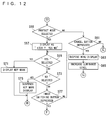
- the CPU 46 determines at a step S59 whether a protect mode has been selected or not. If “YES” here, that is, if the menu button 24 is depressed in a state shown in Figure 4(B), the CPU at a step S67 outputs letter data as shown in Figure 7(A). Subsequently, it is determined at a step S69 whether "YES” displayed on the LCD 14 is selected or not. If the determination here is "YES”, a key mark is displayed, at a step S71, at an upper right on the LCD 14 as shown in Figure 7(C) and protection is applied to the current reproduced image. Then, the process returns to the step S31.
- step S69 it is determined at a step S73 whether "NO” displayed on the LCD 14 has been selected or not. If “YES” is determined here, the key mark is suspended of display and the protection for the current reproduced image is cancelled. Thereafter, the process returns to the step S31. If “NO” is determined at the step S73, it is determined at a step S77 whether the image switching button 16 is operated or not. If “NO”, the process returns to the step S69. However, if "YES”, the process advances to a step S79. By the processes of the step S79 and the subsequent, an image is displayed on the LCD 14 in a procedure as shown in Figures 6(A) - (C).
- the CPU 46 determines at a step S61 whether the cancel button 26 is depressed or not. If “NO” here, the CPU 46 returns the process to the step S33. However, "YES”, the menu display is suspended at the step S63 and the luminance level is increased to the normal level at the step S65, returning the process to the step S23. Accordingly, if the cancel button 26 is depressed, a human figure image shown in Figure 5 only is displayed at the normal luminance level.
- the digital camera according to this invention is applicable not only to so-called digital still cameras for recording only still images but also to so-called video movies for recording motion images. Where this invention is applied to a video movie, it can be considered that reproduced images be reduced in luminance in response to menu operations during motion image reproduction.
- the switch SW1 was used to combine the character data with the image Y data. Alternatively, an adder may be employed in place of the switch SW1.
Landscapes
- Engineering & Computer Science (AREA)
- Human Computer Interaction (AREA)
- Multimedia (AREA)
- Signal Processing (AREA)
- General Engineering & Computer Science (AREA)
- Theoretical Computer Science (AREA)
- Physics & Mathematics (AREA)
- General Physics & Mathematics (AREA)
- Studio Devices (AREA)
- Television Signal Processing For Recording (AREA)
Applications Claiming Priority (3)
| Application Number | Priority Date | Filing Date | Title |
|---|---|---|---|
| JP269490/97 | 1997-10-02 | ||
| JP26949097 | 1997-10-02 | ||
| JP26949097A JP3599973B2 (ja) | 1997-10-02 | 1997-10-02 | ディジタルカメラ |
Publications (2)
| Publication Number | Publication Date |
|---|---|
| EP0907098A1 true EP0907098A1 (de) | 1999-04-07 |
| EP0907098B1 EP0907098B1 (de) | 2004-12-15 |
Family
ID=17473174
Family Applications (1)
| Application Number | Title | Priority Date | Filing Date |
|---|---|---|---|
| EP98118589A Expired - Lifetime EP0907098B1 (de) | 1997-10-02 | 1998-10-01 | Digitale Kamera mit einer Bild/Zeichen Überlagerungsanzeigefunktion |
Country Status (4)
| Country | Link |
|---|---|
| US (1) | US6683650B1 (de) |
| EP (1) | EP0907098B1 (de) |
| JP (1) | JP3599973B2 (de) |
| DE (1) | DE69828129T2 (de) |
Cited By (6)
| Publication number | Priority date | Publication date | Assignee | Title |
|---|---|---|---|---|
| GB2375678A (en) * | 2001-03-21 | 2002-11-20 | Hewlett Packard Co | Digital camera with function information display |
| EP1315369A1 (de) | 2001-10-29 | 2003-05-28 | Samsung Electronics Co., Ltd. | Benutzer-konfigurierbare elektronische Vorrichtung |
| WO2002086740A3 (en) * | 2001-04-18 | 2003-12-04 | Matsushita Electric Industrial Co Ltd | Portable terminal, overlay output method, and program therefor |
| US6856328B2 (en) * | 2000-10-31 | 2005-02-15 | Koninklijke Philips Electronics N.V. | System and method of displaying images |
| WO2005074268A1 (en) * | 2004-01-29 | 2005-08-11 | Koninklijke Philips Electronics, N.V. | On-screen control of a video playback device |
| US8072509B2 (en) | 2003-06-11 | 2011-12-06 | Nokia Corporation | Method and a system for image processing, a device, and an image record |
Families Citing this family (15)
| Publication number | Priority date | Publication date | Assignee | Title |
|---|---|---|---|---|
| US6864917B2 (en) * | 2001-09-04 | 2005-03-08 | Eastman Kodak Company | Hybrid film-electronic camera having a dynamic number of stored electronic images protected from overwriting and method |
| US7015957B2 (en) * | 2001-09-04 | 2006-03-21 | Eastman Kodak Company | Camera that downloads electronic images having metadata identifying images previously excluded from first in-first out overwriting and method |
| US20030043282A1 (en) * | 2001-09-04 | 2003-03-06 | Eastman Kodak Company | Camera having selective image exclusion from first in-first out electronic image overwriting and method |
| CN100556109C (zh) | 2002-01-11 | 2009-10-28 | 株式会社尼康 | 数码相机 |
| CN100438603C (zh) * | 2002-01-31 | 2008-11-26 | 株式会社尼康 | 数码相机 |
| AU2003211441A1 (en) | 2002-02-18 | 2003-09-04 | Nikon Corporation | Digital camera |
| JP4006347B2 (ja) * | 2002-03-15 | 2007-11-14 | キヤノン株式会社 | 画像処理装置、画像処理システム、画像処理方法、記憶媒体、及びプログラム |
| JP4186878B2 (ja) * | 2004-06-08 | 2008-11-26 | ソニー株式会社 | 動画像再生装置,動画像再生方法,プログラム及びその記録媒体 |
| KR101120027B1 (ko) * | 2004-11-01 | 2012-03-23 | 삼성전자주식회사 | 셔터 반누름 시에 osd 처리 장치 및 방법 |
| JP2007180641A (ja) * | 2005-12-27 | 2007-07-12 | Sony Corp | 撮像装置及び撮像装置の表示方法 |
| JP4709657B2 (ja) * | 2006-02-20 | 2011-06-22 | 株式会社東芝 | 放送記録装置及び放送記録方法 |
| US20080055453A1 (en) * | 2006-09-05 | 2008-03-06 | Battles Amy E | Displaying a live view and captured images in a digital camera |
| USD738400S1 (en) * | 2013-02-22 | 2015-09-08 | Samsung Electronics Co., Ltd. | Display screen portion with icon |
| USD725145S1 (en) * | 2013-05-28 | 2015-03-24 | Deere & Company | Display screen with icon |
| CN104320583B (zh) * | 2014-11-03 | 2018-12-14 | 联想(北京)有限公司 | 图像处理方法、图像处理装置及电子设备 |
Citations (3)
| Publication number | Priority date | Publication date | Assignee | Title |
|---|---|---|---|---|
| JPH05336484A (ja) * | 1992-05-29 | 1993-12-17 | Konica Corp | スチルビデオカメラ |
| JPH08181915A (ja) * | 1994-12-22 | 1996-07-12 | Kyocera Corp | スーパーインポーズ表示装置 |
| US5559554A (en) * | 1993-12-01 | 1996-09-24 | Sharp Kabushiki Kaisha | Monitor screen-integrated video camera |
Family Cites Families (24)
| Publication number | Priority date | Publication date | Assignee | Title |
|---|---|---|---|---|
| JPS5841793B2 (ja) | 1981-04-22 | 1983-09-14 | 工業技術院長 | レ−ザ共振器破壊検知装置 |
| JPS6377276A (ja) | 1986-09-19 | 1988-04-07 | Matsushita Electric Ind Co Ltd | 液晶表示装置 |
| JP2691050B2 (ja) | 1990-05-24 | 1997-12-17 | 富士写真フイルム株式会社 | ハイブリッドファインダ |
| JP3329391B2 (ja) * | 1991-01-22 | 2002-09-30 | ソニー株式会社 | 文字入力装置および方法 |
| JPH04282973A (ja) * | 1991-03-12 | 1992-10-08 | Canon Inc | 切り換え装置およびビデオカメラ |
| JPH0619444A (ja) | 1992-07-02 | 1994-01-28 | Hitachi Ltd | 情報処理装置 |
| JP3298176B2 (ja) | 1992-09-24 | 2002-07-02 | ソニー株式会社 | カメラ装置 |
| US5386247A (en) * | 1993-06-02 | 1995-01-31 | Thomson Consumer Electronics, Inc. | Video display having progressively dimmed video images and constant brightness auxiliary images |
| EP0702878A4 (de) * | 1993-06-07 | 1997-01-02 | Scientific Atlanta | Anzeigesystem für ein abonnentenendgerät |
| JPH07274049A (ja) * | 1994-03-30 | 1995-10-20 | Sony Corp | 機能情報用メモリを備えた電子機器 |
| US5502504A (en) * | 1994-04-28 | 1996-03-26 | Prevue Networks, Inc. | Video mix program guide |
| KR970007479B1 (ko) * | 1994-06-09 | 1997-05-09 | 삼성전자 주식회사 | 온 스크린 디스플레이 신호를 이용한 배경화면 보상회로 |
| JPH086550A (ja) | 1994-06-16 | 1996-01-12 | Kawai Musical Instr Mfg Co Ltd | 電子楽器およびその周辺装置の表示装置 |
| JPH0886996A (ja) | 1994-09-16 | 1996-04-02 | Canon Inc | 液晶表示装置 |
| US5652930A (en) * | 1994-12-16 | 1997-07-29 | Eastman Kodak Company | Camera information display |
| JPH08205014A (ja) | 1995-01-31 | 1996-08-09 | Casio Comput Co Ltd | 電子スチルカメラ |
| JP3572595B2 (ja) * | 1995-07-21 | 2004-10-06 | ソニー株式会社 | 電子番組ガイド表示制御装置および方法 |
| JP3037140B2 (ja) * | 1996-06-13 | 2000-04-24 | 日本電気オフィスシステム株式会社 | デジタルカメラ |
| US6055381A (en) * | 1996-11-21 | 2000-04-25 | Olympus Optical Co., Ltd. | Silver film camera capable of displaying an electronically picked-up image |
| US6342900B1 (en) * | 1996-12-06 | 2002-01-29 | Nikon Corporation | Information processing apparatus |
| US5845166A (en) * | 1997-02-20 | 1998-12-01 | Eastman Kodak Company | Hybrid camera with identification matching of film and electronic images |
| US6118480A (en) * | 1997-05-05 | 2000-09-12 | Flashpoint Technology, Inc. | Method and apparatus for integrating a digital camera user interface across multiple operating modes |
| US6111614A (en) * | 1997-10-17 | 2000-08-29 | Sony Corporation | Method and apparatus for displaying an electronic menu having components with differing levels of transparency |
| US6133962A (en) * | 1998-10-30 | 2000-10-17 | Sony Corporation | Electronic program guide having different modes for viewing |
-
1997
- 1997-10-02 JP JP26949097A patent/JP3599973B2/ja not_active Expired - Fee Related
-
1998
- 1998-09-30 US US09/162,772 patent/US6683650B1/en not_active Expired - Fee Related
- 1998-10-01 DE DE69828129T patent/DE69828129T2/de not_active Expired - Fee Related
- 1998-10-01 EP EP98118589A patent/EP0907098B1/de not_active Expired - Lifetime
Patent Citations (3)
| Publication number | Priority date | Publication date | Assignee | Title |
|---|---|---|---|---|
| JPH05336484A (ja) * | 1992-05-29 | 1993-12-17 | Konica Corp | スチルビデオカメラ |
| US5559554A (en) * | 1993-12-01 | 1996-09-24 | Sharp Kabushiki Kaisha | Monitor screen-integrated video camera |
| JPH08181915A (ja) * | 1994-12-22 | 1996-07-12 | Kyocera Corp | スーパーインポーズ表示装置 |
Non-Patent Citations (4)
| Title |
|---|
| DATABASE WPI Section EI Week 9404, Derwent World Patents Index; Class W04, AN 94-030522, XP002087285 * |
| DATABASE WPI Section EI Week 9638, Derwent World Patents Index; Class W04, AN 96-377609, XP002087284 * |
| PATENT ABSTRACTS OF JAPAN vol. 18, no. 165 (E - 1527) 18 March 1994 (1994-03-18) * |
| PATENT ABSTRACTS OF JAPAN vol. 96, no. 11 29 November 1996 (1996-11-29) * |
Cited By (7)
| Publication number | Priority date | Publication date | Assignee | Title |
|---|---|---|---|---|
| US6856328B2 (en) * | 2000-10-31 | 2005-02-15 | Koninklijke Philips Electronics N.V. | System and method of displaying images |
| GB2375678A (en) * | 2001-03-21 | 2002-11-20 | Hewlett Packard Co | Digital camera with function information display |
| WO2002086740A3 (en) * | 2001-04-18 | 2003-12-04 | Matsushita Electric Industrial Co Ltd | Portable terminal, overlay output method, and program therefor |
| US7193635B2 (en) | 2001-04-18 | 2007-03-20 | Matsushita Electric Industrial Co., Ltd. | Portable terminal, overlay output method, and program therefor |
| EP1315369A1 (de) | 2001-10-29 | 2003-05-28 | Samsung Electronics Co., Ltd. | Benutzer-konfigurierbare elektronische Vorrichtung |
| US8072509B2 (en) | 2003-06-11 | 2011-12-06 | Nokia Corporation | Method and a system for image processing, a device, and an image record |
| WO2005074268A1 (en) * | 2004-01-29 | 2005-08-11 | Koninklijke Philips Electronics, N.V. | On-screen control of a video playback device |
Also Published As
| Publication number | Publication date |
|---|---|
| DE69828129D1 (de) | 2005-01-20 |
| JP3599973B2 (ja) | 2004-12-08 |
| DE69828129T2 (de) | 2005-11-03 |
| EP0907098B1 (de) | 2004-12-15 |
| US6683650B1 (en) | 2004-01-27 |
| JPH11112839A (ja) | 1999-04-23 |
Similar Documents
| Publication | Publication Date | Title |
|---|---|---|
| EP0907098B1 (de) | Digitale Kamera mit einer Bild/Zeichen Überlagerungsanzeigefunktion | |
| US9116610B2 (en) | Imaging apparatus and user interface | |
| EP0944248B1 (de) | Digitale Kamera mit Möglichkeit zur Bildbearbeitung | |
| US6188432B1 (en) | Information processing method and apparatus for displaying and zooming an object image and a line drawing | |
| US9451169B2 (en) | Imaging apparatus and capture assist mark usage control method | |
| US9065986B2 (en) | Imaging apparatus and imaging system | |
| JPH10240436A (ja) | 情報処理装置および記録媒体 | |
| JP2005341416A (ja) | 撮像機能付き電子機器およびその画像表示方法 | |
| JPH08205014A (ja) | 電子スチルカメラ | |
| JPH08223525A (ja) | 画像記憶装置の表示制御方法および該表示制御方法が適用される電子スチルカメラ | |
| US20010043278A1 (en) | Information input apparatus | |
| JP3867181B2 (ja) | デジタルスチルカメラおよび画像転送方法 | |
| JP2007199311A (ja) | 画像表示装置及び撮像装置 | |
| US7408580B2 (en) | Image display apparatus, image display method and computer program | |
| JP4235130B2 (ja) | デジタルカメラ | |
| JPH11187351A (ja) | 撮像装置及びその制御方法 | |
| JPH1056610A (ja) | 電子撮像装置 | |
| JPH10341361A (ja) | パノラマ画像撮影機能付デジタルカメラ | |
| JP3757469B2 (ja) | 印刷装置および印刷方法 | |
| JP3729200B2 (ja) | デジタルカメラ | |
| JPH10243353A (ja) | 画像表示装置、画像処理システム、画像処理方法、及び記憶媒体 | |
| JP2000333044A (ja) | 表示操作装置及び設定状態表示方法 | |
| JP2002290813A (ja) | ホワイトバランス設定方法 | |
| US20070100889A1 (en) | Information processing device, an information processing method, and an information processing program | |
| JPH06237407A (ja) | ビデオカメラ |
Legal Events
| Date | Code | Title | Description |
|---|---|---|---|
| PUAI | Public reference made under article 153(3) epc to a published international application that has entered the european phase |
Free format text: ORIGINAL CODE: 0009012 |
|
| AK | Designated contracting states |
Kind code of ref document: A1 Designated state(s): DE FR GB |
|
| AX | Request for extension of the european patent |
Free format text: AL;LT;LV;MK;RO;SI |
|
| 17P | Request for examination filed |
Effective date: 19990322 |
|
| AKX | Designation fees paid |
Free format text: DE FR GB |
|
| 17Q | First examination report despatched |
Effective date: 20030401 |
|
| GRAP | Despatch of communication of intention to grant a patent |
Free format text: ORIGINAL CODE: EPIDOSNIGR1 |
|
| GRAS | Grant fee paid |
Free format text: ORIGINAL CODE: EPIDOSNIGR3 |
|
| GRAA | (expected) grant |
Free format text: ORIGINAL CODE: 0009210 |
|
| AK | Designated contracting states |
Kind code of ref document: B1 Designated state(s): DE FR GB |
|
| PG25 | Lapsed in a contracting state [announced via postgrant information from national office to epo] |
Ref country code: FR Free format text: LAPSE BECAUSE OF FAILURE TO SUBMIT A TRANSLATION OF THE DESCRIPTION OR TO PAY THE FEE WITHIN THE PRESCRIBED TIME-LIMIT Effective date: 20041215 |
|
| REG | Reference to a national code |
Ref country code: GB Ref legal event code: FG4D |
|
| REF | Corresponds to: |
Ref document number: 69828129 Country of ref document: DE Date of ref document: 20050120 Kind code of ref document: P Owner name: ANTILA, MATTI |
|
| PLBE | No opposition filed within time limit |
Free format text: ORIGINAL CODE: 0009261 |
|
| STAA | Information on the status of an ep patent application or granted ep patent |
Free format text: STATUS: NO OPPOSITION FILED WITHIN TIME LIMIT |
|
| 26N | No opposition filed |
Effective date: 20050916 |
|
| EN | Fr: translation not filed | ||
| PGFP | Annual fee paid to national office [announced via postgrant information from national office to epo] |
Ref country code: DE Payment date: 20081014 Year of fee payment: 11 |
|
| PGFP | Annual fee paid to national office [announced via postgrant information from national office to epo] |
Ref country code: GB Payment date: 20081001 Year of fee payment: 11 |
|
| PG25 | Lapsed in a contracting state [announced via postgrant information from national office to epo] |
Ref country code: DE Free format text: LAPSE BECAUSE OF NON-PAYMENT OF DUE FEES Effective date: 20100501 |
|
| PG25 | Lapsed in a contracting state [announced via postgrant information from national office to epo] |
Ref country code: GB Free format text: LAPSE BECAUSE OF NON-PAYMENT OF DUE FEES Effective date: 20091001 |