EP0907191A2 - Condensateur électrolytique - Google Patents
Condensateur électrolytique Download PDFInfo
- Publication number
- EP0907191A2 EP0907191A2 EP98114982A EP98114982A EP0907191A2 EP 0907191 A2 EP0907191 A2 EP 0907191A2 EP 98114982 A EP98114982 A EP 98114982A EP 98114982 A EP98114982 A EP 98114982A EP 0907191 A2 EP0907191 A2 EP 0907191A2
- Authority
- EP
- European Patent Office
- Prior art keywords
- electrolytic
- electrolytic capacitor
- separator
- electrolytic solution
- capacitor
- Prior art date
- Legal status (The legal status is an assumption and is not a legal conclusion. Google has not performed a legal analysis and makes no representation as to the accuracy of the status listed.)
- Granted
Links
- 239000003990 capacitor Substances 0.000 title claims abstract description 397
- 239000008151 electrolyte solution Substances 0.000 claims abstract description 183
- 239000004372 Polyvinyl alcohol Substances 0.000 claims abstract description 163
- 229920002451 polyvinyl alcohol Polymers 0.000 claims abstract description 163
- LYCAIKOWRPUZTN-UHFFFAOYSA-N Ethylene glycol Chemical compound OCCO LYCAIKOWRPUZTN-UHFFFAOYSA-N 0.000 claims abstract description 129
- 239000011888 foil Substances 0.000 claims abstract description 99
- KGBXLFKZBHKPEV-UHFFFAOYSA-N boric acid Chemical compound OB(O)O KGBXLFKZBHKPEV-UHFFFAOYSA-N 0.000 claims abstract description 78
- 239000004327 boric acid Substances 0.000 claims abstract description 78
- 239000000835 fiber Substances 0.000 claims abstract description 54
- 238000000034 method Methods 0.000 claims abstract description 20
- 239000000243 solution Substances 0.000 claims abstract description 18
- 238000007789 sealing Methods 0.000 claims abstract description 15
- 238000004804 winding Methods 0.000 claims abstract description 13
- 230000008569 process Effects 0.000 claims abstract description 12
- 238000002156 mixing Methods 0.000 claims abstract description 6
- 238000007127 saponification reaction Methods 0.000 claims description 32
- -1 aliphatic saturated dicarboxylic acid Chemical class 0.000 claims description 23
- OFOBLEOULBTSOW-UHFFFAOYSA-N Malonic acid Chemical compound OC(=O)CC(O)=O OFOBLEOULBTSOW-UHFFFAOYSA-N 0.000 claims description 16
- 150000003839 salts Chemical class 0.000 claims description 16
- 229910052782 aluminium Inorganic materials 0.000 description 91
- XAGFODPZIPBFFR-UHFFFAOYSA-N aluminium Chemical compound [Al] XAGFODPZIPBFFR-UHFFFAOYSA-N 0.000 description 91
- 230000000052 comparative effect Effects 0.000 description 81
- 239000000123 paper Substances 0.000 description 36
- 238000010438 heat treatment Methods 0.000 description 21
- 150000001991 dicarboxylic acids Chemical class 0.000 description 15
- 239000002655 kraft paper Substances 0.000 description 13
- 229910052751 metal Inorganic materials 0.000 description 13
- 239000002184 metal Substances 0.000 description 13
- 239000007864 aqueous solution Substances 0.000 description 12
- SPZBYSKKSSLUKN-UHFFFAOYSA-N diazanium;2-butyloctanedioate Chemical compound [NH4+].[NH4+].CCCCC(C([O-])=O)CCCCCC([O-])=O SPZBYSKKSSLUKN-UHFFFAOYSA-N 0.000 description 12
- 230000000977 initiatory effect Effects 0.000 description 11
- LXEKPEMOWBOYRF-UHFFFAOYSA-N [2-[(1-azaniumyl-1-imino-2-methylpropan-2-yl)diazenyl]-2-methylpropanimidoyl]azanium;dichloride Chemical compound Cl.Cl.NC(=N)C(C)(C)N=NC(C)(C)C(N)=N LXEKPEMOWBOYRF-UHFFFAOYSA-N 0.000 description 10
- 230000008859 change Effects 0.000 description 10
- 238000006116 polymerization reaction Methods 0.000 description 10
- FOFMIZPXOAUNDQ-UHFFFAOYSA-N azane;2-methylnonanedioic acid Chemical compound N.N.OC(=O)C(C)CCCCCCC(O)=O FOFMIZPXOAUNDQ-UHFFFAOYSA-N 0.000 description 9
- 230000002195 synergetic effect Effects 0.000 description 9
- 150000001875 compounds Chemical class 0.000 description 8
- 244000025254 Cannabis sativa Species 0.000 description 7
- 235000012766 Cannabis sativa ssp. sativa var. sativa Nutrition 0.000 description 7
- 235000012765 Cannabis sativa ssp. sativa var. spontanea Nutrition 0.000 description 7
- 235000009120 camo Nutrition 0.000 description 7
- 235000005607 chanvre indien Nutrition 0.000 description 7
- 229920001971 elastomer Polymers 0.000 description 7
- 239000011487 hemp Substances 0.000 description 7
- OWCLRJQYKBAMOL-UHFFFAOYSA-N 2-butyloctanedioic acid Chemical compound CCCCC(C(O)=O)CCCCCC(O)=O OWCLRJQYKBAMOL-UHFFFAOYSA-N 0.000 description 6
- 229920002978 Vinylon Polymers 0.000 description 6
- 239000002253 acid Substances 0.000 description 6
- 125000001931 aliphatic group Chemical group 0.000 description 6
- 230000006872 improvement Effects 0.000 description 6
- 239000000203 mixture Substances 0.000 description 6
- FLDCSPABIQBYKP-UHFFFAOYSA-N 5-chloro-1,2-dimethylbenzimidazole Chemical compound ClC1=CC=C2N(C)C(C)=NC2=C1 FLDCSPABIQBYKP-UHFFFAOYSA-N 0.000 description 5
- 239000001741 Ammonium adipate Substances 0.000 description 5
- LFQSCWFLJHTTHZ-UHFFFAOYSA-N Ethanol Chemical compound CCO LFQSCWFLJHTTHZ-UHFFFAOYSA-N 0.000 description 5
- 235000019293 ammonium adipate Nutrition 0.000 description 5
- 239000003792 electrolyte Substances 0.000 description 5
- RAXXELZNTBOGNW-UHFFFAOYSA-N imidazole Natural products C1=CNC=N1 RAXXELZNTBOGNW-UHFFFAOYSA-N 0.000 description 5
- 239000000843 powder Substances 0.000 description 5
- 238000009987 spinning Methods 0.000 description 5
- PEDCQBHIVMGVHV-UHFFFAOYSA-N Glycerine Chemical compound OCC(O)CO PEDCQBHIVMGVHV-UHFFFAOYSA-N 0.000 description 4
- NBIIXXVUZAFLBC-UHFFFAOYSA-N Phosphoric acid Chemical compound OP(O)(O)=O NBIIXXVUZAFLBC-UHFFFAOYSA-N 0.000 description 4
- 150000007513 acids Chemical class 0.000 description 4
- 239000011248 coating agent Substances 0.000 description 4
- 238000000576 coating method Methods 0.000 description 4
- 230000018044 dehydration Effects 0.000 description 4
- 238000006297 dehydration reaction Methods 0.000 description 4
- 238000000578 dry spinning Methods 0.000 description 4
- 238000010410 dusting Methods 0.000 description 4
- 239000007789 gas Substances 0.000 description 4
- 238000001879 gelation Methods 0.000 description 4
- BDJRBEYXGGNYIS-UHFFFAOYSA-N nonanedioic acid Chemical compound OC(=O)CCCCCCCC(O)=O BDJRBEYXGGNYIS-UHFFFAOYSA-N 0.000 description 4
- 238000002360 preparation method Methods 0.000 description 4
- CXMXRPHRNRROMY-UHFFFAOYSA-N sebacic acid Chemical compound OC(=O)CCCCCCCCC(O)=O CXMXRPHRNRROMY-UHFFFAOYSA-N 0.000 description 4
- KWIPUXXIFQQMKN-UHFFFAOYSA-N 2-azaniumyl-3-(4-cyanophenyl)propanoate Chemical compound OC(=O)C(N)CC1=CC=C(C#N)C=C1 KWIPUXXIFQQMKN-UHFFFAOYSA-N 0.000 description 3
- WEVYAHXRMPXWCK-UHFFFAOYSA-N Acetonitrile Chemical compound CC#N WEVYAHXRMPXWCK-UHFFFAOYSA-N 0.000 description 3
- WVDDGKGOMKODPV-UHFFFAOYSA-N Benzyl alcohol Chemical compound OCC1=CC=CC=C1 WVDDGKGOMKODPV-UHFFFAOYSA-N 0.000 description 3
- ZMXDDKWLCZADIW-UHFFFAOYSA-N N,N-Dimethylformamide Chemical compound CN(C)C=O ZMXDDKWLCZADIW-UHFFFAOYSA-N 0.000 description 3
- DNIAPMSPPWPWGF-UHFFFAOYSA-N Propylene glycol Chemical compound CC(O)CO DNIAPMSPPWPWGF-UHFFFAOYSA-N 0.000 description 3
- ZMANZCXQSJIPKH-UHFFFAOYSA-N Triethylamine Chemical compound CCN(CC)CC ZMANZCXQSJIPKH-UHFFFAOYSA-N 0.000 description 3
- 229940090948 ammonium benzoate Drugs 0.000 description 3
- 239000003989 dielectric material Substances 0.000 description 3
- 230000000694 effects Effects 0.000 description 3
- 238000005530 etching Methods 0.000 description 3
- 239000002904 solvent Substances 0.000 description 3
- XWVFEDFALKHCLK-UHFFFAOYSA-N 2-methylnonanedioic acid Chemical compound OC(=O)C(C)CCCCCCC(O)=O XWVFEDFALKHCLK-UHFFFAOYSA-N 0.000 description 2
- YEJRWHAVMIAJKC-UHFFFAOYSA-N 4-Butyrolactone Chemical compound O=C1CCCO1 YEJRWHAVMIAJKC-UHFFFAOYSA-N 0.000 description 2
- OZJPLYNZGCXSJM-UHFFFAOYSA-N 5-valerolactone Chemical compound O=C1CCCCO1 OZJPLYNZGCXSJM-UHFFFAOYSA-N 0.000 description 2
- ROSDSFDQCJNGOL-UHFFFAOYSA-N Dimethylamine Chemical compound CNC ROSDSFDQCJNGOL-UHFFFAOYSA-N 0.000 description 2
- IAZDPXIOMUYVGZ-UHFFFAOYSA-N Dimethylsulphoxide Chemical compound CS(C)=O IAZDPXIOMUYVGZ-UHFFFAOYSA-N 0.000 description 2
- QUSNBJAOOMFDIB-UHFFFAOYSA-N Ethylamine Chemical compound CCN QUSNBJAOOMFDIB-UHFFFAOYSA-N 0.000 description 2
- BAVYZALUXZFZLV-UHFFFAOYSA-N Methylamine Chemical compound NC BAVYZALUXZFZLV-UHFFFAOYSA-N 0.000 description 2
- 240000000907 Musa textilis Species 0.000 description 2
- LRHPLDYGYMQRHN-UHFFFAOYSA-N N-Butanol Chemical compound CCCCO LRHPLDYGYMQRHN-UHFFFAOYSA-N 0.000 description 2
- SECXISVLQFMRJM-UHFFFAOYSA-N N-Methylpyrrolidone Chemical compound CN1CCCC1=O SECXISVLQFMRJM-UHFFFAOYSA-N 0.000 description 2
- AMQJEAYHLZJPGS-UHFFFAOYSA-N N-Pentanol Chemical compound CCCCCO AMQJEAYHLZJPGS-UHFFFAOYSA-N 0.000 description 2
- PMDCZENCAXMSOU-UHFFFAOYSA-N N-ethylacetamide Chemical compound CCNC(C)=O PMDCZENCAXMSOU-UHFFFAOYSA-N 0.000 description 2
- ATHHXGZTWNVVOU-UHFFFAOYSA-N N-methylformamide Chemical compound CNC=O ATHHXGZTWNVVOU-UHFFFAOYSA-N 0.000 description 2
- PMZURENOXWZQFD-UHFFFAOYSA-L Sodium Sulfate Chemical compound [Na+].[Na+].[O-]S([O-])(=O)=O PMZURENOXWZQFD-UHFFFAOYSA-L 0.000 description 2
- 239000003929 acidic solution Substances 0.000 description 2
- 239000000654 additive Substances 0.000 description 2
- WNLRTRBMVRJNCN-UHFFFAOYSA-N adipic acid Chemical compound OC(=O)CCCCC(O)=O WNLRTRBMVRJNCN-UHFFFAOYSA-N 0.000 description 2
- 229910000147 aluminium phosphate Inorganic materials 0.000 description 2
- 150000001408 amides Chemical class 0.000 description 2
- 150000001412 amines Chemical class 0.000 description 2
- WPYMKLBDIGXBTP-UHFFFAOYSA-N benzoic acid Chemical compound OC(=O)C1=CC=CC=C1 WPYMKLBDIGXBTP-UHFFFAOYSA-N 0.000 description 2
- 230000015572 biosynthetic process Effects 0.000 description 2
- HQABUPZFAYXKJW-UHFFFAOYSA-N butan-1-amine Chemical compound CCCCN HQABUPZFAYXKJW-UHFFFAOYSA-N 0.000 description 2
- 125000004432 carbon atom Chemical group C* 0.000 description 2
- 150000001768 cations Chemical class 0.000 description 2
- DMBHHRLKUKUOEG-UHFFFAOYSA-N diphenylamine Chemical compound C=1C=CC=CC=1NC1=CC=CC=C1 DMBHHRLKUKUOEG-UHFFFAOYSA-N 0.000 description 2
- TVIDDXQYHWJXFK-UHFFFAOYSA-N dodecanedioic acid Chemical compound OC(=O)CCCCCCCCCCC(O)=O TVIDDXQYHWJXFK-UHFFFAOYSA-N 0.000 description 2
- LIWAQLJGPBVORC-UHFFFAOYSA-N ethylmethylamine Chemical compound CCNC LIWAQLJGPBVORC-UHFFFAOYSA-N 0.000 description 2
- GAEKPEKOJKCEMS-UHFFFAOYSA-N gamma-valerolactone Chemical compound CC1CCC(=O)O1 GAEKPEKOJKCEMS-UHFFFAOYSA-N 0.000 description 2
- 235000011187 glycerol Nutrition 0.000 description 2
- 230000020169 heat generation Effects 0.000 description 2
- ZSIAUFGUXNUGDI-UHFFFAOYSA-N hexan-1-ol Chemical compound CCCCCCO ZSIAUFGUXNUGDI-UHFFFAOYSA-N 0.000 description 2
- 239000011261 inert gas Substances 0.000 description 2
- 238000004519 manufacturing process Methods 0.000 description 2
- 230000007246 mechanism Effects 0.000 description 2
- WLJVNTCWHIRURA-UHFFFAOYSA-N pimelic acid Chemical compound OC(=O)CCCCCC(O)=O WLJVNTCWHIRURA-UHFFFAOYSA-N 0.000 description 2
- 239000002798 polar solvent Substances 0.000 description 2
- WGYKZJWCGVVSQN-UHFFFAOYSA-N propylamine Chemical compound CCCN WGYKZJWCGVVSQN-UHFFFAOYSA-N 0.000 description 2
- 150000003242 quaternary ammonium salts Chemical class 0.000 description 2
- 239000003566 sealing material Substances 0.000 description 2
- 229910052938 sodium sulfate Inorganic materials 0.000 description 2
- 235000011152 sodium sulphate Nutrition 0.000 description 2
- 239000007858 starting material Substances 0.000 description 2
- TYFQFVWCELRYAO-UHFFFAOYSA-N suberic acid Chemical compound OC(=O)CCCCCCC(O)=O TYFQFVWCELRYAO-UHFFFAOYSA-N 0.000 description 2
- GETQZCLCWQTVFV-UHFFFAOYSA-N trimethylamine Chemical compound CN(C)C GETQZCLCWQTVFV-UHFFFAOYSA-N 0.000 description 2
- 238000002166 wet spinning Methods 0.000 description 2
- XLSXKCPCBOMHON-UHFFFAOYSA-N 1,1-dimethoxypropan-1-ol Chemical compound CCC(O)(OC)OC XLSXKCPCBOMHON-UHFFFAOYSA-N 0.000 description 1
- HJSYENHCQNNLAS-UHFFFAOYSA-N 1,2,4-trimethyl-4,5-dihydroimidazole Chemical compound CC1CN(C)C(C)=N1 HJSYENHCQNNLAS-UHFFFAOYSA-N 0.000 description 1
- QEIHVTKMBYEXPZ-UHFFFAOYSA-N 1,2-dimethyl-4,5-dihydroimidazole Chemical compound CN1CCN=C1C QEIHVTKMBYEXPZ-UHFFFAOYSA-N 0.000 description 1
- ZFDWWDZLRKHULH-UHFFFAOYSA-N 1,2-dimethyl-5,6-dihydro-4h-pyrimidine Chemical compound CN1CCCN=C1C ZFDWWDZLRKHULH-UHFFFAOYSA-N 0.000 description 1
- GIWQSPITLQVMSG-UHFFFAOYSA-N 1,2-dimethylimidazole Chemical compound CC1=NC=CN1C GIWQSPITLQVMSG-UHFFFAOYSA-N 0.000 description 1
- CYSGHNMQYZDMIA-UHFFFAOYSA-N 1,3-Dimethyl-2-imidazolidinon Chemical compound CN1CCN(C)C1=O CYSGHNMQYZDMIA-UHFFFAOYSA-N 0.000 description 1
- NYCCIHSMVNRABA-UHFFFAOYSA-N 1,3-diethylimidazolidin-2-one Chemical compound CCN1CCN(CC)C1=O NYCCIHSMVNRABA-UHFFFAOYSA-N 0.000 description 1
- NFJSYLMJBNUDNG-UHFFFAOYSA-N 1,3-dipropylimidazolidin-2-one Chemical compound CCCN1CCN(CCC)C1=O NFJSYLMJBNUDNG-UHFFFAOYSA-N 0.000 description 1
- OEYNWAWWSZUGDU-UHFFFAOYSA-N 1-methoxypropane-1,2-diol Chemical compound COC(O)C(C)O OEYNWAWWSZUGDU-UHFFFAOYSA-N 0.000 description 1
- MCTWTZJPVLRJOU-UHFFFAOYSA-N 1-methyl-1H-imidazole Chemical compound CN1C=CN=C1 MCTWTZJPVLRJOU-UHFFFAOYSA-N 0.000 description 1
- VWUDGSYCJGEGOI-UHFFFAOYSA-N 1-methyl-2-phenyl-4,5-dihydroimidazole Chemical compound CN1CCN=C1C1=CC=CC=C1 VWUDGSYCJGEGOI-UHFFFAOYSA-N 0.000 description 1
- ANFXTILBDGTSEG-UHFFFAOYSA-N 1-methyl-4,5-dihydroimidazole Chemical compound CN1CCN=C1 ANFXTILBDGTSEG-UHFFFAOYSA-N 0.000 description 1
- ABNDDOBSIHWESM-UHFFFAOYSA-N 1-methyl-5,6-dihydro-4h-pyrimidine Chemical compound CN1CCCN=C1 ABNDDOBSIHWESM-UHFFFAOYSA-N 0.000 description 1
- FGYADSCZTQOAFK-UHFFFAOYSA-N 1-methylbenzimidazole Chemical compound C1=CC=C2N(C)C=NC2=C1 FGYADSCZTQOAFK-UHFFFAOYSA-N 0.000 description 1
- SEULWJSKCVACTH-UHFFFAOYSA-N 1-phenylimidazole Chemical compound C1=NC=CN1C1=CC=CC=C1 SEULWJSKCVACTH-UHFFFAOYSA-N 0.000 description 1
- HYZJCKYKOHLVJF-UHFFFAOYSA-N 1H-benzimidazole Chemical compound C1=CC=C2NC=NC2=C1 HYZJCKYKOHLVJF-UHFFFAOYSA-N 0.000 description 1
- BQNDPALRJDCXOY-UHFFFAOYSA-N 2,3-dibutylbutanedioic acid Chemical compound CCCCC(C(O)=O)C(C(O)=O)CCCC BQNDPALRJDCXOY-UHFFFAOYSA-N 0.000 description 1
- HVTQDSGGHBWVTR-UHFFFAOYSA-N 2-[4-[2-(2,3-dihydro-1H-inden-2-ylamino)pyrimidin-5-yl]-3-phenylmethoxypyrazol-1-yl]-1-morpholin-4-ylethanone Chemical compound C(C1=CC=CC=C1)OC1=NN(C=C1C=1C=NC(=NC=1)NC1CC2=CC=CC=C2C1)CC(=O)N1CCOCC1 HVTQDSGGHBWVTR-UHFFFAOYSA-N 0.000 description 1
- BAXXIBXLWXEPGF-UHFFFAOYSA-N 2-benzyl-1-methylbenzimidazole Chemical compound N=1C2=CC=CC=C2N(C)C=1CC1=CC=CC=C1 BAXXIBXLWXEPGF-UHFFFAOYSA-N 0.000 description 1
- ZNQVEEAIQZEUHB-UHFFFAOYSA-N 2-ethoxyethanol Chemical compound CCOCCO ZNQVEEAIQZEUHB-UHFFFAOYSA-N 0.000 description 1
- LRZVCQMHMOPSLT-UHFFFAOYSA-N 2-ethyl-1,4-dimethyl-4,5-dihydroimidazole Chemical compound CCC1=NC(C)CN1C LRZVCQMHMOPSLT-UHFFFAOYSA-N 0.000 description 1
- GVQDVIAKPKRTFJ-UHFFFAOYSA-N 2-ethyl-1,4-dimethylimidazole Chemical compound CCC1=NC(C)=CN1C GVQDVIAKPKRTFJ-UHFFFAOYSA-N 0.000 description 1
- QKHDBGZCZSBZFR-UHFFFAOYSA-N 2-methyl-3-(4-methylpentan-2-yl)-2-pentan-2-ylbutanedioic acid Chemical compound CCCC(C)C(C)(C(O)=O)C(C(O)=O)C(C)CC(C)C QKHDBGZCZSBZFR-UHFFFAOYSA-N 0.000 description 1
- YTWKEZPKELNCRE-UHFFFAOYSA-N 3,5,7,8-tetramethyldodecanedioic acid Chemical compound OC(=O)CC(C)CC(C)CC(C)C(C)CCCC(O)=O YTWKEZPKELNCRE-UHFFFAOYSA-N 0.000 description 1
- FCEUHAMMXRPAQH-UHFFFAOYSA-N 4,6-bis(methoxycarbonyl)-2,4,6-trimethyltridecanedioic acid Chemical compound OC(=O)C(C)CC(C)(C(=O)OC)CC(C)(C(=O)OC)CCCCCCC(O)=O FCEUHAMMXRPAQH-UHFFFAOYSA-N 0.000 description 1
- OOAUQCVBVWVNHC-UHFFFAOYSA-N 4,6-dimethyl-2-(4-methylpentan-2-yl)octanedioic acid Chemical compound CC(C)CC(C)C(C(O)=O)CC(C)CC(C)CC(O)=O OOAUQCVBVWVNHC-UHFFFAOYSA-N 0.000 description 1
- WWFMNQCTFZQFCL-UHFFFAOYSA-N 4-methoxycarbonyl-2,4-dimethylundecanedioic acid Chemical compound OC(=O)C(C)CC(C)(C(=O)OC)CCCCCCC(O)=O WWFMNQCTFZQFCL-UHFFFAOYSA-N 0.000 description 1
- OTLNPYWUJOZPPA-UHFFFAOYSA-N 4-nitrobenzoic acid Chemical compound OC(=O)C1=CC=C([N+]([O-])=O)C=C1 OTLNPYWUJOZPPA-UHFFFAOYSA-N 0.000 description 1
- BTJIUGUIPKRLHP-UHFFFAOYSA-N 4-nitrophenol Chemical compound OC1=CC=C([N+]([O-])=O)C=C1 BTJIUGUIPKRLHP-UHFFFAOYSA-N 0.000 description 1
- IAZDYDFYNOVSRO-UHFFFAOYSA-N 8,9-bis(methoxycarbonyl)-8,9-dimethylhexadecanedioic acid Chemical compound OC(=O)CCCCCCC(C)(C(=O)OC)C(C)(CCCCCCC(O)=O)C(=O)OC IAZDYDFYNOVSRO-UHFFFAOYSA-N 0.000 description 1
- 244000198134 Agave sisalana Species 0.000 description 1
- QGZKDVFQNNGYKY-UHFFFAOYSA-N Ammonia Chemical compound N QGZKDVFQNNGYKY-UHFFFAOYSA-N 0.000 description 1
- QGZKDVFQNNGYKY-UHFFFAOYSA-O Ammonium Chemical compound [NH4+] QGZKDVFQNNGYKY-UHFFFAOYSA-O 0.000 description 1
- 239000005711 Benzoic acid Substances 0.000 description 1
- FBPFZTCFMRRESA-FSIIMWSLSA-N D-Glucitol Natural products OC[C@H](O)[C@H](O)[C@@H](O)[C@H](O)CO FBPFZTCFMRRESA-FSIIMWSLSA-N 0.000 description 1
- FBPFZTCFMRRESA-KVTDHHQDSA-N D-Mannitol Chemical compound OC[C@@H](O)[C@@H](O)[C@H](O)[C@H](O)CO FBPFZTCFMRRESA-KVTDHHQDSA-N 0.000 description 1
- FBPFZTCFMRRESA-JGWLITMVSA-N D-glucitol Chemical compound OC[C@H](O)[C@@H](O)[C@H](O)[C@H](O)CO FBPFZTCFMRRESA-JGWLITMVSA-N 0.000 description 1
- KMTRUDSVKNLOMY-UHFFFAOYSA-N Ethylene carbonate Chemical compound O=C1OCCO1 KMTRUDSVKNLOMY-UHFFFAOYSA-N 0.000 description 1
- PIICEJLVQHRZGT-UHFFFAOYSA-N Ethylenediamine Chemical compound NCCN PIICEJLVQHRZGT-UHFFFAOYSA-N 0.000 description 1
- UFHFLCQGNIYNRP-UHFFFAOYSA-N Hydrogen Chemical compound [H][H] UFHFLCQGNIYNRP-UHFFFAOYSA-N 0.000 description 1
- 229930195725 Mannitol Natural products 0.000 description 1
- FXHOOIRPVKKKFG-UHFFFAOYSA-N N,N-Dimethylacetamide Chemical compound CN(C)C(C)=O FXHOOIRPVKKKFG-UHFFFAOYSA-N 0.000 description 1
- SUAKHGWARZSWIH-UHFFFAOYSA-N N,N‐diethylformamide Chemical compound CCN(CC)C=O SUAKHGWARZSWIH-UHFFFAOYSA-N 0.000 description 1
- AFCARXCZXQIEQB-UHFFFAOYSA-N N-[3-oxo-3-(2,4,6,7-tetrahydrotriazolo[4,5-c]pyridin-5-yl)propyl]-2-[[3-(trifluoromethoxy)phenyl]methylamino]pyrimidine-5-carboxamide Chemical compound O=C(CCNC(=O)C=1C=NC(=NC=1)NCC1=CC(=CC=C1)OC(F)(F)F)N1CC2=C(CC1)NN=N2 AFCARXCZXQIEQB-UHFFFAOYSA-N 0.000 description 1
- OHLUUHNLEMFGTQ-UHFFFAOYSA-N N-methylacetamide Chemical compound CNC(C)=O OHLUUHNLEMFGTQ-UHFFFAOYSA-N 0.000 description 1
- QPFYXYFORQJZEC-FOCLMDBBSA-N Phenazopyridine Chemical compound NC1=NC(N)=CC=C1\N=N\C1=CC=CC=C1 QPFYXYFORQJZEC-FOCLMDBBSA-N 0.000 description 1
- VYPSYNLAJGMNEJ-UHFFFAOYSA-N Silicium dioxide Chemical compound O=[Si]=O VYPSYNLAJGMNEJ-UHFFFAOYSA-N 0.000 description 1
- 230000002378 acidificating effect Effects 0.000 description 1
- 230000009471 action Effects 0.000 description 1
- 239000001361 adipic acid Substances 0.000 description 1
- 235000011037 adipic acid Nutrition 0.000 description 1
- 150000003863 ammonium salts Chemical class 0.000 description 1
- 125000003118 aryl group Chemical group 0.000 description 1
- 239000012298 atmosphere Substances 0.000 description 1
- WXKSXVWSGPWLIA-UHFFFAOYSA-N azane 2-methylnonanedioic acid Chemical compound N.OC(=O)C(C)CCCCCCC(O)=O WXKSXVWSGPWLIA-UHFFFAOYSA-N 0.000 description 1
- 235000010233 benzoic acid Nutrition 0.000 description 1
- 235000019445 benzyl alcohol Nutrition 0.000 description 1
- 239000001913 cellulose Substances 0.000 description 1
- 229920002678 cellulose Polymers 0.000 description 1
- 238000006243 chemical reaction Methods 0.000 description 1
- 239000008119 colloidal silica Substances 0.000 description 1
- 150000003950 cyclic amides Chemical class 0.000 description 1
- KTHXBEHDVMTNOH-UHFFFAOYSA-N cyclobutanol Chemical compound OC1CCC1 KTHXBEHDVMTNOH-UHFFFAOYSA-N 0.000 description 1
- HPXRVTGHNJAIIH-UHFFFAOYSA-N cyclohexanol Chemical compound OC1CCCCC1 HPXRVTGHNJAIIH-UHFFFAOYSA-N 0.000 description 1
- XCIXKGXIYUWCLL-UHFFFAOYSA-N cyclopentanol Chemical compound OC1CCCC1 XCIXKGXIYUWCLL-UHFFFAOYSA-N 0.000 description 1
- 238000010586 diagram Methods 0.000 description 1
- MOFPQCFCWKRHQB-UHFFFAOYSA-N diazanium;2-ethyloctanedioate Chemical compound [NH4+].[NH4+].CCC(C([O-])=O)CCCCCC([O-])=O MOFPQCFCWKRHQB-UHFFFAOYSA-N 0.000 description 1
- ZJHQDSMOYNLVLX-UHFFFAOYSA-N diethyl(dimethyl)azanium Chemical compound CC[N+](C)(C)CC ZJHQDSMOYNLVLX-UHFFFAOYSA-N 0.000 description 1
- HPNMFZURTQLUMO-UHFFFAOYSA-N diethylamine Chemical compound CCNCC HPNMFZURTQLUMO-UHFFFAOYSA-N 0.000 description 1
- WEHWNAOGRSTTBQ-UHFFFAOYSA-N dipropylamine Chemical compound CCCNCCC WEHWNAOGRSTTBQ-UHFFFAOYSA-N 0.000 description 1
- 239000006185 dispersion Substances 0.000 description 1
- 238000004090 dissolution Methods 0.000 description 1
- 238000001035 drying Methods 0.000 description 1
- 238000005868 electrolysis reaction Methods 0.000 description 1
- 150000004676 glycans Chemical class 0.000 description 1
- YAMHXTCMCPHKLN-UHFFFAOYSA-N imidazolidin-2-one Chemical compound O=C1NCCN1 YAMHXTCMCPHKLN-UHFFFAOYSA-N 0.000 description 1
- MTNDZQHUAFNZQY-UHFFFAOYSA-N imidazoline Chemical group C1CN=CN1 MTNDZQHUAFNZQY-UHFFFAOYSA-N 0.000 description 1
- 238000005470 impregnation Methods 0.000 description 1
- 238000010348 incorporation Methods 0.000 description 1
- 230000002401 inhibitory effect Effects 0.000 description 1
- 150000002596 lactones Chemical class 0.000 description 1
- 239000000594 mannitol Substances 0.000 description 1
- 235000010355 mannitol Nutrition 0.000 description 1
- 239000000463 material Substances 0.000 description 1
- 230000028161 membrane depolarization Effects 0.000 description 1
- 125000002496 methyl group Chemical group [H]C([H])([H])* 0.000 description 1
- YHLVIDQQTOMBGN-UHFFFAOYSA-N methyl prop-2-enyl carbonate Chemical compound COC(=O)OCC=C YHLVIDQQTOMBGN-UHFFFAOYSA-N 0.000 description 1
- 239000010446 mirabilite Substances 0.000 description 1
- 230000004048 modification Effects 0.000 description 1
- 238000012986 modification Methods 0.000 description 1
- AJFDBNQQDYLMJN-UHFFFAOYSA-N n,n-diethylacetamide Chemical compound CCN(CC)C(C)=O AJFDBNQQDYLMJN-UHFFFAOYSA-N 0.000 description 1
- KERBAAIBDHEFDD-UHFFFAOYSA-N n-ethylformamide Chemical compound CCNC=O KERBAAIBDHEFDD-UHFFFAOYSA-N 0.000 description 1
- 150000002825 nitriles Chemical class 0.000 description 1
- 125000000449 nitro group Chemical group [O-][N+](*)=O 0.000 description 1
- 239000004745 nonwoven fabric Substances 0.000 description 1
- ZWLPBLYKEWSWPD-UHFFFAOYSA-N o-toluic acid Chemical compound CC1=CC=CC=C1C(O)=O ZWLPBLYKEWSWPD-UHFFFAOYSA-N 0.000 description 1
- ZRJRSJSBBHDWFP-UHFFFAOYSA-N oxan-2-imine Chemical group N=C1CCCCO1 ZRJRSJSBBHDWFP-UHFFFAOYSA-N 0.000 description 1
- 125000005429 oxyalkyl group Chemical group 0.000 description 1
- 150000003018 phosphorus compounds Chemical class 0.000 description 1
- 229920000137 polyphosphoric acid Polymers 0.000 description 1
- 229920001282 polysaccharide Polymers 0.000 description 1
- 239000005017 polysaccharide Substances 0.000 description 1
- 150000003141 primary amines Chemical class 0.000 description 1
- BDERNNFJNOPAEC-UHFFFAOYSA-N propan-1-ol Chemical compound CCCO BDERNNFJNOPAEC-UHFFFAOYSA-N 0.000 description 1
- RUOJZAUFBMNUDX-UHFFFAOYSA-N propylene carbonate Chemical compound CC1COC(=O)O1 RUOJZAUFBMNUDX-UHFFFAOYSA-N 0.000 description 1
- 229940070891 pyridium Drugs 0.000 description 1
- 125000001453 quaternary ammonium group Chemical group 0.000 description 1
- 150000003335 secondary amines Chemical class 0.000 description 1
- RSIJVJUOQBWMIM-UHFFFAOYSA-L sodium sulfate decahydrate Chemical compound O.O.O.O.O.O.O.O.O.O.[Na+].[Na+].[O-]S([O-])(=O)=O RSIJVJUOQBWMIM-UHFFFAOYSA-L 0.000 description 1
- 239000000600 sorbitol Substances 0.000 description 1
- 238000005507 spraying Methods 0.000 description 1
- 239000000126 substance Substances 0.000 description 1
- 239000004094 surface-active agent Substances 0.000 description 1
- 229910052715 tantalum Inorganic materials 0.000 description 1
- GUVRBAGPIYLISA-UHFFFAOYSA-N tantalum atom Chemical compound [Ta] GUVRBAGPIYLISA-UHFFFAOYSA-N 0.000 description 1
- ISIJQEHRDSCQIU-UHFFFAOYSA-N tert-butyl 2,7-diazaspiro[4.5]decane-7-carboxylate Chemical compound C1N(C(=O)OC(C)(C)C)CCCC11CNCC1 ISIJQEHRDSCQIU-UHFFFAOYSA-N 0.000 description 1
- 150000003512 tertiary amines Chemical class 0.000 description 1
- 125000005207 tetraalkylammonium group Chemical group 0.000 description 1
- DZLFLBLQUQXARW-UHFFFAOYSA-N tetrabutylammonium Chemical compound CCCC[N+](CCCC)(CCCC)CCCC DZLFLBLQUQXARW-UHFFFAOYSA-N 0.000 description 1
- CBXCPBUEXACCNR-UHFFFAOYSA-N tetraethylammonium Chemical compound CC[N+](CC)(CC)CC CBXCPBUEXACCNR-UHFFFAOYSA-N 0.000 description 1
- QEMXHQIAXOOASZ-UHFFFAOYSA-N tetramethylammonium Chemical compound C[N+](C)(C)C QEMXHQIAXOOASZ-UHFFFAOYSA-N 0.000 description 1
- OSBSFAARYOCBHB-UHFFFAOYSA-N tetrapropylammonium Chemical compound CCC[N+](CCC)(CCC)CCC OSBSFAARYOCBHB-UHFFFAOYSA-N 0.000 description 1
- SEACXNRNJAXIBM-UHFFFAOYSA-N triethyl(methyl)azanium Chemical compound CC[N+](C)(CC)CC SEACXNRNJAXIBM-UHFFFAOYSA-N 0.000 description 1
- ODHXBMXNKOYIBV-UHFFFAOYSA-N triphenylamine Chemical compound C1=CC=CC=C1N(C=1C=CC=CC=1)C1=CC=CC=C1 ODHXBMXNKOYIBV-UHFFFAOYSA-N 0.000 description 1
- YFTHZRPMJXBUME-UHFFFAOYSA-N tripropylamine Chemical compound CCCN(CCC)CCC YFTHZRPMJXBUME-UHFFFAOYSA-N 0.000 description 1
Images
Classifications
-
- H—ELECTRICITY
- H01—ELECTRIC ELEMENTS
- H01G—CAPACITORS; CAPACITORS, RECTIFIERS, DETECTORS, SWITCHING DEVICES, LIGHT-SENSITIVE OR TEMPERATURE-SENSITIVE DEVICES OF THE ELECTROLYTIC TYPE
- H01G9/00—Electrolytic capacitors, rectifiers, detectors, switching devices, light-sensitive or temperature-sensitive devices; Processes of their manufacture
- H01G9/004—Details
- H01G9/022—Electrolytes; Absorbents
-
- H—ELECTRICITY
- H01—ELECTRIC ELEMENTS
- H01G—CAPACITORS; CAPACITORS, RECTIFIERS, DETECTORS, SWITCHING DEVICES, LIGHT-SENSITIVE OR TEMPERATURE-SENSITIVE DEVICES OF THE ELECTROLYTIC TYPE
- H01G9/00—Electrolytic capacitors, rectifiers, detectors, switching devices, light-sensitive or temperature-sensitive devices; Processes of their manufacture
- H01G9/004—Details
- H01G9/02—Diaphragms; Separators
Definitions
- the present invention relates to an electrolytic capacitor and more particularly to an electrolytic capacitor for middle and high voltage.
- An electrolytic capacitor has a small size and a large capacitance, can be produced at a low cost and exhibits excellent properties in smoothening of rectified output. It is one of important elements constituting various electric and electronic devices.
- an electrolytic capacitor comprises as an anode a so-called valve metal such as aluminum and tantalum having an oxide layer formed thereon as a dielectric layer.
- a cathode is disposed opposed to the anode with a separator provided interposed therebetween.
- An electrolytic solution is held in the separator.
- the formed foil which acts as anode is prepared by etching a foil made of a high purity valve metal to increase the surface area thereof, and then applying a voltage to the foil in an electrolytic solution to form an oxide layer thereon.
- the withstand voltage of the oxide layer as dielectric material is determined by the voltage applied during the formation.
- the cathode foil as cathode is made of an etched high purity foil.
- the separator prevents the anode and the cathode from being short-circuited to each other and holds an electrolytic solution.
- a thin low density paper such as kraft paper and manila paper.
- the anode foil having a tab connected thereto and the cathode foil having a tab connected thereto are then laminated with the separator provided interposed therebetween.
- the laminate is then wound to prepare a capacitor element.
- the capacitor element is then impregnated with an electrolytic solution.
- the capacitor element is inserted into a case which is then hermetically sealed.
- the anode foil is then subjected to reformation to prepare an electrolytic capacitor.
- the electrolytic solution for electrolytic capacitor is brought into direct contact with the dielectric layer to act as a true cathode.
- the electrolytic solution is provided interposed between the dielectric material and the collector cathode in the electrolytic capacitor.
- the resistivity of the electrolytic solution is inserted in series with the electrolytic capacitor.
- the electrical conductivity of the electrolytic solution has an effect on the magnitude of the dielectric loss of the capacitor.
- the voltage at which the aluminum foil undergoes shortcircuiting in the electrolytic solution is called sparking voltage of electrolytic solution. It indicates the oxide film-forming properties of electrolytic solution.
- the switching power supply incorporated in these electronic apparatus comprises an electrolytic capacitor.
- an excess voltage may be applied to the electrolytic capacitor.
- electrolytic capacitors comprising an electrolytic solution as previously mentioned cannot meet this demand. It has thus been desired to provide electrolytic capacitors having a higher withstand voltage and overvoltage resistance.
- the first aspect of the present invention concerns an electrolytic capacitor, comprising a capacitor element formed by winding an anode foil having pits with a diameter of not less than 0.1 ⁇ m formed on the surface thereof and a cathode foil with a separator provided interposed therebetween, said separator having been coated with a polyvinyl alcohol which is then dried, said capacitor element being in contact with an electrolytic solution for electrolytic capacitor containing ethylene glycol, whereby said electrolytic solution is gelled.
- the electrolytic solution contains boric acid.
- the amount of polyvinyl alcohol attached to said separator is from 0.1 to 50.0 g/m 2 .
- the second aspect of the present invention concerns an electrolytic capacitor, comprising a capacitor element formed by winding an anode foil and a cathode foil with a separator provided interposed therebetween, said separator having been prepared by mixing filament fibers formed by extruding a polyvinyl alcohol into a gas, said capacitor element being impregnated with an electrolytic solution.
- the electrolytic solution contains ethylene glycol and boric acid.
- a polyvinyl alcohol having a saponification degree of not less than 90 mol-% is used.
- the third aspect of the present invention concerns an electrolytic capacitor prepared by a process which comprises impregnating a capacitor element formed by winding an anode foil, a cathode foil and a separator with a driving electrolytic solution, inserting said capacitor element into an outer case, sealing the opening of said outer case with a sealing member, and then subjecting said anode to reformation, wherein said driving electrolytic solution contains boric acid and a polyvinyl alcohol is attached to both the upper and lower end faces of said capacitor element.
- the content of boric acid is from 0.1 to 40 wt-%.
- the electrolytic solution contains a dicarboxylic acid having side chains, derivative thereof or salt thereof in an amount of from 0.1 to 35 wt-%.
- the content of said dicarboxylic acid having side chains, derivative thereof or salt thereof is from 0.5 to 3 wt-% and the content of boric acid is from 5 to 40 wt-%.
- the content of said dicarboxylic acid having side chains, derivative thereof or salt thereof is from 5 to 25 wt-% and the content of boric acid is from 0.1 to 5 wt-%.
- the electrolytic solution contains a C 6-10 straight-chain aliphatic saturated dicarboxylic acid, aromatic monocarboxylic acid or salt thereof in an amount of from 0.1 to 35 wt-%.
- the separator to be incorporated in the electrolytic capacitor according to the present invention has been coated with a polyvinyl alcohol (hereinafter referred to as "PVA") solution which is then dried so that it is attached thereto.
- PVA solution a polyvinyl alcohol
- the application of PVA solution to the separator can be normally accomplished by applying PVA solution to the surface of the separator using a comma reverse coating machine.
- the separator may be dipped in PVA solution so that PVA solution is applied thereto.
- the separator thus coated with PVA solution is then dried.
- PVA solution thus applied then penetrates into the separator.
- PVA-coated paper After dried, PVA is provided between the fibers of the separator and attached to the fibers (hereinafter referred to as "PVA-coated paper").
- the separator there may be used nonwoven fabric, manila paper, kraft paper, cellulose paper or the like. Alternatively, a separator made of synthetic high molecular fibers may be used.
- the density of the separator is from 0.15 to 0.9 g/cm 3 , preferably from 0.15 to 0.65 g/cm 3 . If the density of the separator falls below this range, the resulting separator exhibits a deteriorated strength. On the contrary, if the density of the separator exceeds this range, the resulting capacitor exhibits great tan ⁇ (dielectric loss).
- the thickness of the separator is from 20 to 150 ⁇ m, preferably from 20 to 80 ⁇ m. If the thickness of the separator falls below this range, the resulting separator exhibits a deteriorated strength. On the contrary, if the thickness of the separator exceeds this range, the resulting capacitor exhibits great tan ⁇ .
- PVA to be attached to the separator there may be used a commercially available PVA.
- the polymerization degree of PVA is from 200 to 3,500.
- PVA having a saponification degree ranging from partially-saponified products having a saponification degree of 70 mol-% to fully saponified products having a saponification degree of not less than 99.5 mol-% may be used.
- the saponification degree of PVA is preferably not less than 90 mol-%.
- anode foil there is used one prepared as follows.
- a metal foil for electrolytic capacitor is subjected to electrolysis in an acidic solution to form pits on the surface thereof.
- the metal foil is then subjected to etching by chemical dissolution in a high temperature acidic solution to increase the diameter of pits and hence the surface area thereof.
- the metal foil thus etched is then pre-treated.
- a voltage is then applied to the metal foil in an aqueous solution of an acid such as boric acid and phosphoric acid or salt thereof until it reaches a predetermined value.
- the predetermined voltage is kept for a predetermined period of time.
- the metal foil is subjected to depolarization treatment.
- a voltage is then again applied to the metal foil to form a dielectric oxide layer thereon.
- an oxide layer is formed on the surface of the metal foil enlarged by etching. Similarly, an oxide layer is formed inside the pits. Accordingly, the diameter of the pits in the anode foil on which an oxide layer has been formed is smaller than that of the pits in the metal foil which has been etched.
- an anodized anode foil having pits with a diameter of not less than 0.1 ⁇ m formed therein is used.
- the cathode foil to be used in the present invention there may be used a foil made of a metal such as aluminum for use in ordinary electrolytic capacitors.
- the foregoing anode foil and cathode foil are then wound with the separator provided interposed therebetween to prepare a capacitor element.
- the capacitor element thus prepared is then impregnated with an electrolytic solution.
- the capacitor element thus treated is inserted into a case which is then hermetically sealed with a sealing member.
- PVA attached to the separator comes in contact with the electrolytic solution which has impregnated in the pits in the anode foil to cause the electrolytic solution to be gelled with ethylene glycol in the electrolytic solution. Since the diameter of the pits on the surface of the anode foil is not less than 0.1 ⁇ m, there are voids wide enough for the gel to enter deep into the pits. Accordingly, PVA can penetrate deep into the pits to form a gel having a good adhesivity to the dielectric layer. Thus, PVA can be uniformly mixed with the electrolytic solution in the form of gel to provide an electrolyte having a high sparking voltage that enhances the withstand voltage of the resulting electrolytic capacitor. In this arrangement, the resulting electrolyte exhibits a large contact area and a good adhesivity with respect to the dielectric layer. Thus, the resulting electrolytic capacitor shows no rise dielectric loss.
- the gelation by the electrolytic solution and PVA proceeds in a good state to form a uniform dispersion of PVA in the electrolyte. Probably because of the action of PVA, the resulting electrolytic capacitor exhibits improved overvoltage resistance. If the electrolytic solution contains boric acid, better gelation can be provided, further improving overvoltage resistance.
- the capacitor element is impregnated with an electrolytic solution having PVA incorporated therein, inserted into a case which is then hermetically sealed, and then heated to cause the electrolytic solution to be gelled, the withstand voltage characteristics, overvoltage resistance, etc. cannot be so improved, and the dielectric loss is raised. This is probably because the electrolytic solution is not fairly gelled, and the electrolytic solution which has been gelled doesn't adhere to the dielectric film in a good state.
- the separator to be incorporated in the electrolytic capacitor of the present invention is prepared as follows. PVA solution is subjected to so-called dry spinning to form PVA fibers. In some detail, PVA solution is extruded into an inert gas or air through a fine spinneret so that it is spun while the solvent is being diffused into the inert gas or air to form a filament yarn which is then wound. In an ordinary drying spinning process, the filament yarn is then drawn and heat-treated. However, this treatment is not effected in the present invention. (The separator thus formed will be hereinafter referred to as "separator formed by mixing PVA fibers")
- the aqueous solution of PVA used herein has a concentration of from 30 to 40%. It is preferred that PVA solution be spun in hot air.
- PVA to be used herein may have a polymerization degree of from 400 to 3,500. Referring to saponification degree, PVA having a commonly used saponification degree ranging from partially-saponified products having a saponification degree of about 70 mol-% to fully-saponified products having a saponification degree of not less than 99 mol-% may be used. Preferably, PVA having a saponification degree of not less than 90 mol-% is used.
- a pulp of Manila hemp, kraft or other materials used for ordinary electrolytic paper is subjected to treatment such as disaggregation, and then beaten.
- the pulp is then mixed with the foregoing PVA fibers.
- the mixture is then subjected to paper making to produce an electrolytic paper which is then cut to provide the separator of the present invention.
- the kind and CSF of the starting material pulp as main fiber of the separator are not specifically limited. Manila hemp, sisal, kraft, esparto, hemp or mixture may be used.
- the starting material pulp is subjected to treatment such as disaggregation, dusting and dehydration, beaten, and then mixed with PVA fibers.
- the mixing proportion of the main fiber and PVA fiber is preferably from 95 : 5 to 60 : 40.
- the paper making of the mixture is accomplished by means of cylinder paper machine, Fourdrinier paper machine, combination thereof or the like.
- the density of the separator is from 0.15 to 0.9 g/cm 3 , preferably from 0.15 to 0.65 g/cm 3 . If the density of the separator falls below the above defined range, the resulting separator exhibits an insufficient strength. On the contrary, if the density of the separator exceeds the above defined range, the resulting electrolytic capacitor exhibits a raised tan ⁇ value.
- the thickness of the separator is from 20 to 150 ⁇ m, preferably from 20 to 80 ⁇ m. If the thickness of the separator falls below the above defined range, the resulting separator exhibits an insufficient strength. On the contrary, if the thickness of the separator exceeds the above defined range, the resulting electrolytic capacitor exhibits a raised tan ⁇ value.
- the anode foil and the cathode foil are then wound with the foregoing separator provided interposed therebetween to prepare a capacitor element.
- the capacitor element thus prepared is impregnated with the previously mentioned electrolytic solution, and then inserted into an outer case which is then hermetically sealed with a sealing material. Finally, the capacitor element is subjected to ordinary treatment. In some detail, a voltage is applied to the capacitor element under heating so that the capacitor element is subjected to reformation.
- an electrolytic capacitor of the present invention is prepared.
- the electrolytic capacitor thus prepared exhibits a higher withstand voltage than electrolytic capacitors comprising an ordinary electrolytic paper free of PVA fibers of the present invention and maintains a low dielectric loss. Further, the electrolytic capacitor thus prepared exhibits good high-temperature durability and overvoltage resistance.
- the saponification degree of PVA to be used in the production of PVA fibers is not less than 90 mol-%, the overvoltage resistance is further improved.
- the withstand voltage is not enhanced.
- the rest of PVA which has been left undissolved and unreacted in the electrolytic solution is present between the main fibers of the separator and attached to the main fibers, and the comprehensive state in which the electrolytic solution is held in the separator having PVA attached to its main fibers gives a high withstand voltage and overvoltage resistance and maintains a low dielectric loss, although the reason for the mechanism is unknown.
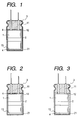
- an anode foil 14 having an anodized film formed on the surface of a valve metal foil and a cathode foil 15 made of a valve metal foil are wound with a separator 16 made of paper or the like to prepare a capacitor element 1.
- the capacitor element thus prepared is inserted into an outer case which is then hermetically sealed with a sealing member.
- a layer of PVA is formed on at least both the upper and lower end faces of the capacitor element.
- the layer of PVA can be formed by applying or spraying PVA onto the upper and lower end faces of the capacitor element so that it is attached thereto.
- PVA to be used herein may be in any form such as powder and fiber so far as it can form a layer on the upper and lower end faces of the capacitor element.
- the layer of PVA may be formed on the side face of the capacitor element.
- a layer of PVA (hereinafter PVA layer) 4 is formed on the end face 12 and the end face 13 of the capacitor element. Referring to the method for forming PVA layer 4, as shown in Fig.
- the anode foil 14 and the cathode foil 15 are wound with the separator 16 to prepare the capacitor element 1 which is then impregnated with the foregoing electrolytic solution.
- PVA layer 4 is formed on the end face 12 and the end face 13 of the capacitor element by any method such as coating.
- the capacitor element thus prepared is inserted into the outer case 2 which is then hermetically sealed with the sealing member 3.
- the capacitor element is then subjected to heat treatment. Thereafter, a voltage is applied to the electrolytic capacitor under heating so that the electrolytic capacitor is subjected to reformation.
- an electrolytic capacitor of the present invention is prepared.
- an electrolytic capacitor can be prepared by forming PVA layer 4 on the end face 12 of the capacitor element 12 alone.
- the capacitor element 1 thus prepared is inserted into the outer case 2 which is then hermetically sealed with the sealing member 3.
- the capacitor element 1 is subjected to heat treatment in such an arrangement that the end face on which PVA layer has been formed is higher in position than the other end face.
- the electrolytic capacitor is positioned as shown in Fig. 2 during the heat treatment.
- a voltage is applied to the electrolytic capacitor under heating so that the electrolytic capacitor is subjected to reformation to prepare an electrolytic capacitor according to the present invention.
- PVA layer may be formed on the end face 13 which faces the inner bottom of the outer case 2.
- heat treatment is effected in such an arrangement that the position of the electrolytic capacitor is reversed from that of Fig. 2.
- the electrolytic capacitor is then subjected to reformation.
- an electrolytic capacitor of the present invention can be prepared by forming PVA layer 4 on the inner bottom 21 of the outer case 2.
- PVA layer can be formed by placing on the inner bottom 21 of the outer case 2 the same PVA as used in the formation of PVA layer on both the two end faces of the capacitor element.
- the capacitor element 1 prepared by winding the anode foil 14 and the cathode foil 15 with the separator 16 is impregnated with the foregoing electrolytic solution, and then inserted into the outer case 2 which is then hermetically sealed with the sealing member 3.
- heat treatment is effected in such an arrangement that the bottom of the outer case faces upward, i.e., the position of the electrolytic capacitor is reversed from that of Fig. 3. Thereafter, the electrolytic capacitor is then subjected to reformation.
- PVA to be used herein there may be used a commercially available PVA.
- PVA having a saponification degree ranging from partially-saponified products having a saponification degree of 75 mol-% to fully saponified products having a saponification degree of not less than 99.5 mol-% may be used.
- the electrolytic capacitor thus prepared exhibits a high withstand voltage and a good overvoltage resistance and maintains a low dielectric loss.
- the electrolytic capacitor of the present invention shows such a behavior can be thought as follows.
- the electrolytic capacitor of the present invention is prepared by a process which comprises inserting a capacitor element 1 into an outer case 2 which is then hermetically sealed with a sealing material 3, and then subjecting the capacitor element to heat treatment so that a PVA layer is formed on both end faces 12 and 13 of the capacitor element.
- a PVA layer is formed on only one end face of the capacitor element, heat treatment is effected in such an arrangement that the end face on which PVA layer has been formed is positioned higher the other end face. Therefore, PVA in PVA layer thus formed reaches the other end face of the capacitor element along the side face of the capacitor element to form another PVA layer thereon.
- the electrolytic solution of the present invention contains boric acid, PVA in these PVA layers is dissolved in the electrolytic solution in a good state. As a result, the electrolytic solution on both the end faces of the capacitor element exhibits a raised sparking voltage.
- the foil which acts as an anode foil for electrolytic capacitor which has been formed is cut to the length according to the size of the capacitor element, and then wound with a separator to prepare an electrolytic capacitor element. Accordingly, the section of the formed foil is exposed at both ends of the capacitor element. Since the sparking voltage of the electrolytic solution present at these areas is raised, the withstand voltage of the section of the formed foil, which exhibits the lowest withstand voltage in the formed foil, can be raised by raising the reformation voltage. As a result, the withstand voltage of the electrolytic capacitor is raised.
- PVA in the PVA layer formed on the end face of the capacitor element is dissolved in the electrolytic solution on the end face of the capacitor element. Since the amount of PVA dissolved in the electrolytic solution contained inside the capacitor element is small enough to prevent the rise in the electrical conductivity of the electrolytic solution, making it possible to keep the dielectric loss of the electrolytic capacitor low.
- an overvoltage when applied to the electrolytic capacitor of the present invention, it is also applied to the anode foil which then generates heat.
- This heat generation causes PVA in the PVA layer formed on the end face of the capacitor element to be rapidly dissolved in the electrolytic solution. This rapidly raises the sparking voltage of the electrolytic solution. As a result, the sparking voltage exceeds the overvoltage, inhibiting ignition.
- the overvoltage is continuously applied to the electrolytic capacitor, the film forming at the oxide layer on the end faces of the capacitor element continues. During this procedure, heat generation and gas production occur, causing the valve of the electrolytic capacitor to open. Thereafter, the solvent component is evaporated away from the electrolytic solution. This causes so-called dry-up state that makes the electrolytic capacitor open.
- the electrolytic solution is free of boric acid, PVA makes the electrolytic solution semisolid when it is dissolved therein. Thus, the withstand voltage of the electrolytic capacitor cannot be raised.
- the withstand voltage of the electrolytic capacitor cannot be raised as high as the present invention.
- the electrolytic solution comprises boric acid incorporated therein to further improve withstand voltage and overvoltage resistance.
- the content of boric acid is from 0.1 to 40 wt-%. If the content of boric acid falls below 0.1 wt-%, the resulting withstand voltage is lowered. On the other hand, if the content of boric acid exceeds 40 wt-%, the resulting tan ⁇ value is raised.
- the first embodiment of the electrolytic solution of the present invention comprises a dicarboxylic acid having side chains, derivative thereof or salt thereof incorporated therein in addition to boric acid.
- the dicarboxylic acid having side chains include 1,6-decanedicarboxylic acid, 5,6-decanedicarboxylic acid, 1,10-decanedicarboxylic acid, 1,7-octanedicarboxylic acid, 2,4,7,6-tetramethyl-1,10decanedicarboxylic acid, 2,4,7,9-tetramethyl-1,6-decanedicarboxylic acid, 2,4,7,6-tetramethyl-5,6-decanedicarboxylic acid, and 7-methyl-7-methoxycarbonyl-1,9-decanedicarboxylic acid.
- Examples of the derivative of these dicarboxylic acids include 7,9-dimethyl-7,9-dimethoxycarbonyl-1,11-dodecanedicarboxylic acid, and 7,8-dimethyl-7,8-dimethoxycarbonyl-1,14-tetradecanedicarboxylic acid.
- the content of the dicarboxylic acid having side chains, derivative thereof or salt thereof (hereinafter referred to as "dicarboxylic acids having side chains") in the electrolytic solution is preferably from 0.1 to 35 wt-%.
- the content of dicarboxylic acids having side chains is from 0.5 to 3 wt-%, and the content of boric acid is from 5 to 40 wt-%.
- the resulting withstand voltage is lowered.
- the resulting withstand voltage is lowered.
- the resulting tan ⁇ value is raised.
- the content of dicarboxylic acids having side chains is from 5 to 25 wt-%, and the content of boric acid is from 0.1 to 5 wt-%.
- the resulting tan ⁇ value is raised.
- the resulting withstand voltage is lowered.
- the resulting withstand voltage is lowered.
- the resulting tan ⁇ value is raised.
- the second embodiment of the electrolytic solution of the present invention comprises a C 6-10 straight-chain aliphatic dicarboxylic acid, aromatic monocarboxylic acid or salt thereof incorporated therein in addition to boric acid.
- the C 6-10 straight-chain aliphatic dicarboxylic acid include adipic acid, pimelic acid, suberic acid, azelaic acid, and sebacic acid.
- the aromatic monocarboxylic acid include benzoic acid, and toluic acid.
- the resulting withstand voltage is lowered.
- the straight-chain aliphatic dicarboxylic acid has more than 11 carbon atoms, the resulting tan ⁇ value is raised.
- the electrolytic solution comprises an aromatic dicarboxylic acid incorporated therein, the resulting withstand voltage is lowered.
- the content of the C 6-10 straight-chain aliphatic dicarboxylic acid, aromatic monocarboxylic acid or salt thereof is preferably from 0.1 to 35 wt-%. If the content of straight-chain aliphatic dicarboxylic acids falls below 0.1 wt-%, the resulting tan ⁇ value is raised. On the contrary, if the content of straight-chain aliphatic dicarboxylic acids exceeds 35 wt-%, the resulting withstand voltage is lowered.
- Examples of the salt of C 6-10 straight-chain aliphatic dicarboxylic acid or aromatic monocarboxylic acid include ammonium salt of these acids, amine salt of these acids, quaternary ammonium salt of these acids, and cyclic amidine compound quaternary salt of these acids.
- Examples of amines constituting the amine salt include primary amine such as methylamine, ethylamine, propylamine, butylamine and ethylenediamine, secondary amine such as dimethylamine, diethylamine, dipropylamine, methylethylamine and diphenylamine, and tertiary amine such as trimethylamine, triethylamine, tripropylamine, triphenylamine and 1,8-diazabicyclo(5,4,0)-undecene-7.
- primary amine such as methylamine, ethylamine, propylamine, butylamine and ethylenediamine
- secondary amine such as dimethylamine, diethylamine, dipropylamine, methylethylamine and diphenylamine
- tertiary amine such as trimethylamine, triethylamine, tripropylamine, triphenylamine and 1,8-diazabicyclo(5,4,0)-unde
- Examples of quaternary ammonium constituting the quaternary ammonium salt include tetraalkylammonium such as tetramethylammonium, tetraethylammonium, tetrapropylammonium, tetrabutylammonium, methyl triethylammonium and dimethyl diethylammonium, and pyridium such as 1-methylpyridium, 1-ethylpyridium, and 1, 3-diethylpyridium.
- Examples of cations constituting the cyclic amidine compound quaternary salt include cations formed by quaterizing the following compounds.
- Imidazole monocyclic compounds e.g., imidazole homologs such as 1-methylimidazole, 1,2-dimethylimidazole, 1,4-dimethyl-2-ethylimidazole and 1-phenylimidazole, oxyalkyl derivatives such as 1-methyl-2-oxymethylimidazole and 1-methyl-2-oxyethylimidazole, nitro and amino derivatives such as 1-methyl-4(5)-nitroimidazole and 1,2-dimethyl-5(4)-aminoimidazole), benzoimidazole (e.g., 1-methylbenzoimidazole, 1-methyl-2-benzylbenzoimidazole), compounds having 2-imidazoline ring (e.g., 1-methylimidazoline, 1,2-dimethylimidazoline, 1,2,4-trimethylimidazoline, 1,4-dimethyl-2-ethylimidazoline, 1-methyl-2-phenylimidazoline), compounds having tetrahydropyrimine ring (
- Examples of the solvent to be used herein include protonic organic polar solvents such as monovalent alcohol (e.g., ethanol, propanol, butanol, pentanol, hexanol, cyclobutanol, cyclopentanol, cyclohexanol, benzyl alcohol), polyvalent alcohol and oxyalcohol compound (e.g., ethylene glycol, propylene glycol, glycerin, methyl cellolsolve, ethyl cellosolve, methoxy propylene glycol, dimethoxy propanol), and aprotic organic polar solvents such as amide (e.g., N-methylformamide, N,N-dimethylformamide, N-ethylformamide, N,N-diethylformamide, N-methylacetamide, N,N-dimethylacetamide, N-ethylacetamide, N,N-diethylacetamide, hexamethylphospho
- the electrolytic solution for electrolytic capacitor according to the present invention can comprise a boric compound such as boric acid, complex compound of boric acid with a polysaccharide (e.g., mannitol, sorbitol) and complex compound of boric acid with a polyvalent alcohol (e.g., ethylene glycol, glycerin), a surface active agent, colloidal silica, etc. incorporated therein to further enhance the withstand voltage.
- a boric compound such as boric acid, complex compound of boric acid with a polysaccharide (e.g., mannitol, sorbitol) and complex compound of boric acid with a polyvalent alcohol (e.g., ethylene glycol, glycerin), a surface active agent, colloidal silica, etc. incorporated therein to further enhance the withstand voltage.
- PVA is not incorporated in the electrolytic solution in the present invention.
- the electrolytic solution of the present invention may comprise various additives incorporated therein for the purpose of lessening leakage current or absorbing hydrogen gas.
- additives include aromatic nitro compounds (e.g., p-nitrobenzoic acid, p-nitrophenol), phosphorus compounds (e.g., phosphoric acid, phosphorous acid, polyphosphoric acid, acidic phosphoric acid ester compound), and oxycarboxylic acid compounds.
- an electrolytic solution containing dicarboxylic acids having side chains and boric acid i.e., first embodiment of the electrolytic solution according to the present invention, if used, exhibits a high sparking voltage and a high electrical conductivity.
- the resulting synergistic effect makes it possible to obtain an electrolytic capacitor having a higher withstand voltage and overvoltage resistance without impairing the dielectric loss.
- an electrolytic solution containing straight-chain aliphatic dicarboxylic acids having side chains and boric acid i.e., second embodiment of the electrolytic solution according to the present invention, if used, exhibits a high electrical conductivity.
- the resulting synergistic effect makes it possible to obtain an electrolytic capacitor having a high withstand voltage suitable for use in middle and high voltage and a low dielectric loss.
- aqueous solution having PVA (saponification degree: 99 mol-%; polymerization degree: 1,700) dissolved therein in an amount of 5% was applied to a separator (manila paper; density: 0.25 g/cm 3 ; thickness: 40 ⁇ m), and then heated and dried to obtain a separator having PVA attached thereto.
- the attached amount of PVA was 10 g/m 2 .
- a cathode foil and an anode foil which has pits with a diameter of not less than 0.1 ⁇ m formed thereon were wound with the separator provided interposed therebetween to prepare a 400 V-10 ⁇ F capacitor element.
- an electrolytic solution comprising 100 parts of ethylene glycol and 15 parts of ammonium 1,6-decanedicarboxylate was prepared.
- the capacitor element thus prepared was impregnated with the electrolytic solution, and then inserted into an aluminum case which was then hermetically sealed with a rubber member.
- 425 V was applied to the electrolytic capacitor at a temperature of 105°C for 3 hours so that the electrolytic capacitor was subjected to reformation.
- the electrolytic solution was gelled.
- an aluminum electrolytic capacitor was prepared.
- An aluminum electrolytic capacitor was prepared in the same manner as in Example 1 except that as the separator there was used a kraft paper having a density of 0.60 g/cm 3 and a thickness of 20 ⁇ m.
- An aluminum electrolytic capacitor was prepared in the same manner as in Example 1 except that as the electrolytic solution there was used one comprising 100 parts of ethylene glycol, 15 parts of ammonium 1,6-decanedicarboxylate and 3 parts of boric acid.
- An aluminum electrolytic capacitor was prepared in the same manner as in Example 2 except that the amount of PVA attached to the separator was 0.05 g/m 2 .
- a cathode foil and an anode foil which has pits with a diameter of not less than 0.1 ⁇ m formed thereon were wound with a separator (kraft paper; density: 0.60 g/cm 3 ; thickness: 40 ⁇ m) provided interposed therebetween to prepare a 400 V-10 ⁇ F capacitor element.
- a separator kraft paper; density: 0.60 g/cm 3 ; thickness: 40 ⁇ m
- an electrolytic solution comprising 100 parts of ethylene glycol and 15 parts of ammonium 1,6-decanedicarboxylate was prepared.
- the capacitor element thus prepared was impregnated with the electrolytic solution, and then inserted into an aluminum case which was then hermetically sealed with a rubber member.
- 425 V was applied to the electrolytic capacitor at a temperature of 105°C for 3 hours so that the electrolytic capacitor was subjected to reformation.
- an aluminum electrolytic capacitor was prepared.
- An aluminum electrolytic capacitor was prepared in the same manner as in Comparative Example 1 except that as the separator there was used a kraft paper having a density of 0.60 g/cm 3 and a thickness of 20 ⁇ m.
- An aluminum electrolytic capacitor was prepared in the same manner as in Comparative Example 1 except that as the separator there was used a manila paper having a density of 0.25 g/cm 3 and a thickness of 40 ⁇ m.
- An aluminum electrolytic capacitor was prepared in the same manner as in Example 1 except that as the anode foil there was used one having pits with a diameter of less than 0.1 ⁇ m formed thereon.
- An aluminum electrolytic capacitor was prepared in the same manner as in Comparative Example 3 except that the capacitor element was impregnated with an electrolytic solution comprising 100 parts of ethylene glycol, 15 parts of ammonium 1, 6-decanedicarboxylate and 11 parts of PVA (saponification degree: 99 mol-%; polymerization degree: 1,700), inserted into an aluminum case which was then hermetically sealed, and then subjected to reformation at 425 V and 105°C for 3 hours while the electrolytic solution was being gelled.
- an electrolytic solution comprising 100 parts of ethylene glycol, 15 parts of ammonium 1, 6-decanedicarboxylate and 11 parts of PVA (saponification degree: 99 mol-%; polymerization degree: 1,700), inserted into an aluminum case which was then hermetically sealed, and then subjected to reformation at 425 V and 105°C for 3 hours while the electrolytic solution was being gelled.
- Example 1 10.01 0.02 - 0.1 0.02
- Example 2 10.05 0.04 - 0.1 0.04
- Example 3 10.08 0.02 0.1 0.02
- Example 4 10.00 0.05 - 0.1 0.06 Comparative Example 1 10.01 0.05 - 0.2 0.07 Comparative Example 2 10.01 0.04 - 0.4 0.07 Comparative Example 3 Shortcircuited during reformation - - Comparative Example 4 2.15 0.09 - - Comparative Example 5 1.08 0.45 - -
- Table 1 shows that the prior art aluminum electrolytic capacitor of Comparative Example 3 comprising a low density separator shows shortcircuiting during reformation while the aluminum electrolytic capacitors of Examples 1 and 3 comprising a low density (0.25 g/cm 3 ) separator show no problems in initial properties and life properties.
- the electrolytic capacitors according to the present invention exhibit an improved withstand voltage, making it possible to use a low separator.
- the use of such a low density separator makes it possible to reduce tan ⁇ from that of Example 2 comprising a separator having a usual density (0.60 g/cm 3 ) as shown in Examples 1 and 3.
- Comparative Example 4 comprising an anode foil having pits with a diameter of less than 0.1 ⁇ m formed thereon and Comparative Example 5 involving the impregnation of the capacitor element with an electrolytic solution containing PVA which is then gelled after capacitor assembly exhibit a low initial capacitance and a high tan ⁇ value and thus cannot provide normal aluminum electrolytic capacitor properties.
- Table 2 shows that in 480V-100 hour overvoltage test the aluminum electrolytic capacitors of Examples 1 to 4 show no shortcircuiting and exhibit an improved overvoltage resistance while the prior art aluminum electrolytic capacitor of Comparative Example 1 and the aluminum electrolytic capacitor of Comparative Example 2 comprising a thin separator (20 ⁇ m) (Comparative Example 2) show shortcircuiting. This means that a thin separator (20 ⁇ m) can be used in the electrolytic capacitor of the present invention as shown in Examples 2 and 4 to reduce the capacitor size.
- the electrolytic capacitor of Example 3 comprising a low density (0.25 g/cm 3 ) separator impregnated with an electrolytic solution containing boric acid shows no shortcircuiting while the electrolytic capacitor of Example 1 comprising the same low density separator impregnated with an ordinary electrolytic solution shows shortcircuiting.
- boric acid in the electrolytic solution makes it possible to further improve the overvoltage resistance.
- the electrolytic capacitor of Example 2 comprising a separator having PVA attached thereto in an amount of 10 g/m 2 shows no shortcircuiting while the electrolytic capacitor of Example 4 comprising a separator having PVA attached thereto in an amount of 0.05 g/m 2 shows shortcircuiting. This means that the attached amount of PVA has an effect on the overvoltage resistance.
- Embodiments of the electrolytic capacitor according to the first aspect of the present invention comprising a PVA-coated separator, an anode foil having pits with a diameter of not less than 0.1 ⁇ m formed thereon and an electrolytic solution containing dicarboxylic acids having side chains and boric acid will be described hereinafter.
- aqueous solution having PVA (saponification degree: 96 mol-%; polymerization degree: 1,700) dissolved therein in an amount of 20% was applied to a separator (kraft paper; density: 0.75 g/cm 3 ; thickness: 50 ⁇ m) by means of a comma reverse type coating machine, and then heated and dried to obtain a separator having PVA attached thereto.
- the attached amount of PVA was 5 g/m 2 .
- a cathode foil and an anode foil which has pits with a diameter of not less than 0.1 ⁇ m formed thereon were then wound with the foregoing separator provided interposed therebetween to prepare a 500V-10 ⁇ F capacitor element.
- an electrolytic solution comprising 100 parts of ethylene glycol, 15 parts of ammonium 1,7-octanedicarboxylate and 3.5 parts of boric acid was prepared.
- the capacitor element thus prepared was impregnated with the foregoing electrolytic solution, inserted into an aluminum case which was then hermetically sealed with a rubber member, and then subjected to reformation at 550 V under heating while the electrolytic solution was being gelled to prepare an aluminum electrolytic capacitor.
- An aluminum electrolytic capacitor was prepared in the same manner as in Example 5 except that as the electrolytic solution there was used one comprising 100 parts of ethylene glycol, 15 parts of ammonium 1,6-decanedicarboxylate and 3.5 parts of boric acid.
- An aluminum electrolytic capacitor was prepared in the same manner as in Example 5 except that as the electrolytic solution there was used one comprising 100 parts of ethylene glycol, 1 part of ammonium 1,6-decanedicarboxylate and 15 parts of boric acid.
- An aluminum electrolytic capacitor was prepared in the same manner as in Example 5 except that as the electrolytic solution there was used one comprising 100 parts of ethylene glycol and 15 parts of ammonium 1,7-octanedicarboxylate.
- An aluminum electrolytic capacitor was prepared in the same manner as in Example 5 except that as the electrolytic solution there was used one comprising 100 parts of ethylene glycol and 30 parts of boric acid.
- An aluminum electrolytic capacitor was prepared in the same manner as in Example 5 except that an ordinary separator was used.
- An aluminum electrolytic capacitor was prepared in the same manner as in Example 5 except that an ordinary separator and an electrolytic solution comprising 100 parts of ethylene glycol, 15 parts of ammonium 1,6-decanedicarboxylate, 3.5 parts of boric acid and 3 parts of PVA were used.
- Example 5 The aluminum electrolytic capacitors of Examples 5 to 7, Comparative Examples 6 to 8 and Conventional Example 1 were each subjected to high-temperature load test at 500 V and 105°C for 2,000 hours. The results are set forth in Table 3. For the high-temperature load test, 20 pieces of the electrolytic capacitor were used for each example. In order to determine various properties, the values were averaged over 20 pieces.
- Table 3 shows that the electrolytic capacitors of Examples 5 to 7 give good results both in initial properties and high-temperature load test.
- the synergistic effect obtained by the improvement of withstand voltage of the electrolytic capacitor of the present invention and the high sparking voltage and electrical conductivity of the electrolytic solution makes it possible to improve withstand voltage without increasing the dielectric loss.
- a high voltage aluminum electrolytic capacitor having a rated voltage of 500 V was realized.
- the electrolytic capacitor of Comparative Example 6 comprising an electrolytic solution free of boric acid
- the electrolytic capacitor of Comparative Example 8 comprising an ordinary separator and the conventional high voltage electrolytic capacitor of Conventional Example 1 show shortcircuiting during reformation.
- the electrolytic capacitor of Comparative Example 7 which comprises boric acid as a main solute to provide a high withstand voltage shows no shortcircuiting during reformation and high-temperature load test but exhibits a raised tan ⁇ value exceeding the maximum allowable range.
- the aluminum electrolytic capacitors of Examples 5 to 7 were each subjected to overvoltage test at 500 V and 600 V at 105°C for 50 hours. The results of the test are set forth in Table 4. For the overvoltage test, 20 pieces of the electrolytic capacitor were used for each example. The number of pieces showing shortcircuiting is set forth in Table 4. Example No. After 550V-50 hrs After 600V-50 hrs Number of pieces showing shortcircuiting Number of pieces showing shortcircuiting Example 5 0 0 Example 6 0 0 Example 7 0 0 0
- Table 4 shows that the electrolytic capacitors of Examples 5 to 7 show no shortcircuiting during 550 V and 600 V overvoltage tests and thus exhibit a good overvoltage resistance.
- Embodiments of the electrolytic capacitor according to the second aspect of the present invention comprising a separator having PVA fibers mixed therein and an electrolytic solution containing dicarboxylic acids having side chains and boric acid will be described hereinafter.
- aqueous solution having PVA (saponification degree: 80 mol-%; polymerization degree: 1,700) dissolved therein in an amount of 35% was extruded into hot air through a spinneret to form a filament which was then wound to prepare a PVA fiber.
- a hemp pulp was subjected to disaggregation, dusting and dehydration, and then beaten.
- the hemp pulp thus treated was then mixed with the foregoing PVA fiber at a ratio of 80 : 20.
- the mixture was then subjected to paper making by means of a cylinder paper machine to prepare an electrolytic paper.
- the electrolytic paper thus prepared was then cut to provide a separator.
- a cathode foil and an anode foil which has pits with a diameter of not less than 0.1 ⁇ m formed thereon and has a withstand voltage of 650 V were wound with the foregoing separator provided interposed therebetween to prepare a 500 V-10 ⁇ F capacitor element.
- an electrolytic solution comprising 100 parts of ethylene glycol, 15 parts of ammonium 1,7-octanedicarboxylate and 3 parts of boric acid was prepared.
- the capacitor element thus prepared was impregnated with the foregoing electrolytic solution, inserted into an aluminum case which was then hermetically sealed with a rubber member, and then subjected to reformation at 550 V under heating to prepare an aluminum electrolytic capacitor.
- An aluminum electrolytic capacitor was prepared in the same manner as in Example 8 except that PVA having a saponification degree of 98 mol-% was used.
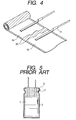
- a cathode foil and an anode foil which has a withstand voltage of 750 V were then wound with the foregoing separator provided interposed therebetween to prepare a 500 V-10 ⁇ F capacitor element as shown in Fig. 4.
- an electrolytic solution comprising 100 parts of ethylene glycol, 15 parts of ammonium 1,7-octanedicarboxylate and 3.5 parts of boric acid was prepared.
- the capacitor element thus prepared was impregnated with the foregoing electrolytic solution, inserted into an aluminum case which was then hermetically sealed with a rubber member, and then subjected to reformation at 550 V under heating to prepare an aluminum electrolytic capacitor.
- An aluminum electrolytic capacitor was prepared in the same manner as in Example 10 except that as the electrolytic solution there was used one comprising 100 parts of ethylene glycol, 15 parts of ammonium 1,6-decanedicarboxylate and 3.5 parts of boric acid.
- An aluminum electrolytic capacitor was prepared in the same manner as in Example 10 except that as the electrolytic solution there was used one comprising 100 parts of ethylene glycol, 10 parts of boric acid and 1 part of ammonium 1,6-decanedicarboxylate into which ammonium gas had been bubbled.
- An aluminum electrolytic capacitor was prepared in the same manner as in Example 8 except that as the fiber to be mixed in the separator there was used an ordinary vinylon.
- the vinylon used is called vinylon staple obtained by a process which comprises spinning a yarn from an aqueous solution of PVA in a sodium sulfate solution, and then subjecting the yarn to heat treatment, drawing and acetalation to form fibers.
- An aluminum electrolytic capacitor was prepared in the same manner as in Example 8 except that as the fiber to be mixed in the separator there was used a fiber formed by wet spinning process.
- This fiber was obtained by a process which comprises spinning a yarn from an aqueous solution of PVA in a sodium sulfate solution in the same manner as vinylon staple, and then subjecting the yarn to wet heat drawing in a high temperature aqueous solution of Glauber's salt, heat drawing and heat treatment to form fibers.
- An aluminum electrolytic capacitor was prepared in the same manner as in Example 8 except that as the fiber to be mixed in the separator there was used a fiber formed by an ordinary dry spinning process. This fiber was obtained by a process which comprises spinning a yarn from an aqueous solution of PVA in hot air, and then subjecting the yarn to dry heat drawing and heat treatment.
- An aluminum electrolytic capacitor was prepared in the same manner as in Example 10 except that as the electrolytic solution there was used one comprising 100 parts of ethylene glycol and 15 parts of ammonium 1,7-octanedicarboxylate.
- An aluminum electrolytic capacitor was prepared in the same manner as in Example 10 except that as the electrolytic solution there was used one comprising 100 parts of ethylene glycol and 30 parts of boric acid into which ammonia gas had been injected.
- An aluminum electrolytic capacitor was prepared in the same manner as in Example 8 except that as the separator there was used an ordinary hemp paper free of PVA fibers.
- An aluminum electrolytic capacitor was prepared in the same manner as in Example 8 except that as the separator there was used an ordinary hemp paper free of PVA fibers and PVA (saponification degree: 98.5 mol-%; polymerization degree: 330) was incorporated in the electrolytic solution in an amount of 3%.
- An aluminum electrolytic capacitor was prepared in the same manner as in Example 8 except that as the separator there was used an ordinary hemp paper free of PVA fibers and as the electrolytic solution there was used one comprising 100 parts of ethylene glycol and 5 parts of ammonium 1,6-decanedicarboxylate.
- An aluminum electrolytic capacitor was prepared in the same manner as in Example 10 except that as the separator there was used an ordinary separator and as the electrolytic solution there was used one comprising 100 parts of ethylene glycol and 5 parts of ammonium 1,6-decanedicarboxylate.
- the aluminum electrolytic capacitors of Examples 8 and 9, Comparative Examples 9 to 11 and Conventional Examples 2 to 4 were each subjected to high-temperature load test at 500 V and 105°C for 2,000 hours.
- the results of the high-temperature load test are set forth in Table 5.
- the aluminum electrolytic capacitors of Examples 10 to 12, Comparative Examples 12 and 13 and Conventional Example 5 were each subjected to high-temperature load test at 500 V and 105°C for 1,000 hours.
- the results of the high-temperature load test are set forth in Table 6.
- 20 pieces of the electrolytic capacitor were used for each example. In order to determine various properties, the value of 20 pieces were averaged.
- the electrolytic capacitor of Comparative Example 11 comprising a separator having a fiber formed by dry spinning process mixed therein and the electrolytic capacitor of Conventional Example 4 comprising an ordinary electrolytic paper and an electrolytic solution having 5 parts of 1,6-decanedicarboxylic acid incorporated therein as a solute show no shortcircuiting during reformation but show shortcircuiting during 105°C-2000 hr load test and thus exhibit an insufficient withstand voltage.
- the electrolytic capacitors of Conventional Examples 2 and 3 exhibit a reformable voltage of 400 V and 450 V, respectively, and a maximum allowable voltage of 350 V and 400 V, respectively.
- the electrolytic solutions of Conventional Examples 2 and 3 exhibit an electrical conductivity of 2.3 mS/cm and 2.0 mS/cm, respectively.
- the electrolytic capacitors which had been subjected to reformation at the respective reformation voltage exhibited a tan ⁇ value of 0.025 and 0.030, respectively.
- the electrolytic capacitor of Example 8 comprising a separator having PVA fiber made of PVA having a saponification degree of 80 mol-% mixed therein and the electrolytic capacitor of Example 9 comprising a separator having PVA fiber made of PVA having a saponification degree of 98 mol-% mixed therein maintain good properties even after 2,000 hours of 105°C load test.
- these electrolytic capacitors exhibit a maximum allowable voltage of not less than 500 V.
- the electrolytic capacitors of these examples show a withstand voltage rise of not less than 100 V.
- Example 8 a voltage was applied at a constant current. As a result, it was found that the voltage reached 650 V, which is the withstand voltage of the anode foil.
- the electrolytic capacitors of the present invention exhibit a drastically increased withstand voltage.
- the initial tan ⁇ value of these electrolytic capacitors remain the same as that of the electrolytic capacitor of Conventional Example 2 comprising an ordinary electrolytic paper and an ordinary electrolytic solution and are lower than that of the electrolytic capacitor of Conventional Example 3 comprising an ordinary electrolytic paper and an electrolytic solution comprising PVA dissolved therein. Further, the initial tan ⁇ value of these electrolytic capacitors are each about half that of the electrolytic capacitor of Conventional Example 4 comprising 5 parts of 1, 6-decanedicarboxylic acid as a solute. Thus, the electrolytic capacitors according to the present invention remain the same as the conventional middle and high voltage electrolytic capacitors in dielectric loss.
- the initial tan ⁇ value of the electrolytic capacitors of Examples 10 to 12 are each about 1/5 to 1/2 of that of the electrolytic capacitors of Comparative Example 3 and Conventional Example 5.
- the electrolytic capacitors of Examples 10 to 12 show little change in tan ⁇ even after 2,000 hours of 105°C load test.
- the synergistic effect obtained by the high withstand voltage of the electrolytic capacitor of the present invention and the electrolytic solution having a high sparking voltage and electrical conductivity makes it possible to obtain a high withstand voltage while maintaining a low dielectric loss and hence realize an electrolytic capacitor having a rated voltage of 500 V.
- Embodiments of the electrolytic capacitor according to the third aspect of the present invention comprising PVA attached to both end faces of the capacitor element and an electrolytic solution containing dicarboxylic acids having side chains and boric acid will be described hereinafter.
- an anode foil 14 having an oxide layer formed on the surface of a roughened aluminum foil and a cathode foil 15 made of aluminum were wound with a separator 16 made of paper or the like provided interposed therebetween to prepare a capacitor element 1.
- the capacitor element 1 was then impregnated with a driving electrolytic solution comprising 100 parts of ethylene glycol, 15 parts of ammonium 1,7-octanedicarboxylate and 3 parts of boric acid. 1.
- a PVA powder was then attached to the end faces 12 and 13 of the capacitor element as shown in Fig. 1.
- the capacitor element thus prepared was inserted into a closed-end cylindrical outer case 2 which was then hermetically sealed with a sealing member, subjected to heat treatment at 85°C, and then subjected to reformation at 550 V to prepare an aluminum electrolytic capacitor.
- the rated voltage and capacitance of the aluminum electrolytic capacitor thus prepared were 500 V and 10 ⁇ F, respectively.
- Example 13 a PVA powder was attached to both end faces 12 and 13 of a capacitor element impregnated with an electrolytic solution.
- PVA was attached to only the end face 12 of a capacitor element impregnated with an electrolytic solution.
- the electrolytic capacitor was then subjected to heat treatment in such an arrangement that it was positioned as shown in Fig. 2.
- Example 13 a PVA powder was attached to both end faces 12 and 13 of a capacitor element impregnated with an electrolytic solution.
- PVA was placed on the inner bottom 21 of the outer case to prepare an aluminum electrolytic capacitor. Heat treatment was effected in such an arrangement that the bottom of the capacitor faces upward, i.e., the position of the capacitor is reversed from that of Fig. 3.
- An aluminum electrolytic capacitor was prepared in the same manner as in Example 13 except that as the electrolytic solution there was used one comprising 100 parts of ethylene glycol and 15 parts of ammonium 1,7-octanedicarboxylic acid.
- An aluminum electrolytic capacitor was prepared in the same manner as in Example 13 except that no PVA was used.
- Embodiments of the electrolytic capacitor according to the first to third aspects of the present invention comprising an electrolytic solution containing straight-chain dicarboxylic acids and boric acid will be described hereinafter.
- a cathode foil and an anode foil which has a withstand voltage of 650 V were then wound with the foregoing separator provided interposed therebetween to prepare a capacitor element as shown in Fig. 4.
- an electrolytic solution comprising 100 parts of ethylene glycol, 10 parts of ammonium adipate and 3 parts of boric acid was prepared.
- the capacitor element thus prepared was impregnated with the foregoing electrolytic solution, inserted into an aluminum case which was then hermetically sealed with a rubber member, and then subjected to reformation at 450 V under heating to prepare an aluminum electrolytic capacitor having a rated voltage of 400 V and a rated capacitance of 10 ⁇ F.
- an anode foil 14 having an oxide layer formed on the surface of a roughened aluminum foil and a cathode foil 15 made of aluminum were wound with a separator 12 made of paper or the like provided interposed therebetween to prepare a capacitor element 1.
- the capacitor element 1 was then impregnated with a driving electrolytic solution comprising 100 parts of ethylene glycol, 10 parts of ammonium adipate and 3 parts of boric acid.
- a PVA powder was then applied to the end faces 12 and 13 of the capacitor element to form a PVA layer thereof as shown in Fig. 1.
- the capacitor element thus prepared was inserted into a closed-end cylindrical outer case 2 which was then hermetically sealed with a sealing member, heated, and then subjected to reformation at 450 V to prepare an aluminum electrolytic capacitor.
- the rated voltage and capacitance of the aluminum electrolytic capacitor thus prepared were 400 V and 10 ⁇ F, respectively.
- aqueous solution having PVA (saponification degree: 96 mol-%; polymerization degree: 1,700) dissolved therein in an amount of 20% was applied to a separator (kraft paper; density: 0.75 g/cm 3 ; thickness: 50 ⁇ m) by means of a comma reverse type coating machine, and then heated and dried to obtain a separator having PVA attached thereto.
- the attached amount of PVA was 5 g/m 2 .
- a cathode foil and an anode foil which has pits with a diameter of not less than 0.1 ⁇ m formed thereon were then wound with the foregoing separator provided interposed therebetween to prepare a 400V-10 ⁇ F capacitor element.
- an electrolytic solution comprising 100 parts of ethylene glycol, 10 parts of ammonium adipate and 3 parts of boric acid was prepared.
- the capacitor element thus prepared was impregnated with the foregoing electrolytic solution, inserted into an aluminum case which was then hermetically sealed with a rubber member, and then subjected to reformation at 450 V under heating while the electrolytic solution was being gelled to prepare an aluminum electrolytic capacitor.
- An aluminum electrolytic capacitor was prepared in the same manner as in Example 16 except that as the electrolytic solution there was used one comprising 100 parts of ethylene glycol and 10 parts of ammonium adipate.
- An aluminum electrolytic capacitor was prepared in the same manner as in Example 16 except that an ordinary separator was used.
- An aluminum electrolytic capacitor was prepared in the same manner as in Example 18 except that as the electrolytic solution there was used one comprising 100 parts of ethylene glycol and 10 parts of ammonium adipate.
- An aluminum electrolytic capacitor was prepared in the same manner as in Example 18 except that an ordinary separator was used.
- An aluminum electrolytic capacitor was prepared in the same manner as in Example 16 except that as the separator there was used an ordinary separator and as the electrolytic solution there was used one comprising 100 parts of ethylene glycol and 15 parts of ammonium 1,7-octanedicarboxylate.
- An aluminum electrolytic capacitor was prepared in the same manner as in Example 18 except that as the separator there was used an ordinary separator and as the electrolytic solution there was used one comprising 100 parts of ethylene glycol, 15 parts of ammonium 1,7-octanedicarboxylate, 3.5 parts of boric acid and 3 parts of PVA.
- the electrolytic capacitor of Comparative Example 15 comprising an electrolytic solution free of boric acid and the electrolytic capacitor of Comparative Example 16 comprising an ordinary separator show shortcircuiting during reformation.
- these examples cannot provide a withstand voltage that allows the preparation of an electrolytic capacitor having a rated voltage of 400 V.
- the electrolytic capacitor of Conventional Example 7 comprising an electrolytic solution containing boric acid which is an electrolytic solution for conventional 400 V electrolytic capacitor using ammonium 1,7-octanedicarboxylate exhibits a high tan ⁇ value at the initial stage and after high-temperature load test.
- the tan ⁇ value of the electrolytic capacitors of Examples 16 and 17 are about half that of the conventional example at the initial stage and after the load test. Thus, these electrolytic capacitors exhibit a reduced dielectric loss.
- Embodiments of the electrolytic capacitor according to the first and second aspects of the present invention comprising an electrolytic solution containing other straight-chain dicarboxylic acids and boric acid will be described hereinafter.
- An aluminum electrolytic capacitor having a rated voltage of 450 V and a rated capacitance of 10 ⁇ m was prepared in the same manner as in Example 16 except that as the anode foil there was used one having a withstand voltage of 700 V, as the electrolytic solution there was used one comprising 100 parts of ethylene glycol, 10 parts of ammonium benzoate and 3 parts of boric acid, and the electrolytic capacitor was subjected to reformation at 500 V.
- An aluminum electrolytic capacitor was prepared in the same manner as in Example 18 except that a 450 V-10 ⁇ F capacitor element was used, an electrolytic solution comprising 100 parts of ethylene glycol, 10 parts of ammonium benzoate and 3 parts of boric acid was used, and the electrolytic capacitor was subjected to reformation at 500 V.
- An aluminum electrolytic capacitor was prepared in the same manner as in Example 19 except that as the electrolytic solution there was used one comprising 100 parts of ethylene glycol and 10 parts of ammonium benzoate.
- An aluminum electrolytic capacitor was prepared in the same manner as in Example 19 except that an ordinary separator was used.
- An aluminum electrolytic capacitor was prepared in the same manner as in Example 20 except that an ordinary separator was used.
- An aluminum electrolytic capacitor was prepared in the same manner as in Example 19 except that as the separator there was used an ordinary separator and as the electrolytic solution there was used one comprising 100 parts of ethylene glycol, 15 parts of ammonium 1,6-decanedicarboxylate and 3 parts of boric acid.
- An aluminum electrolytic capacitor was prepared in the same manner as in Example 20 except that as the separator there was used an ordinary separator and as the electrolytic solution there was used one comprising 100 parts of ethylene glycol, 15 parts of ammonium 1,6-octanedicarboxylate, 10 parts of boric acid and 3 parts of PVA.
- the electrolytic capacitor of Comparative Example 19 comprising an electrolytic solution free of boric acid and the electrolytic capacitor of Comparative Example 20 comprising an ordinary separator show shortcircuiting during reformation.
- these examples cannot provide a withstand voltage that allows the preparation of an electrolytic capacitor having a rated voltage of 450 V.
- the electrolytic capacitor of Conventional Example 9 comprising an electrolytic solution containing 1,6-decanedicarboxylic acid which is an electrolytic solution for conventional 450 V electrolytic capacitor exhibits a high tan ⁇ value at the initial stage and after high-temperature load test.
- the tan ⁇ value of the electrolytic capacitor of Example 19 is about one third of that of Conventional Example 9 at the initial stage and after the load test.
- the electrolytic capacitor of Comparative Example 21 comprising an ordinary separator shows shortcircuiting during reformation, demonstrating the effect of the separator of the present invention.
- the tan ⁇ value of the electrolytic capacitor of Example 20 is half that of the electrolytic capacitor of Conventional Example 10 at the initial stage and after high-temperature load test.
- the electrolytic capacitor of Example 20 is an aluminum electrolytic capacitor having a low dielectric loss.
- the synergistic effect obtained by the improvement of withstand voltage of the present invention and the high electrical conductivity of the electrolytic solution makes it possible to realize an aluminum electrolytic capacitor for middle and high voltage having an unprecedentedly low dielectric loss, i.e., tan ⁇ value reduced to 1/3 to 1/2 of the conventional example.
- the electrolytic capacitor according to the first aspect of the present invention comprises a capacitor element formed by winding an anode foil having pits with a diameter of not less than 0.1 ⁇ m formed on the surface thereof and a cathode foil with a separator provided interposed therebetween, said separator having been coated with PVA which is then dried, said capacitor element being in contact with an electrolytic solution for electrolytic capacitor containing ethylene glycol, whereby said electrolytic solution is gelled.
- the electrolytic capacitor according to the second aspect of the present invention comprises a capacitor element formed by winding an anode foil and a cathode foil with a separator provided interposed therebetween, said separator having been prepared by mixing filament fibers formed by extruding PVA solution into a gas, said capacitor element being impregnated with an electrolytic solution.
- the electrolytic capacitor according to the third aspect of the present invention is prepared by a process which comprises impregnating a capacitor element formed by winding an anode foil, a cathode foil and a separator with a driving electrolytic solution, inserting said capacitor element into an outer case, sealing the opening of said outer case with a sealing member, and then subjecting said anode to reformation, wherein said driving electrolytic solution contains boric acid and a polyvinyl alcohol is attached to at least both the upper and lower end faces of said capacitor element.
- a driving electrolytic solution contains boric acid and a polyvinyl alcohol is attached to at least both the upper and lower end faces of said capacitor element.
- the electrolytic solution contains dicarboxylic acids having side chains and boric acid, it exhibits a high sparking voltage and a high electrical conductivity. Therefore, the synergistic effect obtained by electrolytic capacitor and electrolytic solution makes it possible to obtain an electrolytic capacitor for middle and high voltage having a higher withstand voltage and a high overvoltage resistance without impairing the dielectric loss.
- the electrolytic solution to be used comprises straight-chain aliphatic dicarboxylic acids and boric acid, it exhibits a high electrical conductivity, and the resulting synergistic effect obtained by electrolytic capacitor and electrolytic solution makes it possible to obtain an electrolytic capacitor having a withstand voltage suitable for use in middle and high voltage range and a low dielectric loss. Further, a high overvoltage resistance can be obtained.
Landscapes
- Engineering & Computer Science (AREA)
- Power Engineering (AREA)
- Microelectronics & Electronic Packaging (AREA)
- Chemical & Material Sciences (AREA)
- Chemical Kinetics & Catalysis (AREA)
- Electrochemistry (AREA)
- Fixed Capacitors And Capacitor Manufacturing Machines (AREA)
- Electric Double-Layer Capacitors Or The Like (AREA)
Applications Claiming Priority (15)
| Application Number | Priority Date | Filing Date | Title |
|---|---|---|---|
| JP28777397 | 1997-10-03 | ||
| JP287773/97 | 1997-10-03 | ||
| JP28777397A JP3918893B2 (ja) | 1997-10-03 | 1997-10-03 | 電解コンデンサ |
| JP10022898A JP4811969B2 (ja) | 1998-03-27 | 1998-03-27 | 電解コンデンサおよびその製造方法 |
| JP100228/98 | 1998-03-27 | ||
| JP10022898 | 1998-03-27 | ||
| JP13124398A JPH11307395A (ja) | 1998-04-24 | 1998-04-24 | 電解コンデンサ |
| JP131243/98 | 1998-04-24 | ||
| JP13124398 | 1998-04-24 | ||
| JP16432898A JPH11340095A (ja) | 1998-05-28 | 1998-05-28 | 電解コンデンサ |
| JP16432898 | 1998-05-28 | ||
| JP164328/98 | 1998-05-28 | ||
| JP202790/98 | 1998-07-02 | ||
| JP20279098 | 1998-07-02 | ||
| JP20279098A JP4304384B2 (ja) | 1998-07-02 | 1998-07-02 | 電解コンデンサ |
Publications (3)
| Publication Number | Publication Date |
|---|---|
| EP0907191A2 true EP0907191A2 (fr) | 1999-04-07 |
| EP0907191A3 EP0907191A3 (fr) | 2004-01-28 |
| EP0907191B1 EP0907191B1 (fr) | 2006-10-04 |
Family
ID=27526000
Family Applications (1)
| Application Number | Title | Priority Date | Filing Date |
|---|---|---|---|
| EP98114982A Expired - Lifetime EP0907191B1 (fr) | 1997-10-03 | 1998-08-10 | Condensateur électrolytique |
Country Status (5)
| Country | Link |
|---|---|
| US (1) | US6058006A (fr) |
| EP (1) | EP0907191B1 (fr) |
| KR (1) | KR100577618B1 (fr) |
| DE (1) | DE69836059T2 (fr) |
| TW (1) | TW388891B (fr) |
Cited By (2)
| Publication number | Priority date | Publication date | Assignee | Title |
|---|---|---|---|---|
| CN106771645A (zh) * | 2016-12-12 | 2017-05-31 | 国网四川省电力公司电力科学研究院 | 电容式电压互感器介损及电容量在线监测方法及监测系统 |
| CN111919270A (zh) * | 2018-03-28 | 2020-11-10 | 松下知识产权经营株式会社 | 带座板电容器 |
Families Citing this family (31)
| Publication number | Priority date | Publication date | Assignee | Title |
|---|---|---|---|---|
| DE69832815T2 (de) * | 1997-11-28 | 2006-09-14 | Nippon Chemi-Con Corp., Ome | Elektrolytkondensator |
| JPH11265839A (ja) * | 1998-03-17 | 1999-09-28 | Matsushita Electric Ind Co Ltd | アルミニウム電解コンデンサ |
| US6275729B1 (en) * | 1998-10-02 | 2001-08-14 | Cardiac Pacemakers, Inc. | Smaller electrolytic capacitors for implantable defibrillators |
| JP4554012B2 (ja) * | 1998-10-13 | 2010-09-29 | パナソニック株式会社 | アルミニウム電解コンデンサ |
| JP3366268B2 (ja) * | 1998-12-01 | 2003-01-14 | ルビコン株式会社 | 電解コンデンサ駆動用電解液及びこれを使用した電解コンデンサ |
| JP3623113B2 (ja) | 1998-12-03 | 2005-02-23 | ルビコン株式会社 | 電解コンデンサ |
| FR2788877B1 (fr) * | 1999-01-27 | 2001-11-09 | Nichicon Corp | Condensateur electrolytique d'aluminium |
| US6396682B1 (en) * | 2000-01-31 | 2002-05-28 | Ness Capacitor Co., Ltd. | Electric energy storage device and method for manufacturing the same |
| TW521289B (en) * | 2001-01-17 | 2003-02-21 | Matsushita Electric Industrial Co Ltd | Electronic component |
| CN101853739B (zh) * | 2002-03-28 | 2012-05-09 | 日本贵弥功株式会社 | 固体电解电容器及其制造方法 |
| CN100590760C (zh) * | 2002-03-28 | 2010-02-17 | 日本贵弥功株式会社 | 固体电解电容器及其制造方法 |
| KR100477245B1 (ko) * | 2002-07-05 | 2005-03-17 | 현대모비스 주식회사 | 에어백 모듈 일체형 혼 스위치 |
| US6917094B2 (en) * | 2002-11-29 | 2005-07-12 | Honda Motor Co., Ltd | Electrode for electric double layer capacitor |
| KR100462081B1 (ko) * | 2002-12-11 | 2004-12-17 | 파츠닉(주) | 알루미늄 전해콘덴서의 고압용 전해액 조성물 |
| US7268996B1 (en) * | 2003-01-10 | 2007-09-11 | Pacesetter, Inc. | Electrolyte for very high voltage electrolytic capacitors |
| US6967828B2 (en) * | 2003-05-30 | 2005-11-22 | Medtronic, Inc. | Capacitors including metalized separators |
| US7242572B2 (en) * | 2003-05-30 | 2007-07-10 | Medtronic, Inc. | Methods of applying separator members to an electrode of a capacitor |
| US6985352B2 (en) * | 2003-05-30 | 2006-01-10 | Medtronic, Inc. | Capacitors including track-etched separator materials |
| US6995971B2 (en) | 2003-05-30 | 2006-02-07 | Medtronic, Inc. | Capacitors including interacting separators and surfactants |
| US7163643B2 (en) * | 2003-06-26 | 2007-01-16 | Matsushita Electric Industrial Co., Ltd. | Driving electrolyte and electrolytic capacitor using the same |
| KR100561265B1 (ko) | 2004-03-25 | 2006-03-14 | 파츠닉(주) | 알루미늄 전해콘덴서 초고압용 전해액 |
| KR100561264B1 (ko) | 2004-03-25 | 2006-03-14 | 파츠닉(주) | 알루미늄 전해콘덴서 초고압용 전해액 |
| JP4660222B2 (ja) * | 2005-02-14 | 2011-03-30 | 三洋電機株式会社 | 固体電解コンデンサ及びその製造方法 |
| US7206186B1 (en) * | 2006-05-31 | 2007-04-17 | Cornell Dubilier Marketing, Inc. | Hermetically sealed electrolytic capacitor |
| TW201015595A (en) * | 2008-09-22 | 2010-04-16 | Sanyo Electric Co | Winding-type electrolytic capacitor and method of manufacturing the same |
| TWI447766B (zh) * | 2009-03-31 | 2014-08-01 | Nippon Chemicon | Electrolyte for Aluminum Electrolytic Capacitors and Aluminum Electrolytic Capacitors |
| US8318037B2 (en) | 2010-04-30 | 2012-11-27 | Wisconsin Alumni Research Foundation | Organosilicon glycol-based electrolytes with a hydroxy terminus |
| CN102523759B (zh) * | 2010-09-10 | 2013-08-14 | 松下电器产业株式会社 | 电子部件及电子部件用导线 |
| JP6314680B2 (ja) * | 2014-06-18 | 2018-04-25 | 日本ケミコン株式会社 | コンデンサ及びコンデンサの製造方法 |
| TWI650784B (zh) * | 2016-11-01 | 2019-02-11 | 鈺邦科技股份有限公司 | 不需要負極導電箔片的捲繞型電容器封裝結構及其捲繞式組件 |
| CN113502684B (zh) * | 2021-06-21 | 2022-10-14 | 浙江鹏辰造纸研究所有限公司 | 一种锌银电池用辅助隔膜及其制备方法 |
Family Cites Families (15)
| Publication number | Priority date | Publication date | Assignee | Title |
|---|---|---|---|---|
| GB1049058A (en) * | 1963-10-08 | 1966-11-23 | Safco Condensateurs | mprovements in or relating to electrolytes for electrolytic capacitors and capacitors employing same |
| US4447346A (en) * | 1977-10-11 | 1984-05-08 | Sangamo Weston, Inc. | Electrolyte system for electrolytic capacitors |
| US4480290A (en) * | 1979-07-17 | 1984-10-30 | Les Condensateurs Sic Safco | Electrolytic capacitor including a composite separator between the anode and the cathode thereof |
| JPS56139113A (en) * | 1980-04-01 | 1981-10-30 | Asahi Chem Ind Co Ltd | Manufacture of filter |
| EP0421487A3 (en) * | 1986-05-20 | 1991-07-24 | Showa Denko Kabushiki Kaisha | Solid electrolytic capacitor |
| DE3773870D1 (de) * | 1986-12-24 | 1991-11-21 | Showa Aluminium Co Ltd | Eine aluminium-kondensatorelektrode fuer elektrolytische kondensatoren und verfahren zu ihrer herstellung. |
| US4812145A (en) * | 1987-12-22 | 1989-03-14 | Lydall, Inc. | Process for the production of a battery separator |
| DE69023780T2 (de) * | 1989-01-11 | 1996-04-18 | Matsushita Electric Ind Co Ltd | Elektrolyt zur Verwendung in elektrolytischen Kondensatoren. |
| JP2772297B2 (ja) * | 1990-04-11 | 1998-07-02 | ジエルマックス株式会社 | 電解コンデンサ |
| JPH0458508A (ja) * | 1990-06-28 | 1992-02-25 | Nippon Chemicon Corp | 電解コンデンサ |
| DE69301860T2 (de) * | 1992-05-12 | 1996-08-01 | Japan Vilene Co Ltd | Trennschicht für Elektrolytkondensatoren |
| JP3324803B2 (ja) * | 1992-11-27 | 2002-09-17 | 株式会社クラレ | 電解コンデンサー用セパレーター |
| KR970008554B1 (ko) * | 1994-06-30 | 1997-05-27 | 삼성전기 주식회사 | 알루미늄 전해콘덴서용 전해액 |
| US5661629A (en) * | 1995-06-06 | 1997-08-26 | Macfarlane; Douglas Robert | High conductivity crosslinked electrolyte materials and capacitors incorporating the same |
| JPH10223481A (ja) * | 1997-02-10 | 1998-08-21 | Nippon Chemicon Corp | 電解コンデンサ |
-
1998
- 1998-08-10 US US09/131,679 patent/US6058006A/en not_active Expired - Lifetime
- 1998-08-10 DE DE69836059T patent/DE69836059T2/de not_active Expired - Lifetime
- 1998-08-10 TW TW087113219A patent/TW388891B/zh not_active IP Right Cessation
- 1998-08-10 KR KR1019980032363A patent/KR100577618B1/ko not_active Expired - Lifetime
- 1998-08-10 EP EP98114982A patent/EP0907191B1/fr not_active Expired - Lifetime
Cited By (4)
| Publication number | Priority date | Publication date | Assignee | Title |
|---|---|---|---|---|
| CN106771645A (zh) * | 2016-12-12 | 2017-05-31 | 国网四川省电力公司电力科学研究院 | 电容式电压互感器介损及电容量在线监测方法及监测系统 |
| CN106771645B (zh) * | 2016-12-12 | 2019-06-25 | 国网四川省电力公司电力科学研究院 | 电容式电压互感器介损及电容量在线监测方法及监测系统 |
| CN111919270A (zh) * | 2018-03-28 | 2020-11-10 | 松下知识产权经营株式会社 | 带座板电容器 |
| CN111919270B (zh) * | 2018-03-28 | 2022-07-05 | 松下知识产权经营株式会社 | 带座板电容器 |
Also Published As
| Publication number | Publication date |
|---|---|
| DE69836059D1 (de) | 2006-11-16 |
| TW388891B (en) | 2000-05-01 |
| EP0907191B1 (fr) | 2006-10-04 |
| EP0907191A3 (fr) | 2004-01-28 |
| DE69836059T2 (de) | 2007-05-10 |
| KR100577618B1 (ko) | 2006-11-30 |
| KR19990036589A (ko) | 1999-05-25 |
| US6058006A (en) | 2000-05-02 |
Similar Documents
| Publication | Publication Date | Title |
|---|---|---|
| US6058006A (en) | Electrolytic capacitor | |
| EP0938108B1 (fr) | Condensateur électrolytique et son procédé de fabrication | |
| JP5934878B2 (ja) | 電解コンデンサおよびその製造方法 | |
| US8462484B2 (en) | Method for manufacturing electrolytic capacitor with electrically conductive solid layer and electrolytic capacitor with electrically conductive solid layer | |
| US10692657B2 (en) | Electrolytic capacitor and method for manufacturing same | |
| US10734163B2 (en) | Electrolytic capacitor and manufacturing method therefor | |
| US11935704B2 (en) | Electrolytic capacitor comprising an electrolytic solution containing a first base component, a first acid component, and a second acid component | |
| US11177080B2 (en) | Conductive polymer hybrid type electrolytic capacitor | |
| US20260011508A1 (en) | Electrolytic capacitor and production method therefor | |
| US12266481B2 (en) | Electrolytic capacitor including electrolytic solution having high electrical conductivity and method for producing same | |
| WO2025070417A1 (fr) | Condensateur à électrolyte solide et procédé de fabrication | |
| JP4617529B2 (ja) | 電解コンデンサ | |
| JP4304384B2 (ja) | 電解コンデンサ | |
| JPH11307395A (ja) | 電解コンデンサ | |
| JP3918893B2 (ja) | 電解コンデンサ | |
| JPH11340095A (ja) | 電解コンデンサ | |
| JP4646462B2 (ja) | 電解コンデンサ | |
| US11244792B2 (en) | Electrolytic capacitor | |
| JP4496580B2 (ja) | 電解コンデンサ | |
| TW202603760A (zh) | 電解液、電解電容器及電解電容器之製造方法 | |
| JP2001196269A (ja) | 電解コンデンサ | |
| WO2023190189A1 (fr) | Condensateur électrolytique à enroulement | |
| JP2000286160A (ja) | 電解コンデンサ | |
| JP2000294456A (ja) | 電解コンデンサ | |
| JP2000294457A (ja) | 電解コンデンサ |
Legal Events
| Date | Code | Title | Description |
|---|---|---|---|
| PUAI | Public reference made under article 153(3) epc to a published international application that has entered the european phase |
Free format text: ORIGINAL CODE: 0009012 |
|
| AK | Designated contracting states |
Kind code of ref document: A2 Designated state(s): AT BE CH CY DE DK ES FI FR GB GR IE IT LI LU MC NL PT SE |
|
| AX | Request for extension of the european patent |
Free format text: AL;LT;LV;MK;RO;SI |
|
| PUAL | Search report despatched |
Free format text: ORIGINAL CODE: 0009013 |
|
| RIC1 | Information provided on ipc code assigned before grant |
Ipc: 7H 01G 9/02 B Ipc: 7H 01G 9/035 A |
|
| AK | Designated contracting states |
Kind code of ref document: A3 Designated state(s): AT BE CH CY DE DK ES FI FR GB GR IE IT LI LU MC NL PT SE |
|
| AX | Request for extension of the european patent |
Extension state: AL LT LV MK RO SI |
|
| 17P | Request for examination filed |
Effective date: 20040430 |
|
| AKX | Designation fees paid |
Designated state(s): DE FR GB NL |
|
| 17Q | First examination report despatched |
Effective date: 20050531 |
|
| GRAP | Despatch of communication of intention to grant a patent |
Free format text: ORIGINAL CODE: EPIDOSNIGR1 |
|
| GRAS | Grant fee paid |
Free format text: ORIGINAL CODE: EPIDOSNIGR3 |
|
| GRAA | (expected) grant |
Free format text: ORIGINAL CODE: 0009210 |
|
| AK | Designated contracting states |
Kind code of ref document: B1 Designated state(s): DE FR GB NL |
|
| REG | Reference to a national code |
Ref country code: GB Ref legal event code: FG4D |
|
| REF | Corresponds to: |
Ref document number: 69836059 Country of ref document: DE Date of ref document: 20061116 Kind code of ref document: P |
|
| ET | Fr: translation filed | ||
| PLBE | No opposition filed within time limit |
Free format text: ORIGINAL CODE: 0009261 |
|
| STAA | Information on the status of an ep patent application or granted ep patent |
Free format text: STATUS: NO OPPOSITION FILED WITHIN TIME LIMIT |
|
| 26N | No opposition filed |
Effective date: 20070705 |
|
| REG | Reference to a national code |
Ref country code: FR Ref legal event code: PLFP Year of fee payment: 19 |
|
| REG | Reference to a national code |
Ref country code: FR Ref legal event code: PLFP Year of fee payment: 20 |
|
| PGFP | Annual fee paid to national office [announced via postgrant information from national office to epo] |
Ref country code: NL Payment date: 20170821 Year of fee payment: 20 |
|
| PGFP | Annual fee paid to national office [announced via postgrant information from national office to epo] |
Ref country code: FR Payment date: 20170822 Year of fee payment: 20 Ref country code: DE Payment date: 20170822 Year of fee payment: 20 Ref country code: GB Payment date: 20170822 Year of fee payment: 20 |
|
| REG | Reference to a national code |
Ref country code: DE Ref legal event code: R071 Ref document number: 69836059 Country of ref document: DE |
|
| REG | Reference to a national code |
Ref country code: NL Ref legal event code: MK Effective date: 20180809 |
|
| REG | Reference to a national code |
Ref country code: GB Ref legal event code: PE20 Expiry date: 20180809 |
|
| PG25 | Lapsed in a contracting state [announced via postgrant information from national office to epo] |
Ref country code: GB Free format text: LAPSE BECAUSE OF EXPIRATION OF PROTECTION Effective date: 20180809 |