EP0908773A2 - Système et méthode de traitement utilisant un assemblage de cuves et un arrangement de guidage - Google Patents
Système et méthode de traitement utilisant un assemblage de cuves et un arrangement de guidage Download PDFInfo
- Publication number
- EP0908773A2 EP0908773A2 EP98203254A EP98203254A EP0908773A2 EP 0908773 A2 EP0908773 A2 EP 0908773A2 EP 98203254 A EP98203254 A EP 98203254A EP 98203254 A EP98203254 A EP 98203254A EP 0908773 A2 EP0908773 A2 EP 0908773A2
- Authority
- EP
- European Patent Office
- Prior art keywords
- processing
- assembly
- guide path
- photosensitive material
- solution
- Prior art date
- Legal status (The legal status is an assumption and is not a legal conclusion. Google has not performed a legal analysis and makes no representation as to the accuracy of the status listed.)
- Withdrawn
Links
Images


Classifications
-
- G—PHYSICS
- G03—PHOTOGRAPHY; CINEMATOGRAPHY; ANALOGOUS TECHNIQUES USING WAVES OTHER THAN OPTICAL WAVES; ELECTROGRAPHY; HOLOGRAPHY
- G03D—APPARATUS FOR PROCESSING EXPOSED PHOTOGRAPHIC MATERIALS; ACCESSORIES THEREFOR
- G03D3/00—Liquid processing apparatus involving immersion; Washing apparatus involving immersion
- G03D3/02—Details of liquid circulation
- G03D3/04—Liquid agitators
-
- G—PHYSICS
- G03—PHOTOGRAPHY; CINEMATOGRAPHY; ANALOGOUS TECHNIQUES USING WAVES OTHER THAN OPTICAL WAVES; ELECTROGRAPHY; HOLOGRAPHY
- G03D—APPARATUS FOR PROCESSING EXPOSED PHOTOGRAPHIC MATERIALS; ACCESSORIES THEREFOR
- G03D3/00—Liquid processing apparatus involving immersion; Washing apparatus involving immersion
- G03D3/02—Details of liquid circulation
- G03D3/06—Liquid supply; Liquid circulation outside tanks
- G03D3/065—Liquid supply; Liquid circulation outside tanks replenishment or recovery apparatus
-
- G—PHYSICS
- G03—PHOTOGRAPHY; CINEMATOGRAPHY; ANALOGOUS TECHNIQUES USING WAVES OTHER THAN OPTICAL WAVES; ELECTROGRAPHY; HOLOGRAPHY
- G03D—APPARATUS FOR PROCESSING EXPOSED PHOTOGRAPHIC MATERIALS; ACCESSORIES THEREFOR
- G03D3/00—Liquid processing apparatus involving immersion; Washing apparatus involving immersion
- G03D3/08—Liquid processing apparatus involving immersion; Washing apparatus involving immersion having progressive mechanical movement of exposed material
- G03D3/13—Liquid processing apparatus involving immersion; Washing apparatus involving immersion having progressive mechanical movement of exposed material for long films or prints in the shape of strips, e.g. fed by roller assembly
- G03D3/132—Liquid processing apparatus involving immersion; Washing apparatus involving immersion having progressive mechanical movement of exposed material for long films or prints in the shape of strips, e.g. fed by roller assembly fed by roller assembly
-
- G—PHYSICS
- G03—PHOTOGRAPHY; CINEMATOGRAPHY; ANALOGOUS TECHNIQUES USING WAVES OTHER THAN OPTICAL WAVES; ELECTROGRAPHY; HOLOGRAPHY
- G03D—APPARATUS FOR PROCESSING EXPOSED PHOTOGRAPHIC MATERIALS; ACCESSORIES THEREFOR
- G03D5/00—Liquid processing apparatus in which no immersion is effected; Washing apparatus in which no immersion is effected
- G03D5/06—Applicator pads, rollers or strips
- G03D5/067—Rollers
Definitions
- the present invention relates to a photosensitive material processing apparatus which processes photosensitive material.
- the processing of photographic material such as film or paper involves a series of steps such as developing, bleaching, fixing, washing and drying. These steps involve the conveyance of a continuous web of film or cut sheets of film or photographic paper sequentially through a series of stations or tanks with each one containing a different processing solution appropriate to the processing step at that station.
- the processing tanks of some processing assemblies utilize a series of tray arrangements which process photosensitive material by an overflow of solution.
- conveying rollers are provided above solution pans.
- Solution is supplied from above the conveying rollers and overflows the solution pans as photosensitive material is transported between the conveying rollers and solution pans.
- the overflow solution is dropped onto the next lower set of conveying rollers and/or solution pans.
- both the solution and photosensitive material are exposed to air. This adversely effects the quality of the photosensitive material as it is transported through the washing apparatus. Additionally, solution exposed to air may crystallize on the rollers which also may cause damage to the photosensitive material.
- the present invention provides for a processing tank and a processing assembly for processing photosensitive materials, which includes a solution tray or pan arrangement that has a guide path or slot extending therefrom.
- the guide path receives overflow processing solution that is applied to the tray arrangement so as to guide the processing solution, as well as the photosensitive material therethrough.
- the photosensitive material As the photosensitive material enters the guide path through which the overflow processing solution passes, the photosensitive material can easily interact with the processing solution in the guide path without being exposed to air.
- the present invention provides for an apparatus for processing photosensitive material with the apparatus comprising at least one processing tank having a processing path for the photosensitive material.
- the at least one processing tank comprises at least one first processing assembly along a downward portion of the processing path and at least one second processing assembly along an upward portion of the processing path.
- Each of the first and second processing assemblies comprise a tray assembly which receive a processing solution therein; a conveying roller assembly at least partially submerged in the processing solution contained in the tray assembly; and a guide path extending from the tray assembly.
- the guide path receives an overflow of processing solution from the tray assembly and guides the photosensitive material and overflow processing solution therethrough.
- the present invention also relates to an apparatus for processing photosensitive material.
- the apparatus comprises at least one processing tank which includes at least one processing assembly.
- the at least one processing assembly comprises a receiving portion for receiving processing solution therein and a guiding portion which guides a photosensitive material and overflow processing solution from the receiving portion therethrough.
- the present invention also relates to a method of processing photosensitive material which comprises the steps of providing at least one processing assembly in a processing tank, the at least one processing assembly comprising a tray assembly and a guide path extending from the tray assembly; supplying a processing solution to the at least one processing assembly so as to overflow the tray assembly and be lead into the guide path; and conveying a photosensitive material through the guide path of the processing assembly, such that the overflowing processing solution treats the photosensitive material in the guide path
- FIG. 1 illustrates a processing tank 7 of a processor for processing photosensitive material.
- the processing of photosensitive material involves a series of steps which includes a series of tanks that contain developing solution, bleaching solution, fixing solution and washing solution.
- Processing tank 7 could be any of the above-noted tanks in the process and could include any of the above-noted solutions. Therefore, tank 7 as illustrated in Figure 1 is applicable to but not limited to the washing step of a processing sequence.
- Tank 7 could also be a low-volume thin tank or rack and tank arrangement as illustrated in for example, GB Patent No. 559027, the subject matter of which is herein incorporated by reference.
- Tank 7 includes an inlet 9 for receiving photosensitive material to be processed and an outlet 11 through which the photosensitive material exits tank 7.
- processing and processing solution can respectively refer to any of the series of steps and solutions described above.
- First processing assembly 15 includes a conveying roller assembly 17 having rollers 17a and 17b between which the photosensitive material passes.
- Conveying roller assembly 17 is partially positioned in a tray assembly 19.
- Tray assembly 19 includes a first tray portion 19a positioned under roller 17a and a second tray portion 19b positioned under roller 17b.
- a guide path or slot 21 is in communication with and extends from first and second tray portions 19a, 19b to a further processing assembly 15a positioned below the first processing assembly 15.
- processing solution such as washing solution is applied at a port 22 so as to overfill the tray assembly 19.
- the processing solution that overflows tray assembly 19 is lead through opening 90 into guide path 21 and along guide path 21 to processing assembly 15a positioned below the first processing assembly 15.
- the rollers 17,17b which are partially submerged in the overflowing solution apply the solution to the photosensitive material.
- the photosensitive material as well as the overflowing processing solution from tray assembly 19 are then lead into guide path 21 so as to process the photosensitive material as the photosensitive material and processing solution travel along guide path 21. Due to the provision of guide path 21 between tray portions 19a,19b of tray assembly 19, the photosensitive material is washed while displacing and minimizing exposure to air.
- guide path 21 can include a textured surface which agitates the processing solution as it flow down guide path 21.
- Figures 2A and 2B are perspective drawings of textured fluid-bearing surfaces 200 and 205 which can be located on one or both surfaces of guide path 21. Textured surfaces 200 and 205 are textured by any known process, e.g., knurling, molded, EDM electrodischarged machined or applied. Knurls 202 or 206 are respectively shown on surfaces 200 and 205.
- the texturing ( Figures 2A, 2B) and cantering (Figure 2A) improve the flow of processing solution between the photosensitive material and the one or both surfaces of guide path 21, and prevent the photosensitive material from sticking on the surfaces.
- guide path 21 can include nozzles 23 which apply processing solution to the photosensitive material as it passes down guide path 21 to further enhanced processing such as cleaning.
- tray assembly 29 includes a first tray portion 29a under roller 27a and a second tray portion 29b under roller 27b. The processing solution overflows the tray assembly 29 and is lead through opening 91 into a further guide path or slot 31.
- the photosensitive material which leaves first processing assembly 15 is conveyed by conveying roller assembly 27 into guide path 31 along with the overflowing washing solution.
- the photosensitive material is further processed by the overflow of solution as it passes through guide path 31.
- guide path 31 can also include a textured surface as shown in Figures 2A and 2B and described with reference to processing assembly 15, as well as nozzles 23 to further enhance processing.
- processing assembly 15a which along with processing assembly 15 define a downward portion of a processing path, it enters into a turnaround portion 33 which includes conveying rollers 35, 37, 39, as well as guiding surfaces 41 and 43.
- the processing solution which leaves guide path 31 at opening 32 falls onto conveying roller 35 between which the photosensitive material passes, and conveying rollers 35 apply processing solution to the photosensitive material and guide the photosensitive material onto guide surface 41.
- Processing solution which enters tank 7 can accumulate in the lower portion of tank 7 to a level as illustrated by line 45 so as to assure that the photosensitive material which leaves processing assembly 15a stays wet and has minimal exposure to air as it is transported along guide surface 41, conveying rollers 37 and guide surface 43.
- processing assemblies 15a' and 15' are similar to processing assemblies 15a and 15 but do not include nozzles 23. Accordingly, the same reference numerals used to describe processing assemblies 15 and 15a are used for processing assemblies 15' and 15a' except for the addition of a prime at the end of the reference numerals for processing assemblies 15' and 15a'.
- the photosensitive material is conveyed by rollers 39 through opening 32' to guide path 31' of processing assembly 15a', and upwardly conveyed along the path 31' through opening 91' until it reaches a nip portion of conveying roller assembly 27' which is partially submerged in processing solution contained in tray assembly 29'.
- Conveying roller assembly 27' includes rollers 27a' and 27b' respectively positioned over tray portions 29a' and 29b' of tray assembly 29'.
- Conveying roller assembly 27' conveys the photosensitive material upwardly through opening 25' into guide path 21' of processing assembly 15' which includes tray assembly 19' with conveying roller assembly 17' positioned therein.
- the photosensitive material exits guide path 21' through opening 90' and passes through the nip portion between rollers 17a' and 17b' of conveying roller assembly 17'. Conveying roller assembly 17' of processing assembly 15' thereafter conveys the photosensitive material to outlet 11 of processing tank 7.
- Processing tank 7 of the present invention can include a port 47 which introduces fresh processing solution to processing assembly 15'.
- the fresh processing solution is applied to tray assembly 19' so as to overflow tray assembly 19' and lead the overflow processing solution through opening 90' to guide path 21'.
- the tray assembly 19' includes tray portions 19a' and 19b' respectively positioned under rollers 17a' and 17b'.
- the overflowing processing solution from tray assembly 19' is thereafter lead by guide path 21' and through opening 25' to conveying roller assembly 27' and tray assembly 29'.
- the overflow processing solution then enters guide path 31' of processing assembly 15a' through opening 91'.
- each guide path 21' and 31' can also include textured surfaces as illustrated in Figures 2A and 2B and described with respect to guide paths 21 and 31 of processing assemblies 15 and 15a.
- Processing tank 7 further includes a drain 51 at the bottom which is attached to a recirculation system 53.
- a recirculation system is illustrated in for example, GB Patent No. 559026, the subject matter which is herein incorporated by reference.
- the processing solution collected at the bottom of tank 7 flows through recirculation system 53 into port 22 of first processing assembly 15.
- the recirculated processing solution can optionally and selectively be directed via lines 53a and 53b to nozzles 23 of processing assemblies 15 and 15a. Therefore, with the arrangement of the present invention, as the photosensitive material is conveyed along the downward portion (processing assemblies 15,15a) of the processing path, it is continuously treated with recirculated processing solution.
- processing assemblies 15a',15' As the photosensitive material is conveyed along the upward portion (processing assemblies 15a',15') of the processing path, it is continuously treated with fresh processing solution which thereafter accumulates at the bottom of tank 7 and is recirculated via recirculation system 53 to thus be selectively applied to processing assemblies 15, 15a.
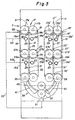
- Figure 3 is an alternative arrangement of the embodiment of Figure 1 and therefore the same reference numerals for similar elements as used in Figure 1 are used in Figure 3.
- the embodiment of Figure 3 differs from the embodiment of Figure 1 in that all of the processing assemblies 15, 15a, 15a' and 15' include nozzles 23.
- the operation of the embodiment of Figure 3, as well as the specifies of the elements of Figure 3 are the same as the described operation and corresponding elements of Figure 1.
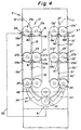
- Figure 4 is an alternative arrangement of the embodiment of Figure 1 and therefore the same reference numerals for similar elements as used in Figure 1 are used in Figure 4.
- the embodiment of Figure 4 differs from the embodiment of Figure 1 as well as the embodiment of Figure 3 in that none of the processing assemblies 15, 15a, 15a' and 15' include nozzles 23.
- the operation of the embodiment of Figure 4, as well as the specifies of the elements of Figure 4 are the same as the described operation and corresponding elements of Figure 1.
- the guide paths 21, 31, 21' and 31' as shown in Figures 3 and 4 can also include textured surfaces as illustrated in Figures 2A and 2B.
- each of the processing assemblies are arranged so as to define the processing path and also to minimize exposure of the photosensitive material being treated to air. Also, it is recognized that the application of fresh processing solution at the area of the exit of the photosensitive material from tank 7 is one example, and that fresh processing solution can be applied at the entry and exit of tank 7.
Landscapes
- Physics & Mathematics (AREA)
- General Physics & Mathematics (AREA)
- Photographic Processing Devices Using Wet Methods (AREA)
Applications Claiming Priority (2)
| Application Number | Priority Date | Filing Date | Title |
|---|---|---|---|
| US947817 | 1997-10-09 | ||
| US08/947,817 US5899594A (en) | 1997-10-09 | 1997-10-09 | Processing apparatus and method utilizing a tray assembly and a guide path arrangement |
Publications (2)
| Publication Number | Publication Date |
|---|---|
| EP0908773A2 true EP0908773A2 (fr) | 1999-04-14 |
| EP0908773A3 EP0908773A3 (fr) | 1999-06-16 |
Family
ID=25486834
Family Applications (1)
| Application Number | Title | Priority Date | Filing Date |
|---|---|---|---|
| EP98203254A Withdrawn EP0908773A3 (fr) | 1997-10-09 | 1998-09-28 | Système et méthode de traitement utilisant un assemblage de cuves et un arrangement de guidage |
Country Status (4)
| Country | Link |
|---|---|
| US (1) | US5899594A (fr) |
| EP (1) | EP0908773A3 (fr) |
| JP (1) | JPH11194469A (fr) |
| CN (1) | CN1214466A (fr) |
Families Citing this family (2)
| Publication number | Priority date | Publication date | Assignee | Title |
|---|---|---|---|---|
| GB0026949D0 (en) * | 2000-11-03 | 2000-12-20 | Eastman Kodak Co | Processing photographic material |
| ES2598004B1 (es) | 2015-06-24 | 2017-12-12 | Pablo IBAÑEZ RAZOLA | Máquina compacta híbrida digital-analógica de revelado |
Family Cites Families (9)
| Publication number | Priority date | Publication date | Assignee | Title |
|---|---|---|---|---|
| US3145637A (en) * | 1960-07-12 | 1964-08-25 | Gen Aniline & Film Corp | Diazotype development apparatus |
| US3318222A (en) * | 1964-06-08 | 1967-05-09 | Gen Aniline & Film Corp | Paper guiding and evaporation control in moist reproduction machines |
| HU188540B (en) * | 1983-12-23 | 1986-04-28 | Schneider,Laszlo,Hu | Phototechnological apparatus for continuous developement of phototechnological materials |
| EP0337174B1 (fr) * | 1988-04-11 | 1994-10-26 | Fuji Photo Film Co., Ltd. | Appareillage de développement de matériel photosensible |
| US5168296A (en) * | 1988-04-20 | 1992-12-01 | Fuji Photo Film Co., Ltd. | Method and apparatus for processing photosensitive material |
| US5311235A (en) * | 1992-03-02 | 1994-05-10 | Eastman Kodak Company | Driving mechanism for a photographic processing apparatus |
| US5309191A (en) * | 1992-03-02 | 1994-05-03 | Eastman Kodak Company | Recirculation, replenishment, refresh, recharge and backflush for a photographic processing apparatus |
| DE4239401A1 (de) * | 1992-11-24 | 1994-05-26 | Agfa Gevaert Ag | Vorrichtung und Verfahren zur schnellen Wässerung von fotografischem Material |
| US5669035A (en) * | 1995-08-30 | 1997-09-16 | Konica Corporation | Apparatus for processing a silver halide photosensitive material |
-
1997
- 1997-10-09 US US08/947,817 patent/US5899594A/en not_active Expired - Fee Related
-
1998
- 1998-09-28 EP EP98203254A patent/EP0908773A3/fr not_active Withdrawn
- 1998-10-08 JP JP10286789A patent/JPH11194469A/ja active Pending
- 1998-10-09 CN CN98120913.0A patent/CN1214466A/zh active Pending
Also Published As
| Publication number | Publication date |
|---|---|
| US5899594A (en) | 1999-05-04 |
| EP0908773A3 (fr) | 1999-06-16 |
| JPH11194469A (ja) | 1999-07-21 |
| CN1214466A (zh) | 1999-04-21 |
Similar Documents
| Publication | Publication Date | Title |
|---|---|---|
| US5923916A (en) | Processing assembly having a processing apparatus with an inclined processing path | |
| US5899594A (en) | Processing apparatus and method utilizing a tray assembly and a guide path arrangement | |
| US6012859A (en) | Processing apparatus and method for processing photosensitive material | |
| US5975774A (en) | Compact processing apparatus and method for processing photosensitive material | |
| US5903795A (en) | Photographic processor | |
| EP0762205A1 (fr) | Appareil de traitement pour matériau à l'halogénure d'argent sensible à la lumière | |
| US5822643A (en) | Photographic processor | |
| US6086270A (en) | Processing photographic material | |
| JPH0730379Y2 (ja) | 感光性平版印刷版用処理液塗布装置 | |
| JP3283096B2 (ja) | 感光材料処理装置 | |
| JPS62115450A (ja) | 自動現像装置 | |
| US5045874A (en) | Water distributor system for crossover assemblies in a film processor | |
| JP2822232B2 (ja) | 感光材料処理装置 | |
| JP3903107B2 (ja) | 感光材料現像処理装置 | |
| JP2832747B2 (ja) | 写真用自動現像機 | |
| JP3349266B2 (ja) | 感光材料処理装置 | |
| US6161968A (en) | Processing photographic material | |
| JP4143942B2 (ja) | 写真処理装置 | |
| EP0915378A2 (fr) | Traitement de matériau photographique | |
| EP0908775A2 (fr) | Traitement de matériau photographique | |
| JPH0132035Y2 (fr) | ||
| EP0908768A2 (fr) | Traitement de matériau photographique | |
| JPH09230559A (ja) | 感光材料処理装置 | |
| JPH10268496A (ja) | 写真感光材料用自動現像機及びプリンタープロセッサー | |
| JP2003280152A (ja) | 自動現像装置 |
Legal Events
| Date | Code | Title | Description |
|---|---|---|---|
| PUAI | Public reference made under article 153(3) epc to a published international application that has entered the european phase |
Free format text: ORIGINAL CODE: 0009012 |
|
| AK | Designated contracting states |
Kind code of ref document: A2 Designated state(s): CH DE FR GB IT LI |
|
| AX | Request for extension of the european patent |
Free format text: AL;LT;LV;MK;RO;SI |
|
| PUAL | Search report despatched |
Free format text: ORIGINAL CODE: 0009013 |
|
| AK | Designated contracting states |
Kind code of ref document: A3 Designated state(s): AT BE CH CY DE DK ES FI FR GB GR IE IT LI LU MC NL PT SE |
|
| AX | Request for extension of the european patent |
Free format text: AL;LT;LV;MK;RO;SI |
|
| RIC1 | Information provided on ipc code assigned before grant |
Free format text: 6G 03D 3/13 A, 6G 03D 5/06 B |
|
| 17P | Request for examination filed |
Effective date: 19991116 |
|
| AKX | Designation fees paid |
Free format text: CH DE FR GB IT LI |
|
| 17Q | First examination report despatched |
Effective date: 20030826 |
|
| STAA | Information on the status of an ep patent application or granted ep patent |
Free format text: STATUS: THE APPLICATION IS DEEMED TO BE WITHDRAWN |
|
| 18D | Application deemed to be withdrawn |
Effective date: 20040107 |