EP0911511A2 - Procédé d'injection de carburant dans la chambre de combustion d'un moteur auto-allumage par compression d'air - Google Patents
Procédé d'injection de carburant dans la chambre de combustion d'un moteur auto-allumage par compression d'air Download PDFInfo
- Publication number
- EP0911511A2 EP0911511A2 EP98111578A EP98111578A EP0911511A2 EP 0911511 A2 EP0911511 A2 EP 0911511A2 EP 98111578 A EP98111578 A EP 98111578A EP 98111578 A EP98111578 A EP 98111578A EP 0911511 A2 EP0911511 A2 EP 0911511A2
- Authority
- EP
- European Patent Office
- Prior art keywords
- injection
- post
- internal combustion
- combustion engine
- pressure
- Prior art date
- Legal status (The legal status is an assumption and is not a legal conclusion. Google has not performed a legal analysis and makes no representation as to the accuracy of the status listed.)
- Granted
Links
Images


Classifications
-
- F—MECHANICAL ENGINEERING; LIGHTING; HEATING; WEAPONS; BLASTING
- F02—COMBUSTION ENGINES; HOT-GAS OR COMBUSTION-PRODUCT ENGINE PLANTS
- F02M—SUPPLYING COMBUSTION ENGINES IN GENERAL WITH COMBUSTIBLE MIXTURES OR CONSTITUENTS THEREOF
- F02M45/00—Fuel-injection apparatus characterised by having a cyclic delivery of specific time/pressure or time/quantity relationship
- F02M45/02—Fuel-injection apparatus characterised by having a cyclic delivery of specific time/pressure or time/quantity relationship with each cyclic delivery being separated into two or more parts
-
- F—MECHANICAL ENGINEERING; LIGHTING; HEATING; WEAPONS; BLASTING
- F02—COMBUSTION ENGINES; HOT-GAS OR COMBUSTION-PRODUCT ENGINE PLANTS
- F02D—CONTROLLING COMBUSTION ENGINES
- F02D41/00—Electrical control of supply of combustible mixture or its constituents
- F02D41/30—Controlling fuel injection
- F02D41/38—Controlling fuel injection of the high pressure type
- F02D41/40—Controlling fuel injection of the high pressure type with means for controlling injection timing or duration
- F02D41/402—Multiple injections
-
- F—MECHANICAL ENGINEERING; LIGHTING; HEATING; WEAPONS; BLASTING
- F02—COMBUSTION ENGINES; HOT-GAS OR COMBUSTION-PRODUCT ENGINE PLANTS
- F02D—CONTROLLING COMBUSTION ENGINES
- F02D41/00—Electrical control of supply of combustible mixture or its constituents
- F02D41/30—Controlling fuel injection
- F02D41/38—Controlling fuel injection of the high pressure type
- F02D41/40—Controlling fuel injection of the high pressure type with means for controlling injection timing or duration
- F02D41/402—Multiple injections
- F02D41/405—Multiple injections with post injections
-
- F—MECHANICAL ENGINEERING; LIGHTING; HEATING; WEAPONS; BLASTING
- F02—COMBUSTION ENGINES; HOT-GAS OR COMBUSTION-PRODUCT ENGINE PLANTS
- F02M—SUPPLYING COMBUSTION ENGINES IN GENERAL WITH COMBUSTIBLE MIXTURES OR CONSTITUENTS THEREOF
- F02M63/00—Other fuel-injection apparatus having pertinent characteristics not provided for in groups F02M39/00 - F02M57/00 or F02M67/00; Details, component parts, or accessories of fuel-injection apparatus, not provided for in, or of interest apart from, the apparatus of groups F02M39/00 - F02M61/00 or F02M67/00; Combination of fuel pump with other devices, e.g. lubricating oil pump
- F02M63/02—Fuel-injection apparatus having several injectors fed by a common pumping element, or having several pumping elements feeding a common injector; Fuel-injection apparatus having provisions for cutting-out pumps, pumping elements, or injectors; Fuel-injection apparatus having provisions for variably interconnecting pumping elements and injectors alternatively
- F02M63/0225—Fuel-injection apparatus having a common rail feeding several injectors ; Means for varying pressure in common rails; Pumps feeding common rails
-
- F—MECHANICAL ENGINEERING; LIGHTING; HEATING; WEAPONS; BLASTING
- F01—MACHINES OR ENGINES IN GENERAL; ENGINE PLANTS IN GENERAL; STEAM ENGINES
- F01N—GAS-FLOW SILENCERS OR EXHAUST APPARATUS FOR MACHINES OR ENGINES IN GENERAL; GAS-FLOW SILENCERS OR EXHAUST APPARATUS FOR INTERNAL-COMBUSTION ENGINES
- F01N2430/00—Influencing exhaust purification, e.g. starting of catalytic reaction, filter regeneration, or the like, by controlling engine operating characteristics
- F01N2430/08—Influencing exhaust purification, e.g. starting of catalytic reaction, filter regeneration, or the like, by controlling engine operating characteristics by modifying ignition or injection timing
- F01N2430/085—Influencing exhaust purification, e.g. starting of catalytic reaction, filter regeneration, or the like, by controlling engine operating characteristics by modifying ignition or injection timing at least a part of the injection taking place during expansion or exhaust stroke
-
- F—MECHANICAL ENGINEERING; LIGHTING; HEATING; WEAPONS; BLASTING
- F02—COMBUSTION ENGINES; HOT-GAS OR COMBUSTION-PRODUCT ENGINE PLANTS
- F02B—INTERNAL-COMBUSTION PISTON ENGINES; COMBUSTION ENGINES IN GENERAL
- F02B3/00—Engines characterised by air compression and subsequent fuel addition
- F02B3/06—Engines characterised by air compression and subsequent fuel addition with compression ignition
-
- Y—GENERAL TAGGING OF NEW TECHNOLOGICAL DEVELOPMENTS; GENERAL TAGGING OF CROSS-SECTIONAL TECHNOLOGIES SPANNING OVER SEVERAL SECTIONS OF THE IPC; TECHNICAL SUBJECTS COVERED BY FORMER USPC CROSS-REFERENCE ART COLLECTIONS [XRACs] AND DIGESTS
- Y02—TECHNOLOGIES OR APPLICATIONS FOR MITIGATION OR ADAPTATION AGAINST CLIMATE CHANGE
- Y02T—CLIMATE CHANGE MITIGATION TECHNOLOGIES RELATED TO TRANSPORTATION
- Y02T10/00—Road transport of goods or passengers
- Y02T10/10—Internal combustion engine [ICE] based vehicles
- Y02T10/40—Engine management systems
Definitions
- the invention is based on a method according to the preamble of claim 1.
- a method which is known from EP-A1-0 621 400
- post-injection of fuel after the main injection in connection with an exhaust gas aftertreatment device is proposed with the aim of reducing the NO x components in the exhaust gas.
- a so-called DENOX catalytic converter is provided as the aftertreatment device, which, in conjunction with highly reactive hydrocarbon fragments in the exhaust gas, is intended to reduce the NO x components. This reduction is particularly efficient only if unburned hydrocarbons still get into the catalyst.
- a late post-injection is used in particular, which is injected 80 ° crank angle after top dead center, the fuel not burning but being optimally processed due to the residual heat by being vaporized or cracked.
- diesel engines In addition to the goal of reducing NO x emissions, diesel engines also have the task of keeping the soot components in the exhaust gas low with regard to exhaust gas emissions. The known method does not provide any starting points for this. In addition to the goal of reducing soot emissions, there is also the task of keeping the specific fuel consumption and noise low in order to optimize a diesel injection system.
- inventive method according to the characterizing part of patent claim 1 achieves a considerable reduction in the development of soot in the exhaust gas for given operating parameters. There is also the possibility of reducing fuel consumption while maintaining certain NO x values in the exhaust gas.
- the coupled to the end of the main injection i.e. yourself after the injection process for the Main injection immediately follows, you get one divided injection that is extremely effective in terms of is the reduction of soot emissions. It is whole essential that the fuel injection at the Post-injection takes place under the same injection pressure as the injection at the main injection. This distinguishes this injection above all from that unwanted post-injection at low injection pressure.
- an injection system which one Provides high pressure fuel storage that is constantly supplied by a high pressure pump and its Fuel from electrically controlled Fuel injectors is removed fuel injection according to the invention with main and Post-injection possible.
- the high fuel pressure also at the post-injection ensures optimal preparation of the introduced fuel that continues to burn participates.
- the main and post-injection together make up the Total injection quantity per work cycle of the internal combustion engine dar according to claim 2.
- the post-injection as soon as possible after the end of the Main injection. It is thus firmly at the end of the Main injection coupled and this is the only way favorable effectiveness of the post-injection, the one again incipient combustion process initiated under pressure and Temperature conditions of the combustion chamber, which for a Fuel combustion in the work cycle are required. With this new injection, the turnover of the amount of fuel already introduced together with the Post-injection started again.
- the amount of post-injection changes depending on the operating parameter of the internal combustion engine and is controlled according to claim 5 by an electrical control device which ensures that the post-injection takes place in the desired connection to the main injection and in the required amount.
- control values for the control device are stored in a map, which was determined in an optimization process and is specific to the internal combustion engine.
- the post-injection takes place only after a lower load point has been exceeded, below which no particular effectiveness of the post-injection can be demonstrated.
- the amount of post-injection is also optimized in relation to the load as part of the map determination. It may be the case that the amount of fuel to be injected must increase or decrease with increasing load depending on the operating speed in order to achieve an optimized reduction in soot emissions.
- control values for the control device are determined in the characteristic diagram with the aid of sensors, the opening and closing times of the injection valves at the various operating points being recorded to control the start of the post-injection, in particular with the aid of sensors attached to the injection valves. This is done by observing the soot emission in the exhaust gas and optimizing the post-injection quantity.
- the optimization is also carried out by varying the injection pressure that is available through the fuel of the high-pressure fuel accumulator. This optimization has a particularly positive effect in terms of a reduction in NO x components and a reduction in fuel consumption.
- FIG. 1 shows a fuel injection system in a schematic representation, on which the object of the invention is realized
- FIG. 2a and FIG. 2b the representation of the relationship between NO x and soot emission and the specific fuel consumption at different injection pressures of the high-pressure fuel accumulator (rail)
- FIGS. 3a and 3b the effect of the post-injection according to the invention on the parameters blackening number SZ (soot content), NO x and specific fuel consumption in relation to the operation of the internal combustion engine without post-injection, plotted at different injection start times
- FIGS. 1 shows a fuel injection system in a schematic representation, on which the object of the invention is realized
- FIG. 2a and FIG. 2b the representation of the relationship between NO x and soot emission and the specific fuel consumption at different injection pressures of the high-pressure fuel accumulator (rail)
- FIGS. 3a and 3b the effect of the post-injection according to the invention on the parameters blackening number SZ (soot content), NO x
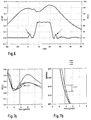
- FIG. 5 shows the course of the injection using the H ubes the needle of a fuel injection valve during a main injection and a subsequent post-injection in relation to the pressure which arises in the combustion chamber
- FIG. 6 shows a representation analogous to FIG. 5 but with additional pre-injection and FIGS.
- 7a and 7b show the relationship between the density ratio, NO x emission and specific fuel consumption , plotted over different injection start times in comparison with operation of the internal combustion engine without pre-injection and post-injection, with pre-injection but without post-injection and with pre-injection (VE) and with post-injection (NE).
- FIG. 1 shows a high-pressure fuel reservoir 1 (rail) shown by a high pressure pump 2 from a Fuel tank 3 is supplied with fuel.
- a high pressure fuel accumulator On the high pressure fuel accumulator are several Fuel injectors 5, 5 '5' 'of the same type Pressure lines 6, 6 ', 6' 'connected to the High pressure fuel injectors supply.
- the high-pressure fuel reservoir is thereby the high pressure pump 2 if possible only the amount of fuel fed, which then also from the fuel injection valves is removed. This can be the delivery rate of the high pressure amount 3 are controlled depending on the pressure (rail pressure) in the High-pressure fuel accumulator (rail).
- a pressure sensor 7 To capture the Pressure, a pressure sensor 7 is provided, the Output values are fed to a control device 8.
- Map 9 can be stored and controls accordingly the deviation from the nominal value the high pressure delivery rate of the High pressure pump 2.
- Influence on a Throttle body 10 taken in the supply line to the high pressure pump be or an intervention in the high pressure pump itself be made such that e.g. at with constant stroke pump piston promoting the delivery duration with the help of Controllers is controlled.
- Such control elements can Inclined edge controls that are electrically operated be or solenoid valves.
- the Feed pump 2 with constant or speed-dependent Promote the delivery rate and thereby generate a pressure that is above the need goes beyond.
- a pressure control valve 12 in the bypass to the high pressure pump 2 ' the pressure is electrically controlled corrected in the high-pressure fuel reservoir 1.
- pressure control valves 14 are provided which are then based on a feedforward control the side of the feed pump 2 with the aid of a throttle 11 or a feed pump 2 'with pressure control valve 2 a Fine control of high fuel pressure in the Carry out high-pressure fuel accumulator.
- This high pressure is essentially the injection pressure that at Fuel injector is effective.
- the Fuel injection valves are of the same type overall, the fuel injector 5 '' is closer to them shown.
- Electric fuel injectors controlled type such as this, which is preferably used for Injection from a common rail, the High-pressure fuel accumulator 1, preferably serve one with the injection needle not shown connected piston 16 which in a cylinder 17 of the Fuel injection valve housing 18 a control room 19th limited on the face.
- This control room is constantly over a throttle 20 with the high-pressure fuel accumulator connected and is also via an electrically controlled Valve 21 can be relieved via a relief line 22.
- a such valve which is to be referred to as a control valve, can be electromagnetic but also by a piezo actuator be operated. The latter offers the advantage of one very high control speed, which in connection with that small hydraulic space of the control room 19 a very causes the fuel injector to switch quickly.
- control valve 21 is a 2/2 valve
- injection valves are also electric controlled type known, in which in the supply line between High-pressure fuel accumulator and injection point on Electrically controlled fuel injector Passage actuators are provided.
- fuel injector is the High fuel pressure constantly on a pressure shoulder 23 of the Nozzle needle 24, which opens when the control room 19th is relieved under the influence of the pressure shoulder applied opening force.
- Such valves are already there known and need not be described in detail.
- the fuel injectors can now be operated through the electrical control device 8 in the constantly pending high fuel injection pressure quickly even for the shortest Fuel injection quantities are switched.
- the Control device 8 has the function of a desired pressure in the high-pressure fuel reservoir to be observed, which is essentially constant, but which is ultimately also in relation to certain modes of operation the associated internal combustion engine, not shown here can be specifically changed. Basically, the values of the fuel pressure to be set in the map 9 saved and can be there if certain Operating parameters called up with variable values become. The essentially constant setting value becomes thereby, as already said, with the measured value of the pressure sensor 7 compared and it is according to the comparison result via the fuel supply via the high-pressure fuel pump intervened effectively.
- Figure 2a shows a family of curves with constant injection pressures. The course of the curve is varied by the start of spraying and represents the relationship between the soot component and NO x component in the exhaust gas. It can be seen that the lower the NO x component in the exhaust gas, the higher the soot content. Conversely, the soot content decreases with increasing NO x content as the start of spraying changes. It can also be seen from curve 2a that lower soot and NO x values are achieved with increasing fuel injection pressure. However, if one looks at the specific fuel consumption, it can be seen from FIG. 2b that, initially, the specific fuel consumption also becomes lower when the NO x emission increases and vice versa.
- the main injection is now one Post-injection attached as shown in the diagram 5 can be seen.
- Needle stroke of the respective fuel injection valve applied and you can see the course on the bottom line a main injection that is at about 5 ° crankshaft angle starts and ends at 25 ° crankshaft angle, namely, when the needle stroke has reached 0.0 again.
- a main injection that is at about 5 ° crankshaft angle starts and ends at 25 ° crankshaft angle, namely, when the needle stroke has reached 0.0 again.
- Valve opened again with a small needle stroke the is indicated by the arrow post-injection and then is finished again at about 28 ° crankshaft angle.
- Main injection and Post-injections are made from one and the same Fuel tank under the same high Fuel injection pressure, this post-injection even with a smaller needle stroke than a fully fledged one controlled injection is to be considered, the whole clearly from unwanted post-injection at low Differentiate fuel injection pressure.
- post-injections are also under the influence of reflective pressure waves in pressure lines between High pressure source and injector opening when the opening pressure of the Fuel injector is exceeded. This one then upcoming pressure does not correspond in any way to the actual one Fuel injection pressure, which is used for the main injection or required fuel preparation is necessary.
- Electrically controlled valves, especially valves that work with a piezo actuator are able to Shortest opening times for post-injection exactly to make it manageable.
- FIGS. 3a and 3b The effect of the post-injection can be explained with reference to FIGS. 3a and 3b.
- curves are shown in the case of a changing start of spraying in relation to the blackening number and the NO x emission or the specific fuel consumption for the NO x emission, specifically for operation of the internal combustion engine with post-injection and without post-injection.
- FIG. 3a it can be seen that the curves diverge with increasing start of spray in the direction of early and increasing NO x content. If, for example, the start of injection of + 2 ° crankshaft angle results in a significant reduction in the soot content in the exhaust gas if the combustion takes place with post-injection. On the other hand, if one compares the effect of this measure on the specific fuel consumption according to FIG.
- FIGS. 3a and 3b it can be seen that there is no deterioration here, but that the curves with post-injection and without post-injection run congruently with one another.
- the values shown in FIGS. 3a and 3b were determined at an engine speed of 1400 rpm and at 75% load.
- the injection pressure was 900 bar with a post-injection quantity of approx. 12 mg / stroke.
- the curves according to FIGS. 2a and 2b were also determined at 1400 rpm, but at 50% load.
- the total injection quantity is also the post-injection quantity effective drive.
- This post-injection quantity is also the target fully implement unlike others Post-injection processes that only serve a catalyst the HC emission necessary for its work to provide and this on operating temperature to keep.
- FIG. 4a shows this relationship, taking advantage of the fact that, according to FIG. 2b, the specific consumption also decreases as the fuel injection pressure decreases. Of course, this does not apply without restriction, but within the framework of the basic injection pressure at all. If one compares FIG. 2a, an increase in the soot with a decreasing fuel injection pressure can be accepted if the soot figure has made a profit by the post-injection. 4a shows two curves, one with post-injection at 850 bar injection pressure and one without post-injection at 900 bar injection pressure (rail pressure).
- a total of 3 curves with changing start of injection are plotted here, a first curve which, as shown in the legend above FIG. 7b, results from the operation without pre-injection (VE) and without post-injection (NE), a second curve that results results in the operation with pre-injection and without post-injection and finally a third curve which results from the operation with pre-injection and with post-injection.
- the other parameters such as the fuel injection pressure, which in turn is kept here at 900 bar with 5 mg pre-injection quantity per stroke and 12 mg post-injection quantity per stroke, the curves are essentially congruent in the lower NO x ranges.
- the post-injection which is directly coupled to the main injection, is also variable in terms of quantity. It is essential that the post-injection quantity complies with certain ranges, which in particular can also be determined empirically. It has been shown that with post-injection quantities ⁇ 5 mg / stroke, no noticeable improvements in the density ratio can be achieved. On the other hand, if the post-injection quantity is increased beyond 20 mg / stroke, the HC emission increases considerably. It is also harmful if the direct coupling of the post-injection to the main injection is not observed. With increasing distance between the start of injection of the post-injection and the main injection, a high HC emission sets in again, which was previously also used to make downstream exhaust gas treatment devices effective in the reducing sense of NO x components.
- the information about the Operating field of the internal combustion engine required Injection processes recorded with the help of needle stroke sensors and entered appropriate control values to control post-injection are required.
- the control of the injection pressure can be optimized in order in particular on the desired emissions and Consumption values to come. It has been shown that only from a certain load on the internal combustion engine Post-injection is effective in the sense of their use.
- the limit can be measured by recording the emission values and to control the post-injection in the map can be entered.
- the limit lies in a range between 10% and 25% of full load, i.e. it is only from larger values make a sensible post-injection. With increasing The amount of post-injection is then optimized varies in relation to the respective operating point.
Landscapes
- Engineering & Computer Science (AREA)
- Chemical & Material Sciences (AREA)
- Combustion & Propulsion (AREA)
- Mechanical Engineering (AREA)
- General Engineering & Computer Science (AREA)
- Electrical Control Of Air Or Fuel Supplied To Internal-Combustion Engine (AREA)
- Fuel-Injection Apparatus (AREA)
Applications Claiming Priority (2)
| Application Number | Priority Date | Filing Date | Title |
|---|---|---|---|
| DE19747231A DE19747231A1 (de) | 1997-10-25 | 1997-10-25 | Verfahren zur Einspritzung von Kraftstoff in die Brennräume einer luftverdichtenden, selbstzündenden Brennkraftmaschine |
| DE19747231 | 1997-10-25 |
Publications (3)
| Publication Number | Publication Date |
|---|---|
| EP0911511A2 true EP0911511A2 (fr) | 1999-04-28 |
| EP0911511A3 EP0911511A3 (fr) | 2002-10-30 |
| EP0911511B1 EP0911511B1 (fr) | 2004-09-15 |
Family
ID=7846634
Family Applications (1)
| Application Number | Title | Priority Date | Filing Date |
|---|---|---|---|
| EP98111578A Expired - Lifetime EP0911511B1 (fr) | 1997-10-25 | 1998-06-24 | Procédé d'injection de carburant dans la chambre de combustion d'un moteur auto-allumage par compression d'air |
Country Status (4)
| Country | Link |
|---|---|
| US (1) | US6073608A (fr) |
| EP (1) | EP0911511B1 (fr) |
| JP (1) | JPH11200933A (fr) |
| DE (2) | DE19747231A1 (fr) |
Cited By (2)
| Publication number | Priority date | Publication date | Assignee | Title |
|---|---|---|---|---|
| US6712036B1 (en) | 1999-09-29 | 2004-03-30 | Ab Volvo | Method of controlling the fuel injection in an internal combustion engine |
| WO2009033597A1 (fr) * | 2007-09-07 | 2009-03-19 | Testo Ag | Procédé et dispositif de mesure d'émissions sur des moteurs |
Families Citing this family (35)
| Publication number | Priority date | Publication date | Assignee | Title |
|---|---|---|---|---|
| EP1064457B1 (fr) * | 1998-03-16 | 2002-06-12 | Siemens Aktiengesellschaft | Procede pour determiner le temps d'injection dans un moteur a combustion interne a injection directe |
| DE10000398A1 (de) * | 2000-01-07 | 2001-07-12 | Volkswagen Ag | Verfahren zur Ermittlung von Einspritzparametern einer Dieselbrennkraftmaschine |
| US6439194B2 (en) * | 2000-01-31 | 2002-08-27 | International Engine Intellectual Property Company, L.L.C. | Modified lead injector |
| JP4568991B2 (ja) * | 2000-02-23 | 2010-10-27 | マツダ株式会社 | エンジンの排気浄化装置および燃料噴射時期の設定方法 |
| JP3775498B2 (ja) * | 2000-03-31 | 2006-05-17 | 三菱ふそうトラック・バス株式会社 | 蓄圧式燃料噴射装置 |
| DE10029502A1 (de) * | 2000-06-21 | 2002-01-31 | Daimler Chrysler Ag | Beschleunigter Aufbau des Ladedrucks durch ein mehrstufiges Brennverfahren für Dieselmotoren |
| DE10031579A1 (de) * | 2000-06-29 | 2002-01-17 | Bosch Gmbh Robert | Druckgesteuerter Injektor mit Vario-Register-Einspritzdüse |
| US6467452B1 (en) * | 2000-07-13 | 2002-10-22 | Caterpillar Inc | Method and apparatus for delivering multiple fuel injections to the cylinder of an internal combustion engine |
| JP4588971B2 (ja) * | 2000-07-18 | 2010-12-01 | ローベルト ボツシユ ゲゼルシヤフト ミツト ベシユレンクテル ハフツング | 内燃機関を制御するための方法及び装置 |
| JP2002038990A (ja) | 2000-07-26 | 2002-02-06 | Mazda Motor Corp | ディーゼルエンジンの燃料噴射装置 |
| DE10040117B4 (de) | 2000-08-17 | 2013-02-21 | Daimler Ag | Verfahren zum Betrieb eines Dieselmotors |
| JP4505702B2 (ja) * | 2000-12-01 | 2010-07-21 | マツダ株式会社 | ディーゼルエンジンの燃料噴射制御装置 |
| JP4587012B2 (ja) * | 2000-12-06 | 2010-11-24 | マツダ株式会社 | ディーゼルエンジンの燃料噴射制御装置 |
| JP4506001B2 (ja) * | 2001-02-14 | 2010-07-21 | マツダ株式会社 | ディーゼルエンジンの燃料噴射装置 |
| DE10112702A1 (de) * | 2001-03-16 | 2002-10-02 | Bosch Gmbh Robert | Verfahren zum Betreiben einer Brennkraftmaschine mit einem Kraftstoffzumesssystem |
| SE522624C2 (sv) * | 2001-03-29 | 2004-02-24 | Volvo Teknisk Utveckling Ab | Förfarande för att styra insprutningen av en fluid i en förbränningsmotor |
| JP3987298B2 (ja) * | 2001-04-05 | 2007-10-03 | 三菱ふそうトラック・バス株式会社 | 蓄圧式燃料噴射装置 |
| US6595189B2 (en) * | 2001-08-10 | 2003-07-22 | Caterpillar Inc | Method of reducing noise in a mechanically actuated fuel injection system and engine using same |
| JP2003065115A (ja) * | 2001-08-22 | 2003-03-05 | Mazda Motor Corp | エンジンの排気浄化装置及びそのコンピュータ・プログラム |
| DE10145580A1 (de) | 2001-09-15 | 2003-04-17 | Bosch Gmbh Robert | Verfahren zum Vermeiden einer Spritzlochinnenverkokung von Spritzlöchern eines Mehrloch-Einspritzventils |
| US6651613B2 (en) * | 2001-11-30 | 2003-11-25 | Caterpillar Inc | Method and system of fuel injector operation |
| FR2837241B1 (fr) * | 2002-03-13 | 2006-06-09 | Renault | Procede de regeneration d'un filtre a particules |
| KR100476198B1 (ko) * | 2002-05-09 | 2005-03-16 | 현대자동차주식회사 | 디젤 커먼 레일 분사 시스템의 후분사 연료량 제어방법 |
| KR100432035B1 (ko) * | 2002-06-18 | 2004-05-17 | 현대자동차주식회사 | 커먼 레일 연료 분사 장치에서의 멀티 분사 제어 방법 |
| DE10308789A1 (de) | 2003-02-28 | 2004-09-16 | Man B & W Diesel Ag | Verfahren zur Optimierung des Arbeits- und Brennverfahrens eines Dieselmotors |
| US20050224044A1 (en) * | 2004-04-08 | 2005-10-13 | Stojkovic Boris D | Injection strategy for low noise and soot combustion |
| JP4225240B2 (ja) * | 2004-04-28 | 2009-02-18 | トヨタ自動車株式会社 | 内燃機関の燃料供給装置 |
| JP2007187149A (ja) * | 2005-12-13 | 2007-07-26 | Nissan Motor Co Ltd | エンジンの燃料噴射制御方法及び燃料噴射制御装置 |
| JP4420097B2 (ja) * | 2007-10-02 | 2010-02-24 | 株式会社デンソー | 噴射異常検出装置及び燃料噴射システム |
| JP5115464B2 (ja) * | 2008-12-15 | 2013-01-09 | トヨタ自動車株式会社 | 内燃機関の制御パラメータの設定装置 |
| JP5056966B2 (ja) * | 2011-03-10 | 2012-10-24 | 株式会社豊田自動織機 | 燃焼制御装置 |
| US20130104848A1 (en) | 2011-10-27 | 2013-05-02 | Achates Power, Inc. | Fuel Injection Strategies in Opposed-Piston Engines with Multiple Fuel Injectors |
| JP6217398B2 (ja) * | 2014-01-09 | 2017-10-25 | マツダ株式会社 | ディーゼルエンジンの燃料噴射制御装置 |
| CN113775452B (zh) * | 2020-06-09 | 2022-08-02 | 中国航发商用航空发动机有限责任公司 | 一种发动机燃油分配装置 |
| DE102021001288A1 (de) | 2021-03-10 | 2022-09-15 | Mercedes-Benz Group AG | Verfahren zum Betreiben einer Verbrennungskraftmaschine eines Kraftfahrzeugs |
Family Cites Families (10)
| Publication number | Priority date | Publication date | Assignee | Title |
|---|---|---|---|---|
| JP2578012Y2 (ja) * | 1989-07-20 | 1998-08-06 | 三菱自動車工業株式会社 | 燃料噴射装置 |
| EP0621400B1 (fr) * | 1993-04-23 | 1999-03-31 | Daimler-Benz Aktiengesellschaft | Moteur à combustion interne à injection et à compression d'air avec un dispositif pout traiter les gaz d'échappement à fin de réduire les oxides azoté |
| DE69430596T2 (de) * | 1993-12-28 | 2002-11-14 | Hitachi Ltd | Verfahren und Vorrichtung zur Steuerung einer Brennkraftmaschine |
| JPH08100739A (ja) * | 1994-10-04 | 1996-04-16 | Isuzu Motors Ltd | ディーゼル機関用燃料噴射ポンプ |
| JPH08261092A (ja) * | 1995-03-22 | 1996-10-08 | Isuzu Motors Ltd | インジェクタ |
| JP3671455B2 (ja) * | 1995-04-28 | 2005-07-13 | 株式会社デンソー | 内燃機関の排気浄化装置 |
| ES2135815T3 (es) * | 1995-05-03 | 1999-11-01 | Daimler Chrysler Ag | Tobera de inyeccion. |
| JPH09158810A (ja) * | 1995-10-02 | 1997-06-17 | Hino Motors Ltd | ディーゼルエンジン |
| JPH09126031A (ja) * | 1995-10-31 | 1997-05-13 | Isuzu Motors Ltd | ディーゼルエンジンの燃料噴射方法 |
| US5890459A (en) * | 1997-09-12 | 1999-04-06 | Southwest Research Institute | System and method for a dual fuel, direct injection combustion engine |
-
1997
- 1997-10-25 DE DE19747231A patent/DE19747231A1/de not_active Withdrawn
-
1998
- 1998-06-24 DE DE59811943T patent/DE59811943D1/de not_active Expired - Lifetime
- 1998-06-24 EP EP98111578A patent/EP0911511B1/fr not_active Expired - Lifetime
- 1998-10-19 US US09/174,546 patent/US6073608A/en not_active Expired - Lifetime
- 1998-10-26 JP JP10303859A patent/JPH11200933A/ja active Pending
Cited By (4)
| Publication number | Priority date | Publication date | Assignee | Title |
|---|---|---|---|---|
| US6712036B1 (en) | 1999-09-29 | 2004-03-30 | Ab Volvo | Method of controlling the fuel injection in an internal combustion engine |
| US6820587B1 (en) | 1999-09-29 | 2004-11-23 | Ab Volvo | Method for controlling a combustion process in a combustion engine |
| WO2009033597A1 (fr) * | 2007-09-07 | 2009-03-19 | Testo Ag | Procédé et dispositif de mesure d'émissions sur des moteurs |
| US8527179B2 (en) | 2007-09-07 | 2013-09-03 | Testo Ag | Method and device for measuring the emissions of engines |
Also Published As
| Publication number | Publication date |
|---|---|
| JPH11200933A (ja) | 1999-07-27 |
| EP0911511A3 (fr) | 2002-10-30 |
| EP0911511B1 (fr) | 2004-09-15 |
| DE19747231A1 (de) | 1999-04-29 |
| DE59811943D1 (de) | 2004-10-21 |
| US6073608A (en) | 2000-06-13 |
Similar Documents
| Publication | Publication Date | Title |
|---|---|---|
| EP0911511B1 (fr) | Procédé d'injection de carburant dans la chambre de combustion d'un moteur auto-allumage par compression d'air | |
| DE19610277C2 (de) | Nach dem Dieselverfahren arbeitende Hubkolbenbrennkraftmaschine mit Einlaßventil-Schließzeitpunkteinstellung | |
| DE19616555C2 (de) | Dieselmotor | |
| AT402432B (de) | Brennkraftmaschine | |
| DE10064055A1 (de) | Steuervorrichtung für Hochdruck-Kraftstoffpumpe und für Motor mit Direkteinspritzung | |
| DE10221165A1 (de) | Nacheinspritzungen während kalten Betriebes | |
| DE102007013119A1 (de) | Einspritzverfahren und zugehörige Verbrennungskraftmaschine | |
| DE112011101619T5 (de) | Dieselmotor für Automobil, Steuervorrichtung und Steuerverfahren | |
| WO1997011269A1 (fr) | Procede et dispositif de commande d'un moteur a combustion interne | |
| WO2007065573A1 (fr) | Procede de regulation d'un moteur a combustion interne, notamment d'un moteur a combustion interne a autoallumage | |
| EP1567760B1 (fr) | Procede pour commander un moteur a combustion interne a injection directe de carburant | |
| EP1581725B1 (fr) | Procede d'utilisation d'un moteur a combustion interne | |
| DE102016010309A1 (de) | Direkteinspritzender Verbrennungsmotor, Steuervorrichtung für einen derartigen Motor, Verfahren zum Steuern eines Motors und Computerprogrammprodukt | |
| DE102009017743A1 (de) | Steuerung für einen Dieselmotor nach dem Start | |
| DE10350798B4 (de) | Verfahren zum Betrieb einer Brennkraftmaschine | |
| EP1703112B1 (fr) | Procédé de chauffage d'un catalyseur d'un moteur à combustion interne | |
| DE10327845A1 (de) | Verfahren zur Verwendung von mehreren Brennstoffeinspritzungen zur Reduzierung von Motoremissionen im Leerlauf | |
| WO2009010280A2 (fr) | Procédé et dispositif de détermination dynamique d'un segment pour une plage angulaire à l'intérieur de laquelle une injection de carburant peut être réalisée dans un moteur à combustion interne | |
| EP2831400B1 (fr) | Procédé pour faire fonctionner un moteur à combustion interne | |
| EP0561740B1 (fr) | Méthode d'opération d'un moteur Diesel et ce moteur Diesel | |
| DE102012022156B4 (de) | Verfahren zur Kraftstoffeinspritzung in einen Dieselmotor sowie Steuereinrichtung | |
| EP1296053B1 (fr) | Procédé d'injection directe de combustible sous forme de deux injections ayant des angles d'injection différents et dispositif de commande d'injection | |
| EP1999355B1 (fr) | Procede et dispositif d'utilisation d'un moteur a combustion interne | |
| DE102016010310B4 (de) | Direkteinspritzender Verbrennungsmotor, Steuervorrichtung für einen derartigen Motor, Verfahren zum Steuern eines Motors und Computerprogrammprodukt | |
| EP1639255B1 (fr) | Procede de fonctionnement d'un moteur a combustion interne a injection directe et moteur a combustion a injection directe |
Legal Events
| Date | Code | Title | Description |
|---|---|---|---|
| PUAI | Public reference made under article 153(3) epc to a published international application that has entered the european phase |
Free format text: ORIGINAL CODE: 0009012 |
|
| AK | Designated contracting states |
Kind code of ref document: A2 Designated state(s): AT BE CH CY DE DK ES FI FR GB GR IE IT LI LU MC NL PT SE |
|
| AX | Request for extension of the european patent |
Free format text: AL;LT;LV;MK;RO;SI |
|
| PUAL | Search report despatched |
Free format text: ORIGINAL CODE: 0009013 |
|
| AK | Designated contracting states |
Kind code of ref document: A3 Designated state(s): AT BE CH CY DE DK ES FI FR GB GR IE IT LI LU MC NL PT SE |
|
| AX | Request for extension of the european patent |
Free format text: AL;LT;LV;MK;RO;SI |
|
| RIC1 | Information provided on ipc code assigned before grant |
Free format text: 7F 02M 45/02 A, 7F 01N 3/20 B, 7F 02M 63/02 B, 7F 02D 41/40 B |
|
| 17P | Request for examination filed |
Effective date: 20030502 |
|
| AKX | Designation fees paid |
Designated state(s): DE FR GB |
|
| 17Q | First examination report despatched |
Effective date: 20031006 |
|
| GRAP | Despatch of communication of intention to grant a patent |
Free format text: ORIGINAL CODE: EPIDOSNIGR1 |
|
| GRAS | Grant fee paid |
Free format text: ORIGINAL CODE: EPIDOSNIGR3 |
|
| GRAA | (expected) grant |
Free format text: ORIGINAL CODE: 0009210 |
|
| AK | Designated contracting states |
Kind code of ref document: B1 Designated state(s): DE FR GB |
|
| REG | Reference to a national code |
Ref country code: GB Ref legal event code: FG4D Free format text: NOT ENGLISH |
|
| REG | Reference to a national code |
Ref country code: IE Ref legal event code: FG4D Free format text: GERMAN |
|
| REF | Corresponds to: |
Ref document number: 59811943 Country of ref document: DE Date of ref document: 20041021 Kind code of ref document: P |
|
| GBT | Gb: translation of ep patent filed (gb section 77(6)(a)/1977) |
Effective date: 20050126 |
|
| REG | Reference to a national code |
Ref country code: IE Ref legal event code: FD4D |
|
| PLBE | No opposition filed within time limit |
Free format text: ORIGINAL CODE: 0009261 |
|
| STAA | Information on the status of an ep patent application or granted ep patent |
Free format text: STATUS: NO OPPOSITION FILED WITHIN TIME LIMIT |
|
| ET | Fr: translation filed | ||
| 26N | No opposition filed |
Effective date: 20050616 |
|
| PGFP | Annual fee paid to national office [announced via postgrant information from national office to epo] |
Ref country code: GB Payment date: 20130620 Year of fee payment: 16 |
|
| PGFP | Annual fee paid to national office [announced via postgrant information from national office to epo] |
Ref country code: FR Payment date: 20130703 Year of fee payment: 16 |
|
| GBPC | Gb: european patent ceased through non-payment of renewal fee |
Effective date: 20140624 |
|
| REG | Reference to a national code |
Ref country code: FR Ref legal event code: ST Effective date: 20150227 |
|
| PG25 | Lapsed in a contracting state [announced via postgrant information from national office to epo] |
Ref country code: FR Free format text: LAPSE BECAUSE OF NON-PAYMENT OF DUE FEES Effective date: 20140630 Ref country code: GB Free format text: LAPSE BECAUSE OF NON-PAYMENT OF DUE FEES Effective date: 20140624 |
|
| PGFP | Annual fee paid to national office [announced via postgrant information from national office to epo] |
Ref country code: DE Payment date: 20150804 Year of fee payment: 18 |
|
| REG | Reference to a national code |
Ref country code: DE Ref legal event code: R119 Ref document number: 59811943 Country of ref document: DE |
|
| PG25 | Lapsed in a contracting state [announced via postgrant information from national office to epo] |
Ref country code: DE Free format text: LAPSE BECAUSE OF NON-PAYMENT OF DUE FEES Effective date: 20170103 |