EP0912044A2 - Amélioration adaptive de la netteté pour un moniteur à balayage multifréquentiel - Google Patents
Amélioration adaptive de la netteté pour un moniteur à balayage multifréquentiel Download PDFInfo
- Publication number
- EP0912044A2 EP0912044A2 EP98308781A EP98308781A EP0912044A2 EP 0912044 A2 EP0912044 A2 EP 0912044A2 EP 98308781 A EP98308781 A EP 98308781A EP 98308781 A EP98308781 A EP 98308781A EP 0912044 A2 EP0912044 A2 EP 0912044A2
- Authority
- EP
- European Patent Office
- Prior art keywords
- signal
- frequency
- sharpness
- input
- sharpness enhancement
- Prior art date
- Legal status (The legal status is an assumption and is not a legal conclusion. Google has not performed a legal analysis and makes no representation as to the accuracy of the status listed.)
- Withdrawn
Links
Images



Classifications
-
- G—PHYSICS
- G06—COMPUTING OR CALCULATING; COUNTING
- G06F—ELECTRIC DIGITAL DATA PROCESSING
- G06F3/00—Input arrangements for transferring data to be processed into a form capable of being handled by the computer; Output arrangements for transferring data from processing unit to output unit, e.g. interface arrangements
- G06F3/14—Digital output to display device ; Cooperation and interconnection of the display device with other functional units
- G06F3/153—Digital output to display device ; Cooperation and interconnection of the display device with other functional units using cathode-ray tubes
-
- H—ELECTRICITY
- H04—ELECTRIC COMMUNICATION TECHNIQUE
- H04N—PICTORIAL COMMUNICATION, e.g. TELEVISION
- H04N5/00—Details of television systems
- H04N5/14—Picture signal circuitry for video frequency region
- H04N5/20—Circuitry for controlling amplitude response
- H04N5/205—Circuitry for controlling amplitude response for correcting amplitude versus frequency characteristic
- H04N5/208—Circuitry for controlling amplitude response for correcting amplitude versus frequency characteristic for compensating for attenuation of high frequency components, e.g. crispening, aperture distortion correction
-
- G—PHYSICS
- G09—EDUCATION; CRYPTOGRAPHY; DISPLAY; ADVERTISING; SEALS
- G09G—ARRANGEMENTS OR CIRCUITS FOR CONTROL OF INDICATING DEVICES USING STATIC MEANS TO PRESENT VARIABLE INFORMATION
- G09G1/00—Control arrangements or circuits, of interest only in connection with cathode-ray tube indicators; General aspects or details, e.g. selection emphasis on particular characters, dashed line or dotted line generation; Preprocessing of data
- G09G1/002—Intensity circuits
-
- G—PHYSICS
- G09—EDUCATION; CRYPTOGRAPHY; DISPLAY; ADVERTISING; SEALS
- G09G—ARRANGEMENTS OR CIRCUITS FOR CONTROL OF INDICATING DEVICES USING STATIC MEANS TO PRESENT VARIABLE INFORMATION
- G09G2320/00—Control of display operating conditions
- G09G2320/02—Improving the quality of display appearance
-
- G—PHYSICS
- G09—EDUCATION; CRYPTOGRAPHY; DISPLAY; ADVERTISING; SEALS
- G09G—ARRANGEMENTS OR CIRCUITS FOR CONTROL OF INDICATING DEVICES USING STATIC MEANS TO PRESENT VARIABLE INFORMATION
- G09G2320/00—Control of display operating conditions
- G09G2320/06—Adjustment of display parameters
-
- H—ELECTRICITY
- H04—ELECTRIC COMMUNICATION TECHNIQUE
- H04N—PICTORIAL COMMUNICATION, e.g. TELEVISION
- H04N5/00—Details of television systems
- H04N5/44—Receiver circuitry for the reception of television signals according to analogue transmission standards
- H04N5/46—Receiver circuitry for the reception of television signals according to analogue transmission standards for receiving on more than one standard at will
Definitions
- the present invention relates in general to monitors, and more particularly, to a method and apparatus for providing adaptive sharpness enhancement for a multi-frequency scanning monitor.
- Contrast is the degree of difference between the light and dark regions.
- Sharpness is the degree of detail associated with the contours or edges of the image. While contrast tends to be a global feature, sharpness tends to be a local feature and is very much sensitive to how the pixels are displayed on the screen.
- Most commercial television sets provide adjustment of contrast and sharpness. The adjustment provides the user a means for varying the amount of contrast or sharpness according to his or her desire. Once the initial adjustment is made, no further adjustment is necessary. This is because television images are produced based on a fixed frequency as provided by the scanning circuitry. Adjustment of contrast and sharpness based on a fixed frequency system is thus simple.
- Monitors that display digital images typically use multi-frequency scanning to accommodate different image resolutions.
- the number of horizontal lines that can be displayed on the monitor screen is determined by how fast the horizontal scanning circuitry is driven. The higher the driving frequency, the higher the resolution.
- the change in scanning frequency usually causes degradation in image quality, and in particular, degradation in the sharpness of the image.
- the sharpness as set at one frequency does not produce the desirable sharpness quality at another frequency. The reason for this undesirable effect is that sharpness enhancement is typically performed at the edges or contours of the image, which is sensitive to scanning frequency.
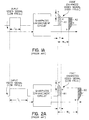
- sharpness enhancement involves accentuation at the edges or contours of the displayed image as shown in Figure 1A.
- the edges are enhanced by increasing the image level at the edge and reducing the image level abruptly.
- EA1 an effectively enhanced area
- the edges are enhanced by decreasing the image level at the edge and increasing the image level abruptly.
- the degree of abruptness is a function of three factors: (1) the difference L between the amplitude of the first and the second signal values (corresponding, for example, to the increased and decreased image levels), (2) the time interval T for the change from the first to the second signal values (or vice versa), and (3) the width of the signal (which, in Figure 1A, is represented by T H ).
- the amplitude difference L as well as the time interval of enhancement T are both fixed. Accordingly, the enhanced area B1 or B2 corresponding to an input signal of a lower frequency (such as that shown in Figure 2A), is substantially identical to the enhanced area A1 or A2 corresponding to an input signal of a higher frequency (such as that shown in Figure 1A). However, since the interval (or width) T W of the input signal is an inverse function of frequency, the effective area EB1 or EB2 of the displayed image (corresponding to the input frequency with the lower frequency) is reduced (see Figure 2B).
- the present invention relates to a multi-frequency display system and method for providing sharpness enhancement.
- the system comprises a sharpness enhancement circuit that is configured to receive a first and a second input video signal, where the first input video signal operates at a first frequency, and the second input video signal operates at a second frequency.
- the system further comprises a controller circuit coupled to the sharpness enhancement circuit, that is configured to generate a first sharpness enhancement signal corresponding to the first frequency and a second sharpness enhancement signal corresponding to the second frequency.
- the sharpness enhancement circuit generates a first control signal in response to the first input video signal and the first enhancement signal, and the sharpness enhancement circuit generates a second control signal based on the second input video signal and the second enhancement signal.
- An electron gun coupled to the sharpness enhancement circuit is configured to provide an first image having a predetermined sharpness level at the first frequency based on the first control signal.
- the electron gun also provides a second image having the predetermined sharpness level at the second frequency based on the second control signal.
- Figure 1A illustrates an input signal with a high frequency and the corresponding enhanced output signal as provided by display systems of the prior art.
- Figure 1B illustrates the displayed image corresponding to the enhanced output signal of Figure 1A.
- Figure 2A illustrates an input signal with a low frequency and the corresponding enhanced output signal as provided by display systems of the prior art.
- Figure 2B illustrates the displayed image corresponding to the enhanced output signal of Figure 2A.
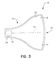
- Figure 3 is a cross sectional view of a conventional cathode ray tube.
- Figure 4 illustrates one embodiment of the multi-frequency sharpness enhancement display system which implements the principles of the present invention.
- Figure 5 illustrates one embodiment of a graph of enhanced levels versus input frequencies, used in implementing the principles of the present invention.
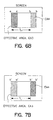
- Figure 6A illustrates an input signal with a high frequency and the corresponding enhanced output signal as provided by the display system provided in accordance with the principles of the present invention.
- Figure 6B illustrates the displayed image corresponding to the enhanced output signal of Figure 6A.
- Figure 7A illustrates an input signal with a low frequency and the corresponding enhanced output signal as provided by the display system provided in accordance with the principles of the present invention.
- Figure 7B illustrates the displayed image corresponding to the enhanced output signal of Figure 7A.
- the present invention is an apparatus and method for providing adaptive sharpness enhancement for multi-frequency systems such as a multi-frequency scan monitor.
- the CRT 10 consists of an electron gun 12 and a phosphor screen 14 that is located inside an evacuated glass envelope 16.
- the narrow neck 18 of the CRT 10 contains the electron gun 12, which generates a beam of electrons 15.
- the beam is accelerated towards the screen 14 by a positive anode voltage.
- the anode 20 is a conductive coating on the inside surface of the wide glass bell portion of the CRT 10.
- the inside of the faceplate 22 is coated with a luminescent material that produces light when excited by electrons in the beam 15.
- a monochrome picture tube has one electron gun and a continuous phosphor coating that produces a picture in black and white.
- the screen 14 is formed with dot trios or vertical lines of red, green and blue phosphors. In such color picture tubes, there are three electron beams, one for each color phosphor. Each of the three electron beams is emitted by a separate cathode.
- FIG 4 illustrates an electronic system 100 that provides calibration of the multi-frequency sharpness enhancement display system 120 in accordance with the principles of the present invention.
- the electronic system 100 comprises a processing system 110 and a multi-frequency sharpness enhancement display system 120 and an adjustment and inspection circuit 160.
- the display system 120 comprises a video controller circuit 130 that includes a timer 132, a processor 134, a memory 138 and a digital-to-analog converter (DAC) 136, a sharpness enhancement circuit 140 and a CRT 150 that includes a red electron gun 152a, a green electron gun 152b and a blue electron gun 152c.
- the processing system 110 is a computer. However, it is contemplated that the processing system 110 may be any processor-based system.
- the CRT 150 is substantially similar to the CRT 10 ( Figure 3).
- the processing system 110 is coupled to the video controller circuit 130 via signal line 116.
- the signal line 116 provides clocking signals from the video processing circuit 114 to the timer 132.
- the signal line 116 provides horizontal synchronization signals HSYNC from the video processing circuit 114 to the timer 132.
- the timer 132 provides timing signals for the processor 134, DAC 136 and memory 138, as well as other circuits in the video controller circuit 130.
- the processing system 110 is also coupled to the sharpness enhancement circuit 140 via signal line 118 and provides input video signals such red, green, and blue input signal information to the sharpness enhancement circuit 140 via signal line 118.
- the controller circuit 130 is also coupled to the sharpness enhancement circuit 140, and provides a sharpness enhancement signal having sharpness enhancement information to the sharpness enhancement circuit 140. Based on the input signals and the sharpness enhancement signal, the sharpness enhancement circuit 140 generates a control signal which is provided to each electron gun 152a, 152b and 152c, so that enhancement of input video signal may be facilitated.
- the sharpness enhancement circuit 140 is that marketed by Sony Corp. under the part designation CXA2093S/M.
- the controller circuit 130 is the controller as marketed by SGS-Thomson under the part designation ST7275.
- the processor system comprises a processor 112 and a video processing circuit 114.
- the processor 112 generates input video signals that are provided to the sharpness enhancement circuit 140 via the video processing circuit 114.
- the processor 112 also generates clocking signals that are provided to the timer 132 in the controller circuit 130.
- the processor 112 is a PentiumTM or a Pentium ProTM processor.
- the timer 132 subsequently generates timing signals for driving the circuitry within the controller circuit 130.
- the processor 134 within the controller circuit 130 generates a control signal that is subsequently converted by the DAC 136 to provide enhancement control for the input video signals provided via signal line 118.
- the control signals include values for operating each electron gun 152a, 152b, and/or 152c at predetermined enhancement levels, as described in detail in the following sections.
- the user operates the calibration system 100 at a first predetermined frequency by configuring the processing system 110 to generate input video signals at a first predetermined frequency.
- the sharpness of the image generated on the screen of the CRT 150 is determined. This can be achieved by an objective method employing an automatic image analysis or a subjective method in which a well-trained user visually inspects the image sharpness.
- the enhancement level is recorded by the adjustment and inspection circuit 160, which subsequently provides values corresponding to the detected frequency and enhancement level to the processor 134 in the controller circuit 130.
- the video controller circuit 130 stores the detected sharpness enhancement value and the corresponding input frequency in memory 138.
- a second set of data points i.e., a sharpness enhancement value for input signals at a second input frequency
- the processor 134 may interpolate the two sets of data (E1, F1) and (E2, F2) to obtain a range of sharpness enhancement levels and the corresponding range of input signal frequencies, so that the resulting displayed image will have substantially identical sharpness enhancement for any input signal provided within the range of input signal frequencies described above.
- Figure 5 illustrates one embodiment of such a plot.
- E1 is 0 with a corresponding input frequency F1 of 30 KHz
- E2 is 153 with a corresponding input frequency F2 of 85 KHz.
- the process for detecting the outputs of the electron guns 152a, 152b and 152c may be performed using the Adjustment/Inspection Standard TS-6999-919M-10.
- Figure 6A illustrates an input signal with a low frequency and the corresponding enhanced output signal as provided by the display system 120 provided in accordance with the principles of the present invention.
- Figure 6B illustrates the displayed image corresponding to the enhanced output signal of Figure 6A.
- Figure 7A illustrates an input signal with a low frequency and the corresponding enhanced output signal as provided by the display system provided in accordance with the principles of the present invention.
- Figure 7B illustrates the displayed image corresponding to the enhanced output signal of Figure 7A.
- the edges are enhanced by the sharpness enhancement circuit 140 by increasing the image level at the edge and reducing the image level abruptly.
- the edges are enhanced by decreasing the image level at the edge and increasing the image level abruptly.
- EA4 as shown in Figure 6B
- the amount of abruptness as indicated by the area B above the line b-b (as shown in Figure 6A).
- the amount of abruptness as indicated by the area A3 or A4 under the line a-a or above the line b-b respectively, as shown in Figure 6A, corresponds to the degree of sharpness.
- the respective effectively enhanced area EA3 or EA4, corresponding to the amount of abruptness, is shown in Figure 6B.
- an enhanced signal having a sharpness level for a particular frequency has an amplitude difference L and a time interval of enhancement T (which is inversely proportional to the frequency of the input signal).
- the present invention adjusts the sharpness enhancement signal provided from the controller circuit 130 to the sharpness enhancement circuit 140 in accordance with the previously stored data (such as the plot shown in Figure 5). As a result, the sharpness of the resulting image is substantially identical to that of an input signal at another frequency.
- an enhanced signal having an amplitude difference L and a time interval of enhancement T' (which is inversely proportional to the frequency of the input signal and larger than T) is provided as shown in Figure 7A.
- the enhanced area B3 or B4 corresponding to an input signal of a lower frequency (see Figure 7A)
- the enhanced area A3 or A4 corresponding to an input signal of a higher frequency (see Figure 6A).
- the effective enhanced area EA3 or EA4 of the displayed image is substantially identical in both cases (see Figures 6B and 7B).
- the outputs of the electron guns 152a, 152b or 152c may be configured to provide display images with sharpness enhancement that is substantially identical for any input signal frequency. As a result, consistently and well enhanced images may be displayed.
- the present invention thus provides a method and apparatus for providing adaptive sharpness enhancement for multi-frequency systems such as a multi-frequency scan monitor.
Landscapes
- Engineering & Computer Science (AREA)
- Theoretical Computer Science (AREA)
- Physics & Mathematics (AREA)
- General Physics & Mathematics (AREA)
- Computer Hardware Design (AREA)
- Remote Sensing (AREA)
- Radar, Positioning & Navigation (AREA)
- Signal Processing (AREA)
- Multimedia (AREA)
- Human Computer Interaction (AREA)
- General Engineering & Computer Science (AREA)
- Picture Signal Circuits (AREA)
- Controls And Circuits For Display Device (AREA)
Applications Claiming Priority (2)
| Application Number | Priority Date | Filing Date | Title |
|---|---|---|---|
| US957881 | 1997-10-27 | ||
| US08/957,881 US6034742A (en) | 1997-10-27 | 1997-10-27 | Adaptive sharpness enhancement for a multi-frequency scanning monitor |
Publications (2)
| Publication Number | Publication Date |
|---|---|
| EP0912044A2 true EP0912044A2 (fr) | 1999-04-28 |
| EP0912044A3 EP0912044A3 (fr) | 2002-02-13 |
Family
ID=25500293
Family Applications (1)
| Application Number | Title | Priority Date | Filing Date |
|---|---|---|---|
| EP98308781A Withdrawn EP0912044A3 (fr) | 1997-10-27 | 1998-10-27 | Amélioration adaptive de la netteté pour un moniteur à balayage multifréquentiel |
Country Status (4)
| Country | Link |
|---|---|
| US (1) | US6034742A (fr) |
| EP (1) | EP0912044A3 (fr) |
| JP (1) | JPH11288237A (fr) |
| KR (1) | KR100529265B1 (fr) |
Families Citing this family (6)
| Publication number | Priority date | Publication date | Assignee | Title |
|---|---|---|---|---|
| US6330040B1 (en) * | 1998-01-29 | 2001-12-11 | Sony Corporation | Apparatus and method for calibrating video displays |
| JP3675357B2 (ja) * | 2001-05-16 | 2005-07-27 | ソニー株式会社 | レジストレーション調整装置及びレジストレーション調整方法 |
| JP3843769B2 (ja) * | 2001-06-25 | 2006-11-08 | 株式会社日立製作所 | 投射型テレビジョン画像表示装置 |
| US6873657B2 (en) * | 2001-12-27 | 2005-03-29 | Koninklijke Philips Electronics, N.V. | Method of and system for improving temporal consistency in sharpness enhancement for a video signal |
| US6862372B2 (en) * | 2001-12-27 | 2005-03-01 | Koninklijke Philips Electronics N.V. | System for and method of sharpness enhancement using coding information and local spatial features |
| JP2004159067A (ja) * | 2002-11-06 | 2004-06-03 | Sanyo Electric Co Ltd | 垂直シャープネス装置及びそれを備えたtv受像機 |
Family Cites Families (4)
| Publication number | Priority date | Publication date | Assignee | Title |
|---|---|---|---|---|
| JPH0496414A (ja) * | 1990-08-10 | 1992-03-27 | Toshiba Corp | 輪郭強調回路 |
| KR920008630B1 (ko) * | 1990-09-28 | 1992-10-02 | 삼성전자 주식회사 | 수평윤곽 보상회로 |
| US5374995A (en) * | 1993-03-22 | 1994-12-20 | Eastman Kodak Company | Method and apparatus for enhancing sharpness of a sequence of images subject to continuous zoom |
| US5587745A (en) * | 1994-07-05 | 1996-12-24 | Thomson Consumer Electronics, Inc. | Adjustment of scan velocity modulation concurrent with the amount of transition rise time, pre-shoot, and overshoot of a video signal |
-
1997
- 1997-10-27 US US08/957,881 patent/US6034742A/en not_active Expired - Fee Related
-
1998
- 1998-10-27 KR KR1019980044984A patent/KR100529265B1/ko not_active Expired - Fee Related
- 1998-10-27 EP EP98308781A patent/EP0912044A3/fr not_active Withdrawn
- 1998-10-27 JP JP10305182A patent/JPH11288237A/ja active Pending
Also Published As
| Publication number | Publication date |
|---|---|
| KR100529265B1 (ko) | 2006-02-28 |
| KR19990037408A (ko) | 1999-05-25 |
| US6034742A (en) | 2000-03-07 |
| JPH11288237A (ja) | 1999-10-19 |
| EP0912044A3 (fr) | 2002-02-13 |
Similar Documents
| Publication | Publication Date | Title |
|---|---|---|
| US3980819A (en) | Edge enhancement for television images | |
| US6369851B1 (en) | Method and apparatus to minimize burn lines on a display | |
| US6034742A (en) | Adaptive sharpness enhancement for a multi-frequency scanning monitor | |
| US6323915B1 (en) | Method and apparatus to enhance a border area of a display | |
| US5886750A (en) | Television receiver including shading correction without deteriorating S/N ratio | |
| US6304034B1 (en) | Cathode ray tube and image correcting method | |
| US6011593A (en) | Cathode ray tube with apparatus for reducing variation of deflection size due to brightness changes | |
| US5841247A (en) | Cathode ray tube, display system incorporating same and computer including control means for display system | |
| JPH07118780B2 (ja) | 画質補償装置 | |
| WO1999014949A1 (fr) | Systeme de detection et de commande de courant de faisceau pour tube cathodique | |
| US6377317B1 (en) | Method and apparatus for correcting color component focusing in a rear-projection television set | |
| US6448945B1 (en) | Vertical pin distortion correction apparatus and method for a multi-scan display | |
| JP2001236899A (ja) | モアレが改善された陰極線管 | |
| EP0912067A2 (fr) | Mise à l'échelle des signaux de sortie d'une cathode | |
| JPH10513331A (ja) | 陰極線管を有する像表示装置 | |
| JPH06269015A (ja) | 画像補正装置 | |
| US6091454A (en) | Method and apparatus for displaying images having adjacent horizontal blocks with sharp contrast on a display unit of a television system | |
| US6570625B1 (en) | Display apparatus and display method | |
| JPH06261219A (ja) | ディスプレイモニタ | |
| US6605898B2 (en) | CRT device with improved resolution | |
| EP1370080B1 (fr) | Appareil et méthode pour afficher des images sur un tube à rayons cathodiques | |
| JP3458507B2 (ja) | 画像表示回路 | |
| JPH07201292A (ja) | Crtディスプレイの鮮鋭度改善回路 | |
| KR20010029786A (ko) | 소직경의 빔 스포트를 공급할 수 있는 씨알티 시스템 | |
| JPH10210385A (ja) | ディスプレイ |
Legal Events
| Date | Code | Title | Description |
|---|---|---|---|
| PUAI | Public reference made under article 153(3) epc to a published international application that has entered the european phase |
Free format text: ORIGINAL CODE: 0009012 |
|
| AK | Designated contracting states |
Kind code of ref document: A2 Designated state(s): AT BE CH CY DE DK ES FI FR GB GR IE IT LI LU MC NL PT SE |
|
| AX | Request for extension of the european patent |
Free format text: AL;LT;LV;MK;RO;SI |
|
| PUAL | Search report despatched |
Free format text: ORIGINAL CODE: 0009013 |
|
| AK | Designated contracting states |
Kind code of ref document: A3 Designated state(s): AT BE CH CY DE DK ES FI FR GB GR IE IT LI LU MC NL PT SE |
|
| AX | Request for extension of the european patent |
Free format text: AL;LT;LV;MK;RO;SI |
|
| AKX | Designation fees paid | ||
| REG | Reference to a national code |
Ref country code: DE Ref legal event code: 8566 |
|
| STAA | Information on the status of an ep patent application or granted ep patent |
Free format text: STATUS: THE APPLICATION IS DEEMED TO BE WITHDRAWN |
|
| 18D | Application deemed to be withdrawn |
Effective date: 20020814 |